2011 NISSAN TIIDA RON 91
[x] Cancel search: RON 91Page 3327 of 3787
PREPARATIONMTC-11
< SERVICE INFORMATION >
C
DE
F
G H
I
K L
M A
B
MTC
N
O P
PREPARATION
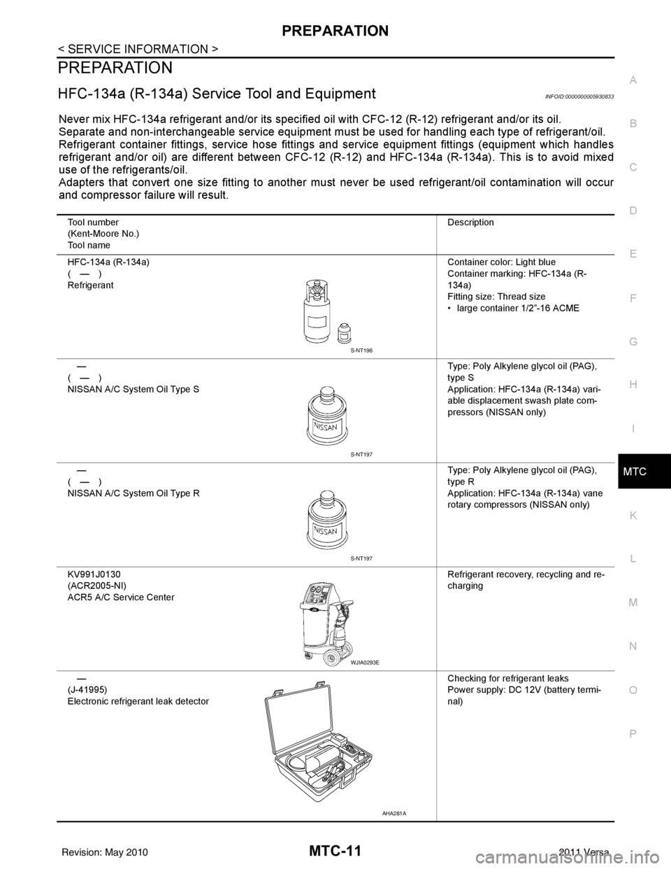
HFC-134a (R-134a) Service Tool and EquipmentINFOID:0000000005930833
Never mix HFC-134a refrigerant and/or its specified oil with CFC-12 (R-12) refrigerant and/or its oil.
Separate and non-interchangeable service equipment must be used for handling each type of refrigerant/oil.
Refrigerant container fittings, service hose fittings and service equipment fittings (equipment which handles
refrigerant and/or oil) are different between CFC-12 (R-12) and HFC-134a (R-134a). This is to avoid mixed
use of the refrigerants/oil.
Adapters that convert one size fitting to another must never be used refrigerant/oil contamination will occur
and compressor failure will result.
Tool number
(Kent-Moore No.)
Tool name Description
HFC-134a (R-134a)
(—)
Refrigerant Container color: Light blue
Container marking: HFC-134a (R-
134a)
Fitting size: Thread size
• large container 1/2”-16 ACME
—
(—)
NISSAN A/C System Oil Type S Type: Poly Alkylene glycol oil (PAG),
type S
Application: HFC-134a (R-134a) vari-
able displacement swash plate com-
pressors (NISSAN only)
—
(—)
NISSAN A/C System Oil Type R Type: Poly Alkylene glycol oil (PAG),
type R
Application: HFC-134a (R-134a) vane
rotary compressors (NISSAN only)
KV991J0130
(ACR2005-NI)
ACR5 A/C Se rvice Center Refrigerant recovery, recycling and re-
charging
—
(J-41995)
Electronic refrigerant leak detector Checking for refrigerant leaks
Power supply: DC 12V (battery termi-
nal)
S-NT196
S-NT197
S-NT197
WJIA0293E
AHA281A
Revision: May 2010
2011 Versa
Page 3329 of 3787
PREPARATIONMTC-13
< SERVICE INFORMATION >
C
DE
F
G H
I
K L
M A
B
MTC
N
O P
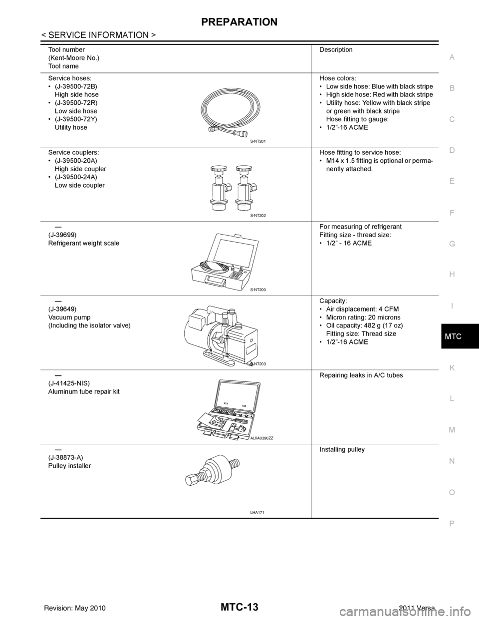
Service hoses:
• (J-39500-72B) High side hose
• (J-39500-72R) Low side hose
• (J-39500-72Y)
Utility hose Hose colors:
• Low side hose: Blue with black stripe
• High side hose: Red with black stripe
• Utility hose: Yellow with black stripe
or green with black stripe
Hose fitting to gauge:
• 1/2”-16 ACME
Service couplers:
• (J-39500-20A) High side coupler
• (J-39500-24A)
Low side coupler Hose fitting to service hose:
• M14 x 1.5 fitting is optional or perma-
nently attached.
—
(J-39699)
Refrigerant weight scale For measuring of refrigerant
Fitting size - thread size:
• 1/2” - 16 ACME
—
(J-39649)
Va c u u m p u m p
(Including the isolator valve) Capacity:
• Air displacement: 4 CFM
• Micron rating: 20 microns
• Oil capacity: 482 g (17 oz)
Fitting size: Thread size
• 1/2”-16 ACME
—
(J-41425-NIS)
Aluminum tube repair kit Repairing leaks in A/C tubes
—
(J-38873-A)
Pulley installer Installing pulley
Tool number
(Kent-Moore No.)
Tool name
Description
S-NT201
S-NT202
S-NT200
S-NT203
ALIIA0390ZZ
LHA171
Revision: May 2010
2011 Versa
Page 3341 of 3787
TROUBLE DIAGNOSISMTC-25
< SERVICE INFORMATION >
C
DE
F
G H
I
K L
M A
B
MTC
N
O P
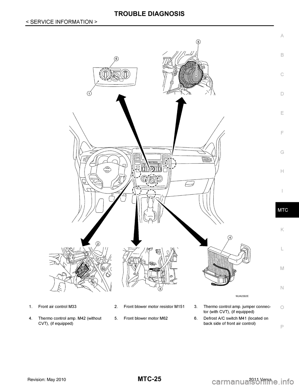
1. Front air control M33 2. Front blower motor resistor M151 3. Thermo control amp. jumper connec-
tor (with CVT), (if equipped)
4. Thermo control amp. M42 (without CVT), (if equipped) 5. Front blower motor M62
6. Defrost A/C switch M41 (located on
back side of front air control)
WJIA2302E
Revision: May 2010 2011 Versa
Page 3348 of 3787
MTC-32
< SERVICE INFORMATION >
TROUBLE DIAGNOSIS
1. Turn blower control dial clockwise to "1" position. Blower should operate on low speed.
2. Turn blower control dial clockwise to "2" position, and continue checking blower speed until all speeds are
checked.
3. Leave blower on Maximum speed.
If NG, go to trouble diagnosis procedure for MTC-34, "
Front Blower Motor Circuit".
If OK, continue the check.
CHECKING DISCHARGE AIR
1. Turn mode door control dial to each position.
2. Confirm that discharge air comes out according to the air distribution table. Refer to MTC-20, "
Discharge
Air Flow".
If NG, go to trouble diagnosis procedure for MTC-32, "
Mode Door".
If OK, continue the check.
CHECKING RECIRCULATION
1. Set intake door lever to REC position.
2. Operate intake door lever to FRE position.
3. Listen for intake door position change (you should hear blower sound change slightly).
If NG, go to trouble diagnosis procedure for MTC-34, "
Intake Door".
If OK, continue the check.
CHECKING TEMPERATURE DECREASE
1. Turn temperature control dial counterclockwise to full cold position.
2. Check for cold air at discharge air outlets.
If NG, go to trouble diagnosis procedure for MTC-46, "
Insufficient Cooling".
If OK, continue the check.
CHECKING TEMPERATURE INCREASE
1. Turn temperature control dial clockwise to full hot position.
2. Check for hot air at discharge air outlets.
If NG, go to trouble diagnosis procedure for MTC-53, "
Insufficient Heating".
If OK, continue the check.
CHECKING A/C SWITCH (IF EQUIPPED)
1. Turn fan control dial to the desired (1 to 4 speed) position.
2. Press A/C switch.
3. A/C switch indicator will turn ON.
• Confirm that the compressor clutch engages (sound or visual inspection).
If NG, go to trouble diagnosis procedure for MTC-38, "
Magnet Clutch Circuit (If Equipped)".
If OK, continue the check.
CHECKING DEFROST A/C SWITCH (IF EQUIPPED)
1. Turn fan control dial to the desired (1 to 4 speed) position.
2. Turn mode dial to ( ) DEF.
3. Confirm that the compressor clutch engages (sound or visual inspection) and the A/C switch indicator illu- minates.
If NG, go to trouble diagnosis procedure for MTC-38, "
Magnet Clutch Circuit (If Equipped)".
If all operational checks are OK (symptom cannot be duplicated), go to MTC-23, "
How to Perform Trouble
Diagnosis for Quick and Accurate Repair" and perform tests as outlined. If symptom appears, refer to MTC-23,
"How to Perform Trouble Diagnosis for Quick and Accurate Repair" and perform applicable trouble diagnosis
procedures.
Mode DoorINFOID:0000000005930849
SYMPTOM: Air outlet does not change.
INSPECTION FLOW
Revision: May 2010 2011 Versa
Page 3350 of 3787
MTC-34
< SERVICE INFORMATION >
TROUBLE DIAGNOSIS
>> GO TO 5.
5.CHECK AIR MIX DOOR CONTROL LINKAGE
Check and verify air mix door mechanism for smooth operation.
OK or NG
OK >> If the symptom still exists, perform a complete operational check. Refer to MTC-31, "Operational
Check" If other symptoms exist, refer to MTC-23, "How to Perform Trouble Diagnosis for Quick
and Accurate Repair".
NG >> Repair or adjust air mix door control linkage. Refer to MTC-65, "
Air Mix Door Cable Adjustment".
Intake DoorINFOID:0000000005930851
SYMPTOM:
• Intake door does not change.
INSPECTION FLOW
1.CONFIRM SYMPTOM BY PERFORMING OPERATIONAL CHECK - REC ( )
1. Slide the intake door lever to the REC ( ) position.
2. Turn the blower motor to maximum speed.
3. Slide the intake door lever to the FRE position.
4. Listen for intake door position change (you should hear blower sound change slightly).
Can a symptom be duplicated?
YES >> GO TO 3.
NO >> GO TO 2.
2.PERFORM COMPLETE OPERATIONAL CHECK
Perform a complete operational check and check for any symptoms. Refer to MTC-31, "
Operational Check" .
Can a symptom be duplicated?
YES >> Refer to MTC-23, "How to Perform Trouble Diagnosis for Quick and Accurate Repair" .
NO >> System OK.
3.CHECK FOR SERVICE BULLETINS
Check for any service bulletins.
>> GO TO 4.
4.CHECK INTAKE DOOR CONTROL LINKAGE
Check intake door control linkage mechanism for smooth operation.
OK or NG
OK >> If the symptom still exists, perform a complete operational check. Refer to MTC-31, "Operational
Check" . If other symptoms exist, refer to MTC-23, "How to Perform Trouble Diagnosis for Quick
and Accurate Repair" .
NG >> Repair or adjust control linkage. Refer to MTC-64, "
Intake Door Cable Adjustment" .
Front Blower Motor CircuitINFOID:0000000005930852
SYMPTOM: Front blower motor operation is malfunctioning.
INSPECTION FLOW
1.CONFIRM SYMPTOM BY PERFORMING OPERATIONAL CHECK - FRONT BLOWER
1. Turn blower control dial to "1" position. Blower should operate on low speed.
2. Turn the blower control dial to "2" position, and continue checking blower speed until all speeds are
checked.
Can the symptom be duplicated?
YES >> GO TO 3.
Revision: May 2010 2011 Versa
Page 3351 of 3787
TROUBLE DIAGNOSISMTC-35
< SERVICE INFORMATION >
C
DE
F
G H
I
K L
M A
B
MTC
N
O P
NO >> GO TO 2.
2.PERFORM COMPLETE OPERATIONAL CHECK
Perform a complete operational check and check for any symptoms. Refer to MTC-31, "
Operational Check".
Can a symptom be duplicated?
YES >> Refer to MTC-23, "How to Perform Trouble Diagnosis for Quick and Accurate Repair".
NO >> System OK.
3.CHECK FOR SERVICE BULLETINS
Check for any service bulletins.
>> GO TO 4.
4.CHECK FRONT BLOWER MOTOR CIRCUIT
Check front blower motor circuit. Refer to "D IAGNOSTIC PROCEDURE FOR FRONT BLOWER MOTOR" .
OK or NG
OK >> If the symptom still exists, perform a complete operational check. Refer to MTC-31, "Operational
Check". If other symptoms exist, refer to MTC-23, "How to Perform Trouble Diagnosis for Quick
and Accurate Repair".
NG >> Repair as necessary.
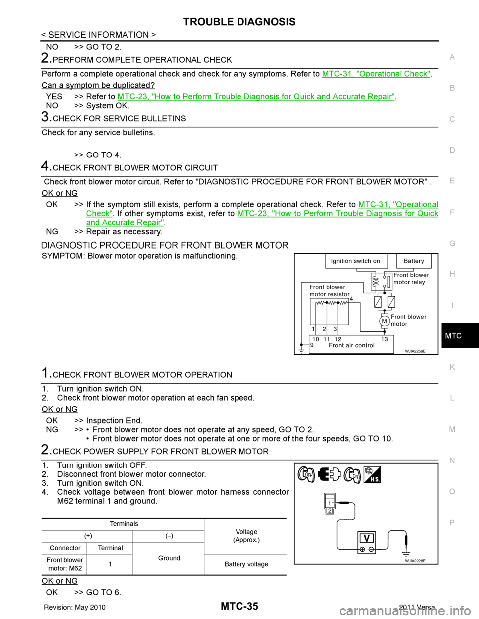
DIAGNOSTIC PROCEDURE FOR FRONT BLOWER MOTOR
SYMPTOM: Blower motor operation is malfunctioning.
1.CHECK FRONT BLOWER MOTOR OPERATION
1. Turn ignition switch ON.
2. Check front blower motor operation at each fan speed.
OK or NG
OK >> Inspection End.
NG >> • Front blower motor does not operate at any speed, GO TO 2. • Front blower motor does not operate at one or more of the four speeds, GO TO 10.
2.CHECK POWER SUPPLY FOR FRONT BLOWER MOTOR
1. Turn ignition switch OFF.
2. Disconnect front blower motor connector.
3. Turn ignition switch ON.
4. Check voltage between front blower motor harness connector M62 terminal 1 and ground.
OK or NG
OK >> GO TO 6.
WJIA2259E
Te r m i n a l s Vol tag e
(Approx.)
(+)
(− )
Connector Terminal Ground
Front blower
motor: M62 1
Battery voltage
WJIA2228E
Revision: May 2010 2011 Versa
Page 3352 of 3787
![NISSAN TIIDA 2011 Service Repair Manual MTC-36
< SERVICE INFORMATION >
TROUBLE DIAGNOSIS
NG >> Check power supply circuit and 15A fuses [Nos. 15 and 17, located in the fuse block (J/B)].Refer to PG-4, "
Schematic".
• If fuses are OK, rein NISSAN TIIDA 2011 Service Repair Manual MTC-36
< SERVICE INFORMATION >
TROUBLE DIAGNOSIS
NG >> Check power supply circuit and 15A fuses [Nos. 15 and 17, located in the fuse block (J/B)].Refer to PG-4, "
Schematic".
• If fuses are OK, rein](/manual-img/5/57396/w960_57396-3351.png)
MTC-36
< SERVICE INFORMATION >
TROUBLE DIAGNOSIS
NG >> Check power supply circuit and 15A fuses [Nos. 15 and 17, located in the fuse block (J/B)].Refer to PG-4, "
Schematic".
• If fuses are OK, reinstall fuses and GO TO 3.
• If fuses are NG, replace fuse and check harness for short circuit. Repair or replace if necessary.
3.CHECK BLOWER MOTOR RELAY POWER SUPPLY CIRCUITS
1. Turn ignition switch OFF.
2. Disconnect blower motor relay connector.
3. Turn ignition switch ON.
4. Check voltage between blower motor relay harness connector J- 1 terminal 1, 5 and ground.
OK or NG
OK >> GO TO 4.
NG >> Repair harness or connector.
4.CHECK BLOWER MOTOR RELAY (S WITCH SIDE) CIRCUIT FOR OPEN
1. Turn ignition switch OFF.
2. Check continuity between blower motor relay harness connector J-1 (A) terminal 3 and front blower motor harness connector
M62 (B) terminal 1.
OK or NG
OK >> GO TO 5.
NG >> Repair harness or connector.
5.CHECK BLOWER MOTOR RELAY GROUND CIRCUIT
Check continuity between blower motor relay harness connector J-1
terminal 2 and ground.
OK or NG
OK >> Replace blower motor relay.
NG >> Repair harness or connector.
6.CHECK FRONT BLOWER MOTOR
Check continuity between front blower motor terminals 1 and 2.
NOTE:
Ensure that there are no foreign particles inside the A/C unit assem-
bly for a smooth rotation of the front blower motor.
OK or NG
OK >> GO TO 7.
NG >> Replace front blower motor. Refer to MTC-63, "
Removal
and Installation".
7.CHECK CIRCUIT CONTINUITY BETWEEN FRONT BLOWER MOTOR AND FRONT AIR CONTROL
1 - Ground Battery voltage should exist.
5 - Ground Battery voltage should exist.
WJIA1783E
Continuity should exist.
WJIA2263E
Continuity should exist.
WJIA2264E
1 - 2
: Continuity should exist.
WJIA2230E
Revision: May 2010 2011 Versa
Page 3353 of 3787
TROUBLE DIAGNOSISMTC-37
< SERVICE INFORMATION >
C
DE
F
G H
I
K L
M A
B
MTC
N
O P
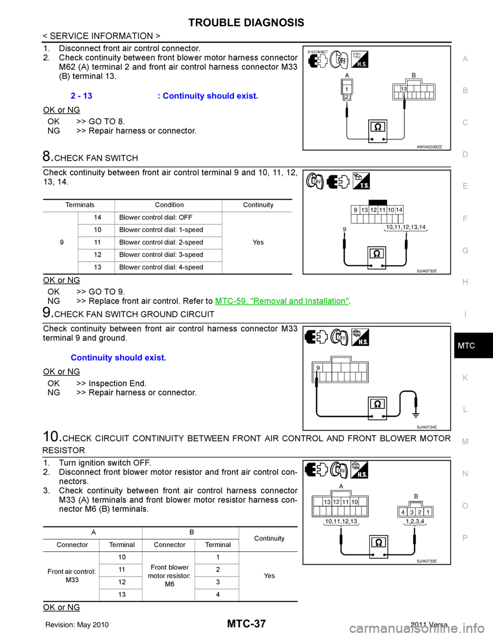
1. Disconnect front air control connector.
2. Check continuity between front blower motor harness connector M62 (A) terminal 2 and front air control harness connector M33
(B) terminal 13.
OK or NG
OK >> GO TO 8.
NG >> Repair harness or connector.
8.CHECK FAN SWITCH
Check continuity between front ai r control terminal 9 and 10, 11, 12,
13, 14.
OK or NG
OK >> GO TO 9.
NG >> Replace front air control. Refer to MTC-59, "
Removal and Installation".
9.CHECK FAN SWITCH GROUND CIRCUIT
Check continuity between front air control harness connector M33
terminal 9 and ground.
OK or NG
OK >> Inspection End.
NG >> Repair harness or connector.
10.CHECK CIRCUIT CONTINUITY BETWEEN FRONT AIR CONTROL AND FRONT BLOWER MOTOR
RESISTOR
1. Turn ignition switch OFF.
2. Disconnect front blower motor resistor and front air control con- nectors.
3. Check continuity between front air control harness connector
M33 (A) terminals and front blower motor resistor harness con-
nector M6 (B) terminals.
OK or NG
2 - 13 : Continuity should exist.
AWIIA0339ZZ
Terminals ConditionContinuity
9 14 Blower control dial: OFF
Ye s
10 Blower control dial: 1-speed
11 Blower control dial: 2-speed
12 Blower control dial: 3-speed
13 Blower control dial: 4-speed
SJIA0732E
Continuity should exist.
SJIA0734E
AB Continuity
Connector Terminal Connector Terminal
Front air control: M33 10
Front blower
motor resistor: M6 1
Ye s
11
2
12 3
13 4
SJIA0733E
Revision: May 2010 2011 Versa