2011 NISSAN TIIDA clutch system
[x] Cancel search: clutch systemPage 3355 of 3787
TROUBLE DIAGNOSISMTC-39
< SERVICE INFORMATION >
C
DE
F
G H
I
K L
M A
B
MTC
N
O P
6.CHECK MAGNET CLUTCH CIRCUIT
Perform diagnostic procedure for the magnetic clutch . Refer to "DIAGNOSTIC PROCEDURE FOR MAGNET
CLUTCH".
OK or NG
OK >> If the symptom still exists, perform a complete operational check. Refer to MTC-31, "Operational
Check". If other symptoms exist, refer to MTC-23, "How to Perform Trouble Diagnosis for Quick
and Accurate Repair".
NG >> Repair as necessary.
SYSTEM DESCRIPTION
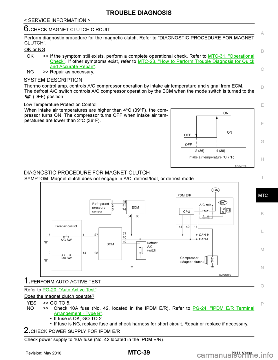
Thermo control amp. controls A/C compressor operation by intake air temperature and signal from ECM.
The defrost A/C switch controls A/C compressor operati on by the BCM when the mode switch is turned to the
(DEF) position.
Low Temperature Protection Control
When intake air temperatures are higher than 4 °C (39° F), the com-
pressor turns ON. The compressor turns OFF when intake air tem-
peratures are lower than 2 °C (36° F).
DIAGNOSTIC PROCEDURE FOR MAGNET CLUTCH
SYMPTOM: Magnet clutch does not engage in A/C, defrost/foot, or defrost mode.
1.PERFORM AUTO ACTIVE TEST
Refer to PG-20, "
Auto Active Test".
Does the magnet clutch operate?
YES >> GO TO 5.
NO >> Check 10A fuse (No. 42, located in the IPDM E/R). Refer to PG-24, "
IPDM E/R Terminal
Arrangement - Type B".
• If fuse is OK, GO TO 2.
• If fuse is NG, replace fuse and check harness for short circuit. Repair or replace if necessary.
2.CHECK POWER SUPPLY FOR IPDM E/R
Check power supply to 10A fuse (No. 42 located in the IPDM E/R).
SJIA0741E
WJIA2250E
Revision: May 2010 2011 Versa
Page 3368 of 3787
MTC-52
< SERVICE INFORMATION >
TROUBLE DIAGNOSIS
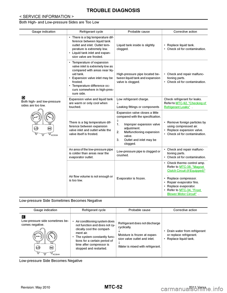
Both High- and Low-pressure Sides are Too Low
Low-pressure Side Sometimes Becomes Negative
Low-pressure Side Becomes Negative
Gauge indication Refrigerant cycle Probable causeCorrective action
Both high- and low-pressure
sides are too low. • There is a big temperature dif-
ference between liquid tank
outlet and inlet. Outlet tem-
perature is extremely low.
• Liquid tank inlet and expan- sion valve are frosted. Liquid tank inside is slightly
clogged.
• Replace liquid tank.
• Check oil for contamination.
• Temperature of expansion valve inlet is extremely low as
compared with areas near liq-
uid tank.
• Expansion valve inlet may be
frosted.
• Temperature difference oc- curs somewhere in high-pres-
sure side. High-pressure pipe located be-
tween liquid tank and expansion
valve is clogged.
• Check and repair malfunc-
tioning parts.
• Check oil for contamination.
Expansion valve and liquid tank
are warm or only cool when
touched. Low refrigerant charge.
↓
Leaking fittings or componentsCheck refrigerant for leaks.
Refer to
MTC-92, "
Checking of
Refrigerant Leaks" .
There is a big temperature dif-
ference between expansion
valve inlet and outlet while the
valve itself is frosted. Expansion valve closes a little
compared with the specification.
↓
1. Improper expansion valve
adjustment.
2. Malfunctioning expansion valve.
3. Outlet and inlet may be clogged. • Remove foreign particles by
using compressed air.
• Replace expansion valve.
• Check oil for contamination.
An area of the low-pressure pipe
is colder than areas near the
evaporator outlet. Low-pressure pipe is clogged or
crushed.• Check and repair malfunc-
tioning parts.
• Check oil for contamination.
Air flow volume is not enough or
is too low. Evaporator is frozen.• Check thermo control amp.
Refer to MTC-38, "
Magnet
Clutch Circuit (If Equipped)"
.
• Replace compressor.
• Repair evaporator fins.
• Replace evaporator.
•Refer to MTC-34, "
Front
Blower Motor Circuit" .
AC353A
Gauge indication Refrigerant cycleProbable causeCorrective action
Low-pressure side sometimes be-
comes negative. • Air conditioning system does
not function and does not cy-
clically cool the compart-
ment air.
• The system constantly func-
tions for a certain period of
time after compressor is
stopped and restarted. Refrigerant does not discharge
cyclically.
↓
Moisture is frozen at expan-
sion valve outlet and inlet.
↓
Water is mixed with refrigerant.
• Drain water from refrigerant
or replace refrigerant.
• Replace liquid tank.
AC354A
Revision: May 2010 2011 Versa
Page 3437 of 3787

IPDM E/R (INTELLIGENT POWER DISTRIBUTION MODULE ENGINE ROOM)
PG-17
< SERVICE INFORMATION >
C
D E
F
G H
I
J
L
M A
B
PG
N
O P
IPDM E/R (INTELLIGENT POWER DISTRIBUTION MODULE ENGINE
ROOM)
System DescriptionINFOID:0000000005928343
• IPDM E/R (Intelligent Power Distribution Module Engi ne Room) integrates the relay box and fuse block
which were originally placed in engine compartment. It controls integrated relays via IPDM E/R control cir-
cuits.
• IPDM E/R-integrated control circuits perform ON-OFF operation of relays, CAN communication control, oil pressure switch signal reception, etc.
• It controls operation of each electrical co mponent via ECM, BCM and CAN communication lines.
CAUTION:
None of the IPDM E/R integr ated relays can be removed.
SYSTEMS CONTROLLED BY IPDM E/R
1. Lamp control
Using CAN communication lines, it receives signals from the BCM and controls the following lamps:
• Headlamps (High, Low)
• Parking lamps
• Tail and license plate lamps
• Front fog lamps
2. Wiper control Using CAN communication lines, it receives signals from the BCM and controls the front wipers.
3. Rear window defogger relay control Using CAN communication lines, it receives signals from the BCM and controls the rear window defogger
relay.
4. A/C compressor control Using CAN communication lines, it receives signal s from the ECM and controls the A/C compressor
(magnet clutch).
5. Starter control Using CAN communication lines, it receives signals from the BCM and controls the starter relay.
6. Cooling fan control Using CAN communication lines, it receives signals from the ECM and controls the cooling fan relays.
7. Horn control Using CAN communication lines, it receives signals from the BCM and controls the horn relay.
8. Daytime light system control (Canada only) Using CAN communication lines, it receives signals from the BCM and controls the daytime light relay.
CAN COMMUNICATION LINE CONTROL
With CAN communication, by connecting each control unit using two communication lines (CAN L-line, CAN
H-line), it is possible to transmit a maximum amount of information with minimum wiring. Each control unit can
transmit and receive data, and reads necessary information only.
1. Fail-safe control • When CAN communication with other control units is impossible, IPDM E/R performs fail-safe control.
After CAN communication returns to normal operation, it also returns to normal control.
• Operation of control parts by IPDM E/ R during fail-safe mode is as follows:
Controlled system Fail-safe mode
Headlamp • With the ignition switch ON, headlamp low relay is ON, headlamp high relays are OFF, and
daytime light system (Canada only) is OFF.
• With the ignition switch OFF, the headlamp relays are OFF.
Tail, license plate and parking lamps • With the ignition switch ON, the tail lamp relay is ON. • With the ignition switch OFF, the tail lamp relay is OFF.
Cooling fan • With the ignition switch ON, cooling fan relay-1, relay-2, and relay-3 are ON.
• With the ignition switch OFF, all cooling fan relays are OFF.
Front wiper Until the ignition switch is turned off, the front wiper relays remain in the same status they
were in just before fail
−safe control was initiated.
Revision: May 2010 2011 Versa
Page 3440 of 3787

PG-20
< SERVICE INFORMATION >
IPDM E/R (INTELLIGENT POWER DISTRIBUTION MODULE ENGINE ROOM)
*1 Perform monitoring of IPDM E/R data with the ignition switch ON. When the ignition switch is in ACC position, display may no t be cor-
rect.
*2 This item is displayed, but does not function.
CAN DIAG SUPPORT MNTR
Refer to LAN-9, "Description" .
ACTIVE TEST
Display Item List
Auto Active TestINFOID:0000000005928347
DESCRIPTION
• In auto active test mode, operation inspection can be performed when IPDM E/R sends a drive signal to the
following systems:
- Rear window defogger
- Front wipers
- Tail, license and parking lamps
- Daytime lamp system (Canada only)
- Front fog lamps
- Headlamps (High, Low)
- A/C compressor (magnet clutch)
- Cooling fan
OPERATION PROCEDURE
1. Close hood and front door RH, and lift wiper arms away from windshield (to prevent glass damage by wiper operation).
NOTE:
When auto active test is performed with hood opened, sprinkle water on windshield beforehand.
2. Turn ignition switch OFF.
3. Turn ignition switch ON and, within 20 seconds, pres s front door switch LH 10 times. Then turn ignition
switch OFF.
4. Turn ignition switch ON within 10 seconds after ignition switch OFF.
5. When auto active test mode is actuated, horn chirps once.
6. After a series of operations is repeated three times, auto active test is completed.
Theft warning
horn request THFT HRN REQ ON/OFF
XX Signal status input from BCM
Horn chirp HORN CHIRP ON/OFF XX Output status of IPDM E/R
Daytime light re-
quest DTRL REQ ON/OFF
XX Signal status input from BCM
Item name
CONSULT-III
screen display Display or unit Monitor item selection
Description
ALL
SIGNALS MAIN
SIGNALS SELECTION
FROM MENU
Test name CONSULT-III screen display Description
Head, tail, fog lamp output EXTERNAL LAMPS With a certain ON-OFF operation (OFF, TAIL, LO, HI, FOG), the front
fog lamp, headlamp low, headlamp high RH, headlamp high LH, and
tail lamp relays can be operated.
Rear defogger output REAR DEFOGGER With a certain ON-OFF operation, the rear defogger relay can be oper-
ated.
Front wiper (HI, LO) output FRONT WIPER With a certain operation (OFF, HI ON, LO ON), the front wiper relays
(Lo, Hi) can be operated.
Cooling fan output MOTOR FAN With a certain operation (1, 2, 3, 4), the cooling fan relays can be oper-
ated.
Horn output HORN With a certain ON-OFF operation, the horn relay can be operated.
Revision: May 2010 2011 Versa
Page 3441 of 3787
IPDM E/R (INTELLIGENT POWER DISTRIBUTION MODULE ENGINE ROOM)
PG-21
< SERVICE INFORMATION >
C
D E
F
G H
I
J
L
M A
B
PG
N
O P
NOTE:
When auto active test mode has to be cancelled halfway, turn ignition switch OFF.
CAUTION:
Be sure to perform BL-44, "
Door Switch Check (Hatchback)" or BL-47, "Door Switch Check
(Sedan)" when the auto active test cannot be performed.
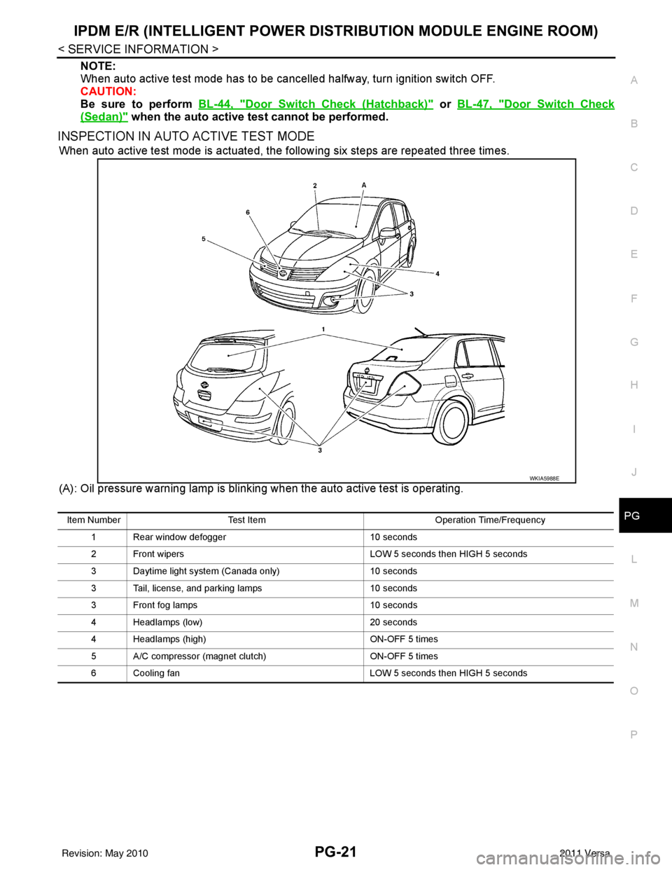
INSPECTION IN AUTO ACTIVE TEST MODE
When auto active test mode is actuated, the following six steps are repeated three times.
(A): Oil pressure warning lamp is blinking when the auto active test is operating.
WKIA5988E
Item Number Test Item Operation Time/Frequency
1 Rear window defogger 10 seconds
2 Front wipers LOW 5 seconds then HIGH 5 seconds
3 Daytime light system (Canada only) 10 seconds
3 Tail, license, and parking lamps 10 seconds
3 Front fog lamps 10 seconds
4 Headlamps (low) 20 seconds
4 Headlamps (high) ON-OFF 5 times
5 A/C compressor (magnet clutch) ON-OFF 5 times
6 Cooling fan LOW 5 seconds then HIGH 5 seconds
Revision: May 2010 2011 Versa
Page 3442 of 3787
PG-22
< SERVICE INFORMATION >
IPDM E/R (INTELLIGENT POWER DISTRIBUTION MODULE ENGINE ROOM)
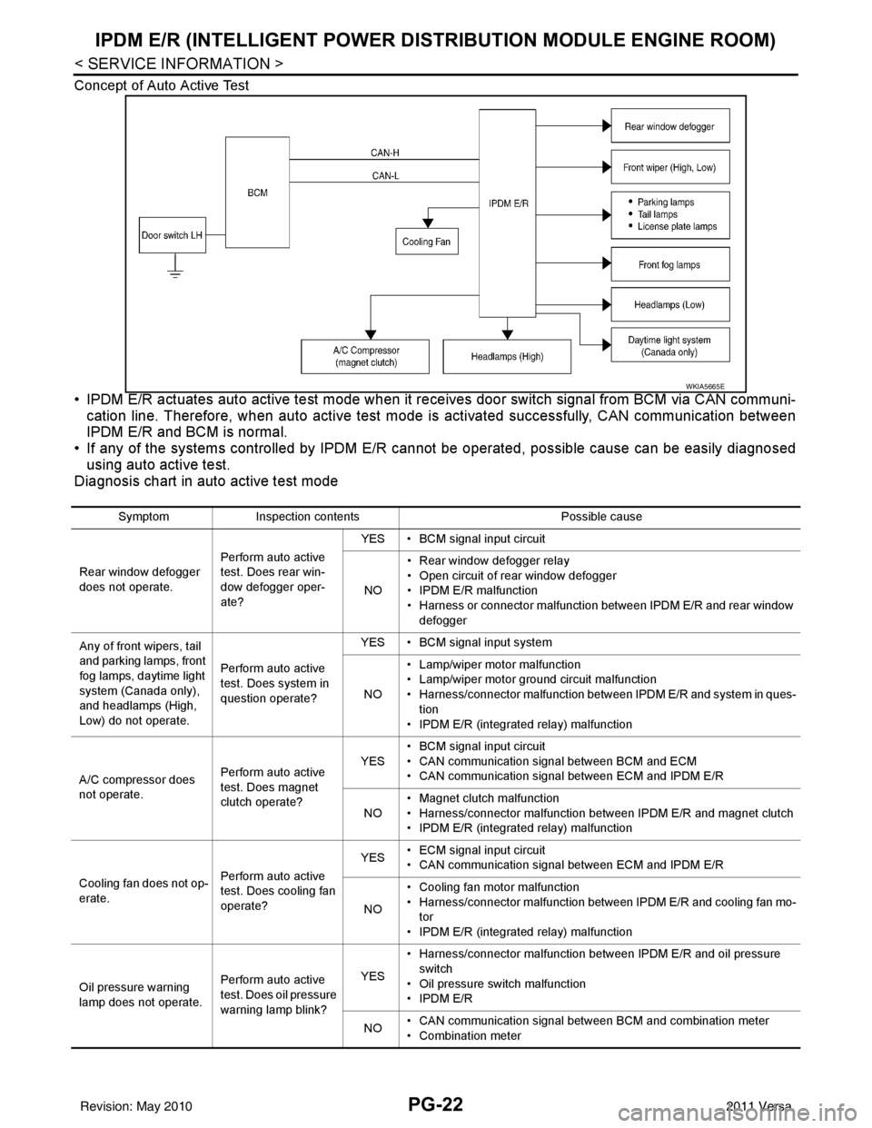
Concept of Auto Active Test
• IPDM E/R actuates auto active test mode when it re ceives door switch signal from BCM via CAN communi-
cation line. Therefore, when auto active test mode is activated successfully, CAN communication between
IPDM E/R and BCM is normal.
• If any of the systems controll ed by IPDM E/R cannot be operated, possible cause can be easily diagnosed
using auto active test.
Diagnosis chart in auto active test mode
WKIA5665E
Symptom Inspection contents Possible cause
Rear window defogger
does not operate. Perform auto active
test. Does rear win-
dow defogger oper-
ate?YES • BCM signal input circuit
NO • Rear window defogger relay
• Open circuit of rear window defogger
•IPDM E/R malfunction
• Harness or connector malfunction between IPDM E/R and rear window
defogger
Any of front wipers, tail
and parking lamps, front
fog lamps, daytime light
system (Canada only),
and headlamps (High,
Low) do not operate. Perform auto active
test. Does system in
question operate?YES • BCM signal input system
NO • Lamp/wiper motor malfunction
• Lamp/wiper motor ground circuit malfunction
• Harness/connector malfunction between IPDM E/R and system in ques-
tion
• IPDM E/R (integrated relay) malfunction
A/C compressor does
not operate. Perform auto active
test. Does magnet
clutch operate?YES
• BCM signal input circuit
• CAN communication signal between BCM and ECM
• CAN communication signal between ECM and IPDM E/R
NO • Magnet clutch malfunction
• Harness/connector malfunction between IPDM E/R and magnet clutch
• IPDM E/R (integrated relay) malfunction
Cooling fan does not op-
erate. Perform auto active
test. Does cooling fan
operate?YES
• ECM signal input circuit
• CAN communication signal between ECM and IPDM E/R
NO • Cooling fan motor malfunction
• Harness/connector malfunction between IPDM E/R and cooling fan mo-
tor
• IPDM E/R (integrated relay) malfunction
Oil pressure warning
lamp does not operate. Perform auto active
test. Does oil pressure
warning lamp blink?YES
• Harness/connector malfunction between IPDM E/R and oil pressure
switch
• Oil pressure switch malfunction
•IPDM E/R
NO • CAN communication signal between BCM and combination meter
• Combination meter
Revision: May 2010
2011 Versa
Page 3446 of 3787

PG-26
< SERVICE INFORMATION >
IPDM E/R (INTELLIGENT POWER DISTRIBUTION MODULE ENGINE ROOM)
24 Y Cooling fan relay-3 Output — Conditions correct for cooling
fan high operation
Battery voltage
Conditions not correct for
cooling fan high operation 0V
26 O Tail lamp relay (park-
ing lamps) Output — Lighting switch in 2nd position Battery voltage
27 BR Tail lamp relay (park-
ing lamps)
Output — Lighting switch in 2nd position Battery voltage
28 GR Tail lamp relay (park-
ing lamps) Output — Lighting switch in 2nd position Battery voltage
29 P Tail lamp relay (park-
ing lamps) Output — Lighting switch in 2nd position Battery voltage
30
(A/T
only) R Fuse 54
Output —Ignition switch ON or START
Battery voltage
Ignition switch OFF or ACC 0V
31 O Fuse 55 Output —Ignition switch ON or START
Battery voltage
Ignition switch OFF or ACC 0V
32 L Wiper high speed sig-
nal
OutputON or
START Wiper switch OFF, LO, INT
0V
HI Battery voltage
33 Y Wiper low speed sig-
nal
OutputON or
START Wiper switch OFF
0V
LO or INT Battery voltage
35 BR Starter relay (inhibit
switch) InputON or
START Selector lever in "P" or "N"
(CVT or A/T) or clutch pedal
depressed (M/T)
Battery voltage
Selector lever any other posi-
tion (CVT or A/T) or clutch
pedal released (M/T) 0V
36 BR Fuel pump relay Output — Ignition switch ON or START
Battery voltage
Ignition switch OFF or ACC 0V
37 G Oil pressure switch Input ON or
START Engine running and oil pres-
sure within specification
Battery voltage
Engine not running or oil pres-
sure below specification 0V
38 R Wiper auto stop signal Input ON or
START Wipers not in park position
Battery voltage
Wipers in park position 0V
39 B Ground Input ——0V
40 P CAN-L — ON— —
41 L CAN-H — ON— —
45 R Horn relay control Input — Horn switch PUSHED, alarm
switch activated or door lock/
unlock is confirmed when op-
erating lock system via the
keyfob
0V
Horn switch released, alarm
not active, keyfob not active Battery voltage
46 Y Throttle control motor
relay control Input —Ignition switch ON or START
0V
Ignition switch OFF or ACC Battery voltage
47 GR Fuel pump relay con-
trol Input —Ignition switch ON or START
0V
Ig niti
on switch OFF or ACC Battery voltage
Te r m i n a l
Wire
color Signal name Signal
input/
output Measuring condition
Reference value
(Approx.)
Ignition
switch Operation or condition
Revision: May 2010
2011 Versa
Page 3479 of 3787

HARNESSPG-59
< SERVICE INFORMATION >
C
DE
F
G H
I
J
L
M A
B
PG
N
O P
H/LAMP LT Headlamp
H/PHON AV Hands Free Telephone
HORN WW Horn
HO2S2 EC Heated Oxygen Sensor 2
HO2S2H EC Heated Oxygen Sensor 2 Heater
IATS EC Intake Air Temperature Sensor
IGNSYS EC Ignition System
I/KEY BL Intelligent Key System
ILL LT Illumination
INJECT EC Injector
INT/L LT Room/Map, Vanity and Luggage Lamps
IVC EC Intake Valve Timing Control Solenoid Valve
KEYLES BL Remote Keyless Entry System
KS EC Knock Sensor
LPSV AT Line Pressure Solenoid Valve
LPSV CVT Line Pressure Solenoid Valve
L/USSV CVT Lock-up Select Solenoid Valve
MAFS EC Mass Air Flow Sensor
MAIN AT Main Power Supply and Ground Circuit
MAIN EC Main Power Supply and Ground Circuit
METER DI Speedometer, Tachometer, Temp. and Fuel Gauges
MIL/DL EC Malfunction Indicator Lamp
MIRROR GW Door Mirror
NATS BL Nissan Anti-Theft System
NONDTC AT Non-detectable Item
NONDTC CVT Non-detectable Item
ODSW CVT Overdrive Control Switch
OVRCSV AT Over Run Clutch Solenoid Valve
P/SCKT WW Power Socket
PGC/V EC EVAP Canister Purge Vo lume Control Solenoid Valve
PHASE EC Camshaft Position Sensor (PHASE)
PNP/SW EC Park/Neutral Position Switch
POS EC Crankshaft Position Sensor (POS)
POWER CVT Transmission Control Module (Power Supply)
PRE/SE EC EVAP Control System Pressure Sensor
PRIPS CVT Primary Pressure Sensor
PRSCVT CVT Primary Speed Sensor CVT (Input Speed Sensor)
PT/SEN AT Powertrain Revolution Sensor
RP/SEN EC Refrigerant Pressure Sensor
SECPS CVT Secondary Pressure Sensor
SECPSV CVT Secondary Speed Sensor CVT (Input Speed Sensor)
SEN/PW EC Sensor Power Supply
SESCVT CVT Secondary Pressure Sensor Solenoid Valve
SHIFT AT A/T Shift Lock System
SHIFT CVT CVT Shift Lock System
SROOF RF Sunroof
SRS SRS Supplemental Restraint System
SSV/A AT Shift Solenoid Valve A
SSV/B AT Shift Solenoid Valve B
START SC Starting System
STM CVT Step Motor
STOP/L LT Stop Lamp
Revision: May 2010 2011 Versa