2011 NISSAN TIIDA clutch system
[x] Cancel search: clutch systemPage 3283 of 3787
![NISSAN TIIDA 2011 Service Repair Manual MT-62
< SERVICE INFORMATION >[RS6F94R]
TRANSAXLE ASSEMBLY
• When installing the transaxle assembly to the engine, install the
bolts as shown.
CAUTION:
When installing transaxle assembly, be careful](/manual-img/5/57396/w960_57396-3282.png "NISSAN TIIDA 2011 Service Repair Manual MT-62
< SERVICE INFORMATION >[RS6F94R]
TRANSAXLE ASSEMBLY
• When installing the transaxle assembly to the engine, install the
bolts as shown.
CAUTION:
When installing transaxle assembly, be careful")
MT-62
< SERVICE INFORMATION >[RS6F94R]
TRANSAXLE ASSEMBLY
• When installing the transaxle assembly to the engine, install the
bolts as shown.
CAUTION:
When installing transaxle assembly, be careful not to bring
transaxle input shaft into co ntact with clutch cover.
A: M/T to engine
B: Engine to M/T
• Bleed the air from the clutch hydraulic system. Refer to CL-9, "
Air Bleeding Procedure".
• After installation, check oil level, and check for leaks and loose mechanisms. Refer to MT-54, "
Checking M/T
Oil".
Disassembly and AssemblyINFOID:0000000005929698
COMPONENTS
Case and Housing Components
Bolt No.12
Quantity 36
Bolt length “ ” mm (in) 60 (2.36)
50 (1.97)
Tightening torque
N·m (kg-m, ft-lb) 62.0 (6.3, 46)
PCIB1786E
Revision: May 2010
2011 Versa
Page 3317 of 3787

MTC-1
AIR CONDITIONER
C
DE
F
G H
I
K L
M
SECTION MTC
A
B
MTC
N
O P
CONTENTS
MANUAL AIR CONDITIONER
SERVICE INFORMATION .. ..........................3
PRECAUTIONS .............................................. .....3
Precaution for Supplemental Restraint System
(SRS) "AIR BAG" and "SEAT BELT PRE-TEN-
SIONER" ............................................................. ......
3
Precaution Necessary for Steering Wheel Rota-
tion After Battery Disconnect ............................... ......
3
Precaution for Procedure without Cowl Top Cover ......4
Precaution for Working with HFC-134a (R-134a) ......4
General Refrigerant Precaution ................................4
Oil Precaution ............................................................5
Precaution for Refrigerant Connection ......................5
Precaution for Service of Compressor ................ ......8
Precaution for Service Equipment ....................... ......8
Precaution for Leak Detection Dye ...........................9
PREPARATION ..................................................11
HFC-134a (R-134a) Service Tool and Equipment ....11
Commercial Service Tool ........................................14
REFRIGERATION SYSTEM ..............................15
Refrigerant Cycle ................................................ ....15
Refrigerant System Protection ................................15
Component Part Location ................................... ....16
OIL ......................................................................17
Maintenance of Oil Quantity in Compressor ....... ....17
AIR CONDITIONER CONTROL .........................19
Control Operation ................................................ ....19
Discharge Air Flow ..................................................20
System Description .................................................20
TROUBLE DIAGNOSIS .....................................22
CONSULT-III Function (BCM) ............................. ....22
How to Perform Trouble Diagnosis for Quick and
Accurate Repair ......................................................
23
Component Parts and Harness Connector Loca-
tion ...................................................................... ....
23
Schematic ...............................................................26
Wiring Diagram - Heater - .......................................27
Wiring Diagram - A/C,M - .................................... ....28
Operational Check ...................................................31
Mode Door ...............................................................32
Air Mix Door .............................................................33
Intake Door ..............................................................34
Front Blower Motor Circuit .......................................34
Magnet Clutch Circuit (If Equipped) ..................... ....38
Insufficient Cooling ..................................................46
Insufficient Heating ..................................................53
Noise .......................................................................54
CONTROLLER ..................................................56
Removal and Installation .........................................56
Disassembly and Assembly .....................................57
THERMO CONTROL AMPLIFIER ....................58
Removal and Installation .........................................58
A/C UNIT ASSEMBLY ......................................59
Removal and Installation .........................................59
Disassembly and Assembly .....................................61
BLOWER MOTOR ............................................63
Removal and Installation .........................................63
INTAKE DOOR ..................................................64
Intake Door Cable Adjustment .................................64
AIR MIX DOOR .................................................65
Air Mix Door Cable Adjustment ...............................65
MODE DOOR ....................................................66
Mode Door Cable Adjustment .................................66
BLOWER FAN RESISTOR ...............................67
Removal and Installation .........................................67
HEATER CORE .................................................68
Removal and Installation .........................................68
DUCTS AND GRILLES .....................................69
Removal and Installation .........................................69
Revision: May 2010 2011 Versa
Page 3318 of 3787

MTC-2
REFRIGERANT LINES ......................................74
HFC-134a (R-134a) Service Procedure .............. ...74
Component .............................................................76
Removal and Installation of Compressor -
HR16DE .................................................................
78
Removal and Installation of Compressor -
MR18DE .................................................................
80
Removal and Installation for Compressor Clutch -
Type 1 .................................................................. ...
81
Removal and Installation for Compressor Clutch -
Type 2 .................................................................. ...
83
Removal and Installation of Low-Pressure Flexi-
ble Hose .................................................................
86
Removal and Installation of High-Pressure Flexi-
ble Hose .................................................................
87
Removal and Installation of High-Pressure Pipe ....88
Removal and Installation of Refrigerant Pressure
Sensor .................................................................. ...
89
Removal and Installation of Condenser ..................89
Removal and Installation of Liquid Tank .................90
Removal and Installation of Evaporator ............... ...91
Removal and Installation of Expansion Valve .........92
Checking of Refrigerant Leaks ................................92
Checking System for Leaks Using the Fluorescent
Leak Detector ..........................................................
92
Dye Injection ...........................................................93
Electronic Refrigerant Leak Detector ......................93
SERVICE DATA AND SPECIFICATIONS
(SDS) .................................................................
96
Compressor ......................................................... ...96
Oil ............................................................................96
Refrigerant ..............................................................96
Revision: May 2010 2011 Versa
Page 3324 of 3787
MTC-8
< SERVICE INFORMATION >
PRECAUTIONS
Precaution for Service of Compressor
INFOID:0000000005930830
• Plug all openings to prevent moisture and foreign matter from entering.
• When the compressor is removed, store it in th e same position as it is when mounted on the car.
• When replacing or repairing compressor, follow “Maintenance of Oil Quantity in Compressor”
exactly. Refer to MTC-17, "
Maintenance of Oil Quantity in Compressor".
• Keep friction surfaces between clut ch and pulley clean. If the surface is contaminated, with oil, wipe
it off by using a clean waste cloth moistened with thinner.
• After compressor service operation, turn the compresso r shaft by hand more than five turns in both
directions. This will equally distribute oil inside the compressor. After the compressor is installed,
let the engine idle and operate the compressor for one hour.
• After replacing the compressor magnet clutch, ap ply voltage to the new one and check for usual
operation.
Precaution for Service EquipmentINFOID:0000000005930831
RECOVERY/RECYCLING EQUIPMENT
Be certain to follow the manufacturer’s instructions for machine operation and machine maintenance. Never
introduce any refrigerant other than that specified into the machine.
ELECTRONIC LEAK DETECTOR
Be certain to follow the manufacturer’s instruct ions for tester operation and tester maintenance.
VACUUM PUMP
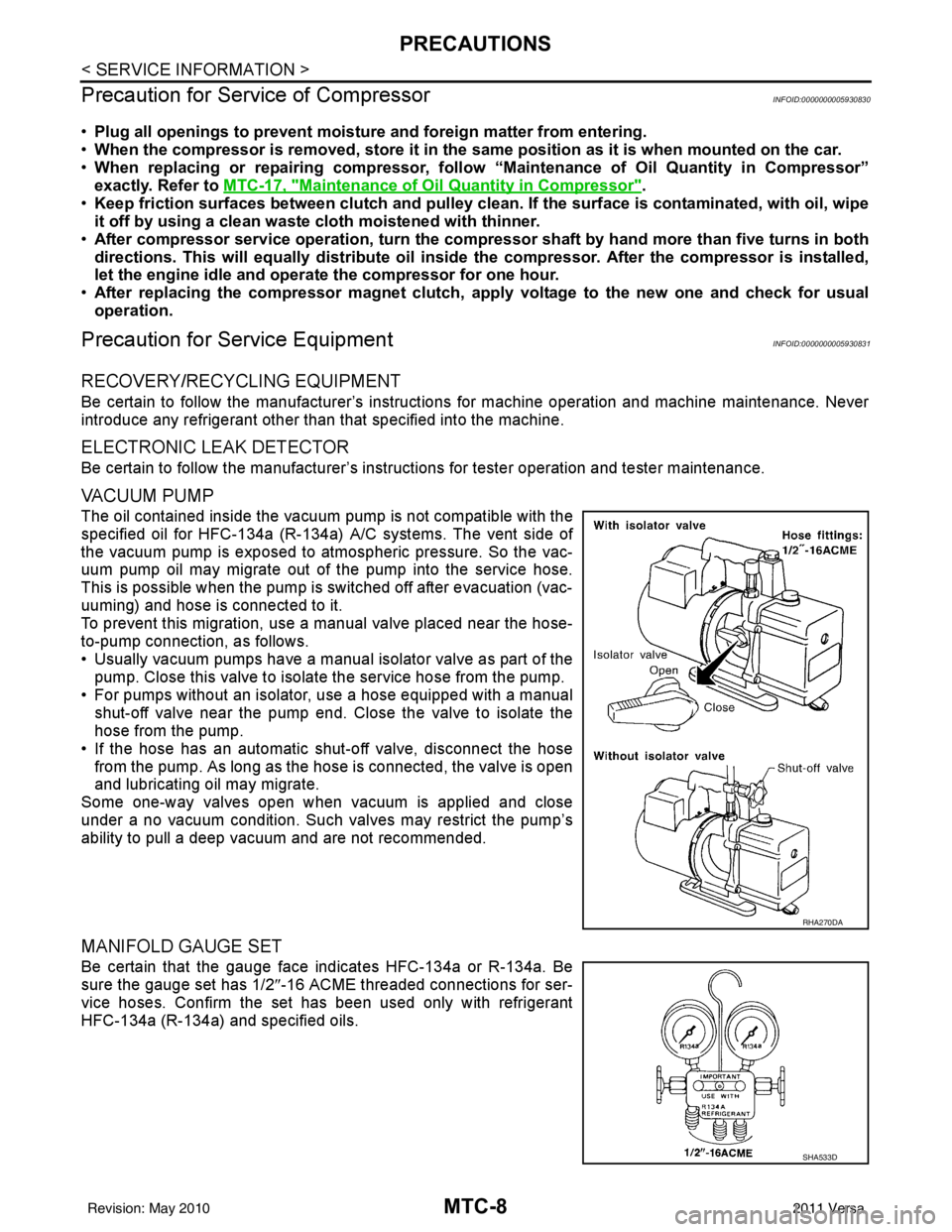
The oil contained inside the vacuum pump is not compatible with the
specified oil for HFC-134a (R-134a) A/C systems. The vent side of
the vacuum pump is exposed to atmospheric pressure. So the vac-
uum pump oil may migrate out of the pump into the service hose.
This is possible when the pump is switched off after evacuation (vac-
uuming) and hose is connected to it.
To prevent this migration, use a manual valve placed near the hose-
to-pump connection, as follows.
• Usually vacuum pumps have a manual isolator valve as part of the pump. Close this valve to isolat e the service hose from the pump.
• For pumps without an isolator, use a hose equipped with a manual shut-off valve near the pump end. Close the valve to isolate the
hose from the pump.
• If the hose has an automatic shut -off valve, disconnect the hose
from the pump. As long as the hose is connected, the valve is open
and lubricating oil may migrate.
Some one-way valves open when vacuum is applied and close
under a no vacuum condition. Such valves may restrict the pump’s
ability to pull a deep vacuum and are not recommended.
MANIFOLD GAUGE SET
Be certain that the gauge face indicates HFC-134a or R-134a. Be
sure the gauge set has 1/2 ″-16 ACME threaded connections for ser-
vice hoses. Confirm the set has been used only with refrigerant
HFC-134a (R-134a) and specified oils.
RHA270DA
SHA533D
Revision: May 2010 2011 Versa
Page 3330 of 3787
MTC-14
< SERVICE INFORMATION >
PREPARATION
Commercial Service Tool
INFOID:0000000005930834
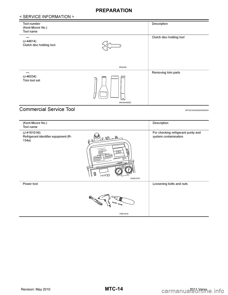
—
(J-44614)
Clutch disc holding tool Clutch disc holding tool
—
(J-46534)
Trim tool set Removing trim parts
Tool number
(Kent-Moore No.)
Tool name
Description
WHA230
AWJIA0483ZZ
(Kent-Moore No.)
Tool name
Description
(J-41810-NI)
Refrigerant identifier equipment (R-
134a) For checking refrigerant purity and
system contamination
Power tool Loosening bolts and nuts
RJIA0197E
PIIB1407E
Revision: May 2010 2011 Versa
Page 3339 of 3787
TROUBLE DIAGNOSISMTC-23
< SERVICE INFORMATION >
C
DE
F
G H
I
K L
M A
B
MTC
N
O P
WORK SUPPORT
Display Item List
How to Perform Trouble Diagnosis for Quick and Accurate RepairINFOID:0000000005930843
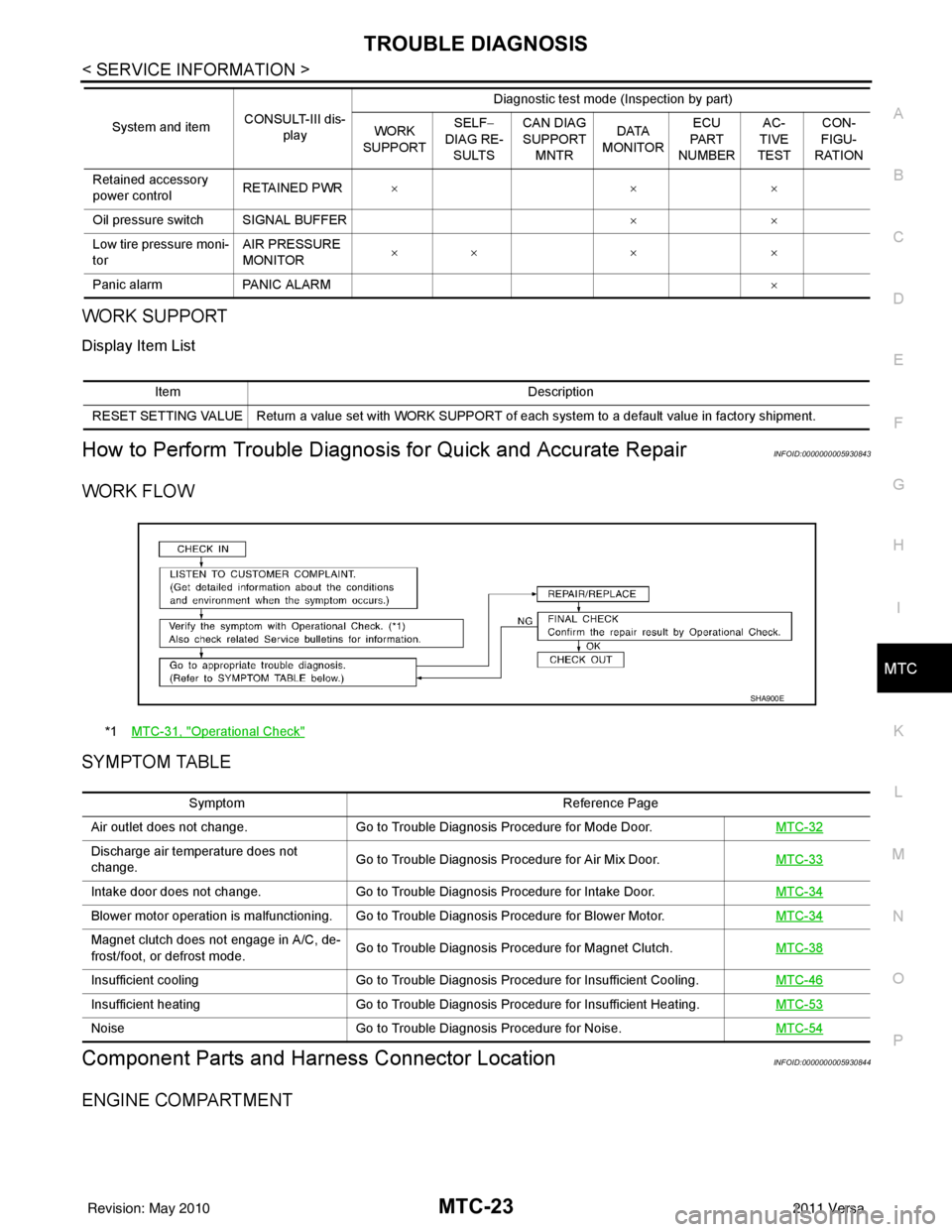
WORK FLOW
SYMPTOM TABLE
Component Parts and Har ness Connector LocationINFOID:0000000005930844
ENGINE COMPARTMENT
Retained accessory
power controlRETAINED PWR
×× ×
Oil pressure switch SIGNAL BUFFER ××
Low tire pressure moni-
tor AIR PRESSURE
MONITOR
××
× ×
Panic alarm PANIC ALARM ×
System and item
CONSULT-III dis-
play Diagnostic test mode (Inspection by part)
WORK
SUPPORT SELF
−
DIAG RE-
SULTS CAN DIAG
SUPPORT
MNTR DATA
MONITOR ECU
PA R T
NUMBER AC-
TIVE
TEST CON-
FIGU-
RATION
Item Description
RESET SETTING VALUE Return a value set with WORK SUPPORT of each system to a default value in factory shipment.
*1 MTC-31, "Operational Check"
SHA900E
Symptom Reference Page
Air outlet does not change. Go to Trouble Diagnosis Procedure for Mode Door. MTC-32
Discharge air temperature does not
change.Go to Trouble Diagnosis Procedure for Air Mix Door.
MTC-33
Intake door does not change.Go to Trouble Diagnosis Procedure for Intake Door. MTC-34
Blower motor operation is malfunctioning. Go to Trouble Diagnosis Procedure for Blower Motor. MTC-34
Magnet clutch does not engage in A/C, de-
frost/foot, or defrost mode.Go to Trouble Diagnosis Procedure for Magnet Clutch.
MTC-38
Insufficient coolingGo to Trouble Diagnosis Procedure for Insufficient Cooling. MTC-46
Insufficient heatingGo to Trouble Diagnosis Procedure for Insufficient Heating. MTC-53
NoiseGo to Trouble Diagnosis Procedure for Noise. MTC-54
Revision: May 2010 2011 Versa
Page 3349 of 3787
TROUBLE DIAGNOSISMTC-33
< SERVICE INFORMATION >
C
DE
F
G H
I
K L
M A
B
MTC
N
O P
1.CONFIRM SYMPTOM BY PERFORMING O PERATIONAL CHECK - DISCHARGE AIR
1. Rotate the mode door control dial to each position.
2. Confirm that discharge air comes out accord ing to the air distribution table. Refer to MTC-20, "
Discharge
Air Flow".
NOTE:
Confirm that the compressor clutch (with A/C) is engaged (visual inspection) when DEF ( ) or D/F ( )
is selected.
Can a symptom be duplicated?
YES >> GO TO 3.
NO >> GO TO 2.
2.PERFORM COMPLETE OPERATIONAL CHECK
Perform a complete operational check and check for any symptoms. Refer to MTC-31, "
Operational Check".
Can a symptom be duplicated?
YES >> Refer to MTC-23, "How to Perform Trouble Diagnosis for Quick and Accurate Repair".
NO >> System OK.
3.CHECK FOR SERVICE BULLETINS
Check for any service bulletins.
>> GO TO 4.
4.CHECK MODE DOOR CONTROL CABLE
Check and verify mode door mechanism for smooth operation in each mode.
OK or NG
OK >> If the symptom still exists, perform a comple te operational check and check for other symptoms.
Refer to MTC-31, "
Operational Check". If other symptoms exist, refer to MTC-23, "How to Perform
Trouble Diagnosis for Quick and Accurate Repair" .
NG >> Repair or adjust mode door control cable. Refer to MTC-66, "
Mode Door Cable Adjustment".
Air Mix DoorINFOID:0000000005930850
SYMPTOM: Air mix door does not change.
INSPECTION FLOW
1.CONFIRM SYMPTOM BY PERFORMING OPERATIONAL CHECK - TEMPERATURE INCREASE
1. Turn the temperature control dial clockwise until maximum heat.
2. Check for hot air at discharge air outlets.
>> GO TO 2.
2.CONFIRM SYMPTOM BY PERFORMING OPERAT IONAL CHECK - TEMPERATURE DECREASE
1. Turn the temperature control dial counterclockwise until maximum cold.
2. Check for cold air at discharge air outlets.
Can a symptom be duplicated?
YES >> GO TO 4.
NO >> GO TO 3.
3.PERFORM COMPLETE OPERATIONAL CHECK
Perform a complete operational check and check for any symptoms. Refer to MTC-31, "
Operational Check".
Can a symptom be duplicated?
YES >> Refer to MTC-23, "How to Perform Trouble Diagnosis for Quick and Accurate Repair".
NO >> System OK.
4.CHECK FOR SERVICE BULLETINS
Check for any service bulletins.
Revision: May 2010 2011 Versa
Page 3354 of 3787
MTC-38
< SERVICE INFORMATION >
TROUBLE DIAGNOSIS
OK >> GO TO 11.
NG >> Repair harness or connector.
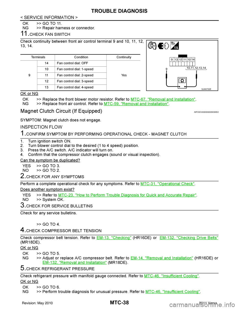
11 .CHECK FAN SWITCH
Check continuity between front air control terminal 9 and 10, 11, 12,
13, 14.
OK or NG
OK >> Replace the front blower motor resistor. Refer to MTC-67, "Removal and Installation".
NG >> Replace front air control. Refer to MTC-59, "
Removal and Installation".
Magnet Clutch Circuit (If Equipped)INFOID:0000000005930853
SYMPTOM: Magnet clutch does not engage.
INSPECTION FLOW
1.CONFIRM SYMPTOM BY PERFORMING OP ERATIONAL CHECK - MAGNET CLUTCH
1. Turn ignition switch ON.
2. Turn blower control dial to the desired (1 to 4 speed) position.
3. Press the A/C switch. A/C indicator will turn on.
4. Confirm that the compressor clut ch engages (sound or visual inspection).
Can the symptom be duplicated?
YES >> GO TO 3.
NO >> GO TO 2.
2.CHECK FOR ANY SYMPTOMS
Perform a complete operational check for any symptoms. Refer to MTC-31, "
Operational Check".
Does another symptom exist?
YES >> Refer to MTC-23, "How to Perform Trouble Diagnosis for Quick and Accurate Repair".
NO >> System OK.
3.CHECK FOR SERVICE BULLETINS
Check for any service bulletins.
>> GO TO 4.
4.CHECK COMPRESSOR BELT TENSION
Check compressor belt tension. Refer to EM-13, "
Checking" (HR16DE) or EM-132, "Checking Drive Belts"
(MR18DE).
OK or NG
OK >> GO TO 5.
NG >> Adjust or replace A/C compressor belt. Refer to EM-14, "
Removal and Installation" (HR16DE) or
EM-132, "
Removal and Installation" (MR18DE).
5.CHECK REFRIGERANT PRESSURE
Check refrigerant pressure with manifold gauge connected. Refer to MTC-46, "
Insufficient Cooling".
OK or NG
OK >> GO TO 6.
NG >> Perform trouble diagnosis for unusual pressure. Refer to MTC-46, "
Insufficient Cooling".
TerminalsConditionContinuity
9 14 Fan control dial: OFF
Ye s
10 Fan control dial: 1-speed
11 Fan control dial: 2-speed
12 Fan control dial: 3-speed
13 Fan control dial: 4-speed
SJIA0732E
Revision: May 2010 2011 Versa