2011 NISSAN LATIO lock
[x] Cancel search: lockPage 2166 of 3787
![NISSAN LATIO 2011 Service Repair Manual EC-872
< SERVICE INFORMATION >[MR18DE]
DTC P0455 EVAP CONTROL SYSTEM
>>
INSPECTION END
Component InspectionINFOID:0000000006342038
DRAIN FILTER
1. Check visually for insect nests in the drain filter a NISSAN LATIO 2011 Service Repair Manual EC-872
< SERVICE INFORMATION >[MR18DE]
DTC P0455 EVAP CONTROL SYSTEM
>>
INSPECTION END
Component InspectionINFOID:0000000006342038
DRAIN FILTER
1. Check visually for insect nests in the drain filter a](/manual-img/5/57357/w960_57357-2165.png)
EC-872
< SERVICE INFORMATION >[MR18DE]
DTC P0455 EVAP CONTROL SYSTEM
>>
INSPECTION END
Component InspectionINFOID:0000000006342038
DRAIN FILTER
1. Check visually for insect nests in the drain filter air inlet.
2. Check visually for cracks or flaws in the appearance.
3. Check visually for cracks or flaws in the hose.
4. Blow air into port A and check t hat it flows freely out of port B.
5. Block port B.
6. Blow air into port A and check that there is no leakage.
7. If NG, replace drain filter.
PBIB3641E
Revision: May 2010 2011 Versa
Page 2169 of 3787
![NISSAN LATIO 2011 Service Repair Manual DTC P0456 EVAP CONTROL SYSTEMEC-875
< SERVICE INFORMATION > [MR18DE]
C
D
E
F
G H
I
J
K L
M A
EC
NP
O
2. Set the pressure pump and a hose.
3. Also set the pressure pump with pressure gauge to the EVAP
NISSAN LATIO 2011 Service Repair Manual DTC P0456 EVAP CONTROL SYSTEMEC-875
< SERVICE INFORMATION > [MR18DE]
C
D
E
F
G H
I
J
K L
M A
EC
NP
O
2. Set the pressure pump and a hose.
3. Also set the pressure pump with pressure gauge to the EVAP](/manual-img/5/57357/w960_57357-2168.png)
DTC P0456 EVAP CONTROL SYSTEMEC-875
< SERVICE INFORMATION > [MR18DE]
C
D
E
F
G H
I
J
K L
M A
EC
NP
O
2. Set the pressure pump and a hose.
3. Also set the pressure pump with pressure gauge to the EVAP
service port adapter.
4. Turn ignition switch ON.
5. Connect GST and select Service $08.
6. Using Service $08 control the EVAP canister vent control valve
(close).
7. Apply pressure and make sure the following conditions are sat- isfied.
Pressure to be applied: 2.7 kPa (20 mmHg, 0.79 inHg)
Time to be waited after the pressure drawn in to the EVAP
system and the pressure to be dropped: 60 seconds and
the pressure should not be dropped more than 0.4 kPa (3 mmHg, 0.12 inHg).
If NG, go to EC-875, "
Diagnosis Procedure".
If OK, go to next step.
8. Disconnect GST.
9. Start engine and warm it up to normal operating temperature.
10. Turn ignition switch OFF and wait at least 10 seconds.
11. Restart engine and let it idle for 90 seconds.
12. Keep engine speed at 2,000 rpm for 30 seconds.
13. Turn ignition switch OFF. NOTE:
For more information, refer to GST Instruction Manual.
Diagnosis ProcedureINFOID:0000000006342042
1.CHECK FUEL FILLER CAP DESIGN
1. Turn ignition switch OFF.
2. Check for genuine NISSAN fuel filler cap design.
OK or NG
OK >> GO TO 2.
NG >> Replace with genuine NISSAN fuel filler cap.
2.CHECK FUEL FILLER CAP INSTALLATION
Check that the cap is tightened properly by rotating the cap clockwise.
OK or NG
OK >> GO TO 3.
NG >> 1. Open fuel filler cap, then clean cap and fuel filler neck threads using air blower. 2. Retighten until reteaching sound is heard.
3.CHECK FUEL FILLER CAP FUNCTION
Check for air releasing sound while opening the fuel filler cap.
OK or NG
OK >> GO TO 5.
NG >> GO TO 4.
4.CHECK FUEL TANK VACUUM RELIEF VALVE
Refer to EC-528, "
Component Inspection".
OK or NG
OK >> GO TO 5.
NG >> Replace fuel filler cap with a genuine one.
SEF462UI
SEF915U
Revision: May 2010 2011 Versa
Page 2174 of 3787
![NISSAN LATIO 2011 Service Repair Manual EC-880
< SERVICE INFORMATION >[MR18DE]
DTC P0456 EVAP CONTROL SYSTEM
NG >> Replace fuel level sensor unit.
25.CHECK INTERMITTENT INCIDENT
Refer to EC-632
.
>> INSPECTION END
Component InspectionINFOI NISSAN LATIO 2011 Service Repair Manual EC-880
< SERVICE INFORMATION >[MR18DE]
DTC P0456 EVAP CONTROL SYSTEM
NG >> Replace fuel level sensor unit.
25.CHECK INTERMITTENT INCIDENT
Refer to EC-632
.
>> INSPECTION END
Component InspectionINFOI](/manual-img/5/57357/w960_57357-2173.png)
EC-880
< SERVICE INFORMATION >[MR18DE]
DTC P0456 EVAP CONTROL SYSTEM
NG >> Replace fuel level sensor unit.
25.CHECK INTERMITTENT INCIDENT
Refer to EC-632
.
>> INSPECTION END
Component InspectionINFOID:0000000006342043
DRAIN FILTER
1. Check visually for insect nests in the drain filter air inlet.
2. Check visually for cracks or flaws in the appearance.
3. Check visually for cracks or flaws in the hose.
4. Blow air into port A and check t hat it flows freely out of port B.
5. Block port B.
6. Blow air into port A and check that there is no leakage.
7. If NG, replace drain filter.
PBIB3641E
Revision: May 2010 2011 Versa
Page 2213 of 3787
![NISSAN LATIO 2011 Service Repair Manual DTC P1217 ENGINE OVER TEMPERATUREEC-919
< SERVICE INFORMATION > [MR18DE]
C
D
E
F
G H
I
J
K L
M A
EC
NP
O
Cooling fan motor terminal 2 and IPDM E/R terminal 24.
Cooling fan motor terminal 3 and IPDM E/ NISSAN LATIO 2011 Service Repair Manual DTC P1217 ENGINE OVER TEMPERATUREEC-919
< SERVICE INFORMATION > [MR18DE]
C
D
E
F
G H
I
J
K L
M A
EC
NP
O
Cooling fan motor terminal 2 and IPDM E/R terminal 24.
Cooling fan motor terminal 3 and IPDM E/](/manual-img/5/57357/w960_57357-2212.png)
DTC P1217 ENGINE OVER TEMPERATUREEC-919
< SERVICE INFORMATION > [MR18DE]
C
D
E
F
G H
I
J
K L
M A
EC
NP
O
Cooling fan motor terminal 2 and IPDM E/R terminal 24.
Cooling fan motor terminal 3 and IPDM E/R terminal 23.
Cooling fan motor terminal 4 and ground.
Refer to wiring diagram.
3. Also check harness for short to ground and short to power.
OK or NG
OK >> GO TO 15.
NG >> GO TO 14.
14.DETECT MALFUNCTIONING PART
Check the following.
• Harness for open or short between cooling fan motor and IPDM E/R
• Harness for open or short between cooling fan motor and ground
>> Repair open circuit or short to ground or short to power in harness or connectors.
15.CHECK COOLING FAN MOTOR
Refer to EC-920, "
Component Inspection".
OK or NG
OK >> GO TO 16.
NG >> Replace cooling fan motor.
16.CHECK INTERMITTENT INCIDENT
Perform EC-632
.
OK or NG
OK >> Replace IPDM E/R. Refer to PG-28, "Removal and Installation of IPDM E/R".
NG >> Repair or replace harness or connector.
Main 13 Causes of OverheatingINFOID:0000000006342106
Continuity should exist.
Engine Step Inspection item EquipmentStandardReference
OFF 1
• Blocked radiator
• Blocked condenser
• Blocked radiator grille
• Blocked bumper • Visual
No blocking —
2 • Coolant mixture • Coolant tester See MA-15, "
Anti-freeze Coolant Mixture Ratio".
3 • Coolant level • VisualCoolant up to MAX level in
reservoir tank and radiator
filler neck See
MA-26, "
ENGINE
COOLANT : Inspection".
4 • Radiator cap • Pressure tester See CO-39, "
Checking Radiator Cap".
ON*
25 • Coolant leaks • VisualNo leaks See CO-36, "Inspection".
ON*
26 • Thermostat • Touch the upper and
lower radiator hoses Both hoses should be hot See CO-47, and
CO-40
ON*17 • Cooling fan • CONSULT-IIIOperating See trouble diagnosis for
DTC P1217 (
EC-916, "Di-
agnosis Procedure").
OFF 8 • Combustion gas leak • Color checker chemical
tester 4 Gas analyzer Negative
—
ON*
39 • Coolant temperature
gauge •Visual
Gauge less than 3/4 when
driving —
• Coolant overflow to res- ervoir tank •Visual No overflow during driving
and idling See
CO-36
.
Revision: May 2010 2011 Versa
Page 2214 of 3787
![NISSAN LATIO 2011 Service Repair Manual EC-920
< SERVICE INFORMATION >[MR18DE]
DTC P1217 ENGINE OVER TEMPERATURE
*1: Turn the ignition switch ON.
*2: Engine running at 3,000 rpm for 10 minutes.
*3: Drive at 90 km/h (55 MPH) for 30 minutes a NISSAN LATIO 2011 Service Repair Manual EC-920
< SERVICE INFORMATION >[MR18DE]
DTC P1217 ENGINE OVER TEMPERATURE
*1: Turn the ignition switch ON.
*2: Engine running at 3,000 rpm for 10 minutes.
*3: Drive at 90 km/h (55 MPH) for 30 minutes a](/manual-img/5/57357/w960_57357-2213.png)
EC-920
< SERVICE INFORMATION >[MR18DE]
DTC P1217 ENGINE OVER TEMPERATURE
*1: Turn the ignition switch ON.
*2: Engine running at 3,000 rpm for 10 minutes.
*3: Drive at 90 km/h (55 MPH) for 30 minutes and then let idle for 10 minutes.
*4: After 60 minutes of cool down time.
For more informat
ion, refer to CO-32
.
Component InspectionINFOID:0000000006342107
COOLING FAN MOTOR
Model with A/C
1. Disconnect cooling fan motor harness connectors.
2. Supply cooling fan motor terminals with battery voltage and
check operation.
Cooling fan motor should operate.
If NG, replace cooling fan motor.
Models without A/C
1. Disconnect cooling fan motor harness connectors.
2. Supply cooling fan motor terminals with battery voltage and check operation.
Cooling fan motor should operate.
If NG, replace cooling fan motor.
OFF*410 •Coolant retu
rn from res-
ervoir tank to radiator •Visual Should be initial level in
reservoir tank See
CO-36.
OFF 11 • Water control valve • Remove and inspect
the valve Within the specified value See
CO-47
OFF12 • Cylinder head
• Straight gauge feeler
gauge 0.1 mm (0.004 in) Maxi-
mum distortion (warping)
See
EM-186
.
13 • Cylinder block and pis-
tons •Visual No scuffing on cylinder
walls or piston See
EM-202
.
Engine Step Inspection item
EquipmentStandardReference
Cooling fan motor Te r m i n a l s
(+) (-) 12
SEF888V
Cooling fan motor Speed
terminals
(+) (− )
Low 14
23
High 1 and 2 3 and 4
SEF734W
Revision: May 2010 2011 Versa
Page 2333 of 3787

PRECAUTIONSEI-3
< PRECAUTION >
C
DE
F
G H
J
K L
M A
B
EI
N
O P
PRECAUTION
PRECAUTIONS
Precaution for Supplemental Restraint System (SRS) "AIR BAG" and "SEAT BELT
PRE-TENSIONER"
INFOID:0000000005929545
The Supplemental Restraint System such as “AIR BAG” and “SEAT BELT PRE-TENSIONER”, used along
with a front seat belt, helps to reduce the risk or severi ty of injury to the driver and front passenger for certain
types of collision. This system includes seat belt switch inputs and dual stage front air bag modules. The SRS
system uses the seat belt switches to determine the front air bag deployment, and may only deploy one front
air bag, depending on the severity of a collision and w hether the front occupants are belted or unbelted.
Information necessary to service the system safely is included in the SRS and SB section of this Service Man-
ual.
WARNING:
• To avoid rendering the SRS inoper ative, which could increase the risk of personal injury or death in
the event of a collision which would result in air bag inflation, all maintenance must be performed by
an authorized NISSAN/INFINITI dealer.
• Improper maintenance, including in correct removal and installation of the SRS, can lead to personal
injury caused by unintentional act ivation of the system. For removal of Spiral Cable and Air Bag
Module, see the SRS section.
• Do not use electrical test equipm ent on any circuit related to the SRS unless instructed to in this
Service Manual. SRS wiring harnesses can be identi fied by yellow and/or orange harnesses or har-
ness connectors.
PRECAUTIONS WHEN USING POWER TOOLS (AIR OR ELECTRIC) AND HAMMERS
WARNING:
• When working near the Airbag Diagnosis Sensor Un it or other Airbag System sensors with the Igni-
tion ON or engine running, DO NOT use air or el ectric power tools or strike near the sensor(s) with a
hammer. Heavy vibration could activate the sensor( s) and deploy the air bag(s), possibly causing
serious injury.
• When using air or electric power tools or hammers, always switch the Ignition OFF, disconnect the battery, and wait at least 3 minutes before performing any service.
Precaution Necessary for Steering Wheel Rotation After Battery Disconnect
INFOID:0000000005929546
NOTE:
• This Procedure is applied only to models with Intelligent Key system and NATS (NISSAN ANTI-THEFT SYS-
TEM).
• Remove and install all control units after disconnecti ng both battery cables with the ignition knob in the
″ LOCK ″ position.
• Always use CONSULT-III to perform self-diagnosis as a part of each function inspection after finishing work.
If DTC is detected, perform trouble diagnosis according to self-diagnostic results.
For models equipped with the Intelligent Key system and NATS , an electrically controlled steering lock mech-
anism is adopted on the key cylinder.
For this reason, if the battery is disconnected or if the battery is discharged, the steering wheel will lock and
steering wheel rotation will become impossible.
If steering wheel rotation is required when battery power is interrupted, follow the procedure below before
starting the repair operation.
OPERATION PROCEDURE
1. Connect both battery cables. NOTE:
Supply power using jumper cables if battery is discharged.
2. Use the Intelligent Key or mechanical key to turn the ignition switch to the ″ACC ″ position. At this time, the
steering lock will be released.
3. Disconnect both battery cables. The steering lock will remain released and the steering wheel can be
rotated.
4. Perform the necessary repair operation.
Revision: May 2010 2011 Versa
Page 2334 of 3787

EI-4
< PRECAUTION >
PRECAUTIONS
5. When the repair work is completed, return the ignition switch to the ″LOCK ″ position before connecting
the battery cables. (At this time, the steering lock mechanism will engage.)
6. Perform a self-diagnosis check of a ll control units using CONSULT-III.
PrecautionINFOID:0000000005929547
• When removing or disassembling any part, be careful not to damage or deform it. Protect parts which may
get in the way with cloth.
• When removing parts with a screwdriver or other tool, protect parts by wrapping them with vinyl or tape.
• Keep removed parts protected with cloth.
• If a clip is deformed or damaged, replace it.
• If an unreusable part is removed, replace it with a new one.
• Tighten bolts and nuts firmly to the specified torque.
• After re-assembly has been completed, make sure each part functions correctly.
• Remove stains in the following way.
- Water-soluble stains:
Dip a cloth in warm water, and squeeze tightly. After wiping the stain, wipe with a soft dry cloth.
- Oil stain:
Dissolve a synthetic detergent in warm water (density of 2 to 3% or less), dip the cloth, then clean off the
stain with the cloth. Next, dip the soft cloth in fr esh water, and then squeeze it tightly. Then clean off the
detergent completely. Then wipe the area with a soft dry cloth.
• Do not use any organic solvent, such as thinner or benzine.
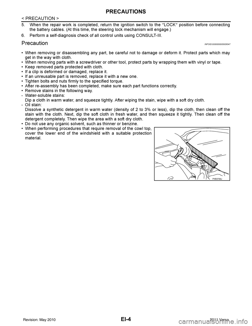
• When performing procedures that require removal of the cowl top, cover the lower end of the windshield with a suitable protection
material.
PIIB3706J
Revision: May 2010 2011 Versa
Page 2336 of 3787

EI-6
< SYMPTOM DIAGNOSIS >
SQUEAK AND RATTLE TROUBLE DIAGNOSIS
SYMPTOM DIAGNOSIS
SQUEAK AND RATTLE TROUBLE DIAGNOSIS
Work FlowINFOID:0000000005929550
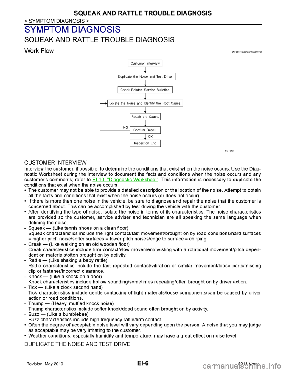
CUSTOMER INTERVIEW
Interview the customer, if possible, to determine the conditions that exis t when the noise occurs. Use the Diag-
nostic Worksheet during the interview to document the facts and conditions when the noise occurs and any
customer's comments; refer to EI-10, "
Diagnostic Worksheet". This information is necessary to duplicate the
conditions that exist when the noise occurs.
• The customer may not be able to provide a detailed description or the location of the noise. Attempt to obtain
all the facts and conditions that exist w hen the noise occurs (or does not occur).
• If there is more than one noise in the vehicle, be sure to diagnose and repair the noise that the customer is
concerned about. This can be accomplished by te st driving the vehicle with the customer.
• After identifying the type of noise, isolate the noise in terms of its characteristics. The noise characteristics
are provided so the customer, service adviser and technician are all speaking the same language when
defining the noise.
- Squeak — (Like tennis shoes on a clean floor) Squeak characteristics include the light contact/fast movement/brought on by road conditions/hard surfaces
= higher pitch noise/softer surfaces = lower pitch noises/edge to surface = chirping
- Creak — (Like walking on an old wooden floor) Creak characteristics include firm contact/slow mo vement/twisting with a rotational movement/pitch depen-
dent on materials/often brought on by activity.
- Rattle — (Like shaking a baby rattle) Rattle characteristics include the fast repeated contac t/vibration or similar movement/loose parts/missing
clip or fastener/incorrect clearance.
- Knock — (Like a knock on a door) Knock characteristics include hollow sounding/someti mes repeating/often brought on by driver action.
- Tick — (Like a clock second hand) Tick characteristics include gentle contacting of light materials/loose components/can be caused by driver
action or road conditions.
- Thump — (Heavy, muffled knock noise)
Thump characteristics include softer k nock/dead sound often brought on by activity.
- Buzz — (Like a bumblebee) Buzz characteristics include hi gh frequency rattle/firm contact.
• Often the degree of acceptable noise level will vary depending upon the person. A noise that you may judge as acceptable may be very irritating to the customer.
• Weather conditions, especially humidity and temperat ure, may have a great effect on noise level.
DUPLICATE THE NOISE AND TEST DRIVE
SBT842
Revision: May 2010 2011 Versa