2011 NISSAN LATIO warning light
[x] Cancel search: warning lightPage 3478 of 3787

PG-58
< SERVICE INFORMATION >
HARNESS
Wiring Diagram Codes (Cell Codes)
INFOID:0000000005928356
Use the chart below to find out what each wiring diagram code stands for.
Refer to the wiring diagram code in the alphabetical index to find the location (page number) of each wiring
diagram.
D4 D406 W/2 : Back door request switch C2 D413 B/1 : Rear window defogger (-)
E2 D407 W/2 : High mounted stop lamp
Code Section Wiring Diagram Name
ABS BRC Anti-lock Brake System
A/C,M MTC Manual Air Conditioner
APPS1 EC Accelerator Pedal Position Sensor
A/F EC Air Fuel Ratio Sensor 1
A/FH EC Air Fuel Ratio Sensor 1 Heater
APPS2 EC Accelerator Pedal Position Sensor
APPS3 EC Accelerator Pedal Position Sensor
ASC/BS EC ASCD Brake Switch
ASC/SW EC ASCD Steering Switch
ASCBOF EC ASCD Brake Switch
ASCIND EC ASCD Indicator
AT/IND DI A/T Indicator Lamp
AUDIO AV Audio
BACK/L LT Back-up Lamp
BA/FTS AT A/T Fluid Temperature Sensor and TCM Power Supply
B/DOOR BL Back Door Opener
BRK/SW EC Brake Switch
CAN AT CAN Communication Line
CAN CVT CAN Communication Line
CAN EC CAN Communication Line
CAN LAN CAN System
CHARGE SC Charging System
CHIME DI Warning Chime
COOL/F EC Cooling Fan Control
COMBSW LT Combination Switch
COMM AV Audio Visual Communication System
CVTIND DI CVT Indicator Lamp
D/LOCK BL Power Door Lock
DEF GW Rear Window Defogger
DTRL LT Headlamp - With Daytime Light System
ECTS EC Engine Coolant Temperature Sensor
ENGSS AT Engine Speed Signal
EPS STC Electronic Controlled Power Steering
ETC1 EC Electric Throttle Control Function
ETC2 EC Throttle Control Motor Relay
ETC3 EC Throttle Control Motor
F/FOG LT Front Fog Lamp
F/PUMP EC Fuel Pump
FTS AT A/T Fluid Temperature Sensor
FTS CVT CVT Fluid Temperature Sensor Circuit
FTTS EC Fuel Tank Temperature Sensor
FUEL EC Fuel Ignition System Function
HEATER MTC Heater System
Revision: May 2010 2011 Versa
Page 3602 of 3787

SC-24
< SERVICE INFORMATION >
CHARGING SYSTEM
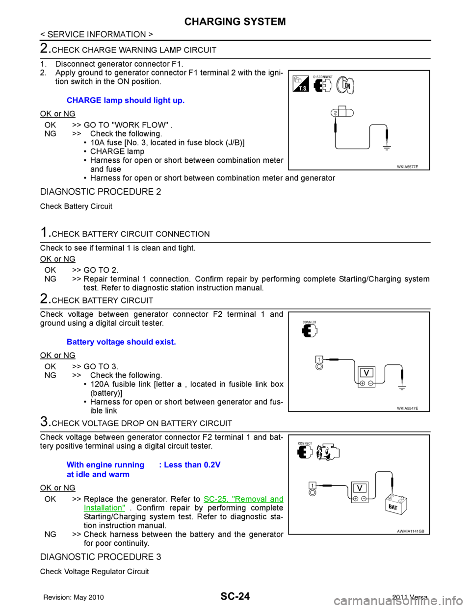
2.CHECK CHARGE WARNING LAMP CIRCUIT
1. Disconnect generator connector F1.
2. Apply ground to generator connector F1 terminal 2 with the igni- tion switch in the ON position.
OK or NG
OK >> GO TO "WORK FLOW" .
NG >> Check the following. • 10A fuse [No. 3, located in fuse block (J/B)]
• CHARGE lamp
• Harness for open or short between combination meterand fuse
• Harness for open or short between combination meter and generator
DIAGNOSTIC PROCEDURE 2
Check Battery Circuit
1.CHECK BATTERY CIRCUIT CONNECTION
Check to see if terminal 1 is clean and tight.
OK or NG
OK >> GO TO 2.
NG >> Repair terminal 1 connection. Confirm repair by performing complete Starting/Charging system test. Refer to diagnostic station instruction manual.
2.CHECK BATTERY CIRCUIT
Check voltage between generator connector F2 terminal 1 and
ground using a digital circuit tester.
OK or NG
OK >> GO TO 3.
NG >> Check the following. • 120A fusible link [letter a , located in fusible link box
(battery)]
• Harness for open or short between generator and fus- ible link
3.CHECK VOLTAGE DROP ON BATTERY CIRCUIT
Check voltage between generator connector F2 terminal 1 and bat-
tery positive terminal using a digital circuit tester.
OK or NG
OK >> Replace the generator. Refer to SC-25, "Removal and
Installation" . Confirm repair by performing complete
Starting/Charging system test. Refer to diagnostic sta-
tion instruction manual.
NG >> Check harness between the battery and the generator for poor continuity.
DIAGNOSTIC PROCEDURE 3
Check Voltage Regulator Circuit
CHARGE lamp should light up.
WKIA5577E
Battery voltage should exist.
WKIA5547E
With engine running
at idle and warm : Less than 0.2V
AWMIA1141GB
Revision: May 2010
2011 Versa
Page 3663 of 3787

TROUBLE DIAGNOSISSRS-29
< SYMPTOM DIAGNOSIS >
C
DE
F
G
I
J
K L
M A
B
SRS
N
O P
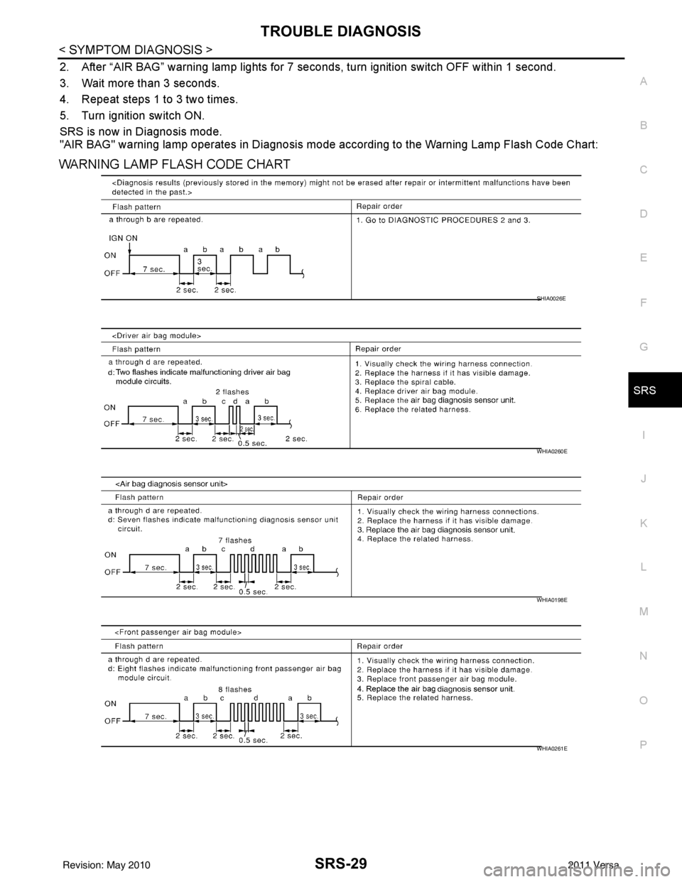
2. After “AIR BAG” warning lamp lights for 7 seconds, turn ignition switch OFF within 1 second.
3. Wait more than 3 seconds.
4. Repeat steps 1 to 3 two times.
5. Turn ignition switch ON.
SRS is now in Diagnosis mode.
"AIR BAG" warning lamp operates in Diagnosis mode according to the Warning Lamp Flash Code Chart:
WARNING LAMP FLASH CODE CHART
SHIA0026E
WHIA0260E
WHIA0198E
WHIA0261E
Revision: May 2010 2011 Versa
Page 3671 of 3787

SPIRAL CABLESRS-37
< ON-VEHICLE REPAIR >
C
DE
F
G
I
J
K L
M A
B
SRS
N
O P
SPIRAL CABLE
Removal and InstallationINFOID:0000000005931212
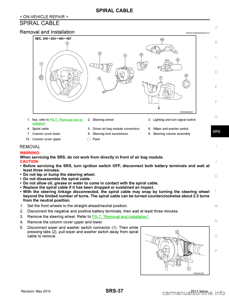
REMOVAL
WARNING:
When servicing the SRS, do not work from directly in front of air bag module.
CAUTION:
• Before servicing the SRS, turn ignition switch OFF, disconnect both battery terminals and wait at
least three minutes.
• Do not tap or bump the steering wheel.
• Do not disassemble the spiral cable.
• Do not allow oil, grease or water to co me in contact with the spiral cable.
• Replace the spiral cable if it has b een dropped or sustained an impact.
• With the steering linkage disconn ected, the spiral cable may snap by turning the steering wheel
beyond the limited number of turns. The spiral cable can be turned counterclockwise about 2.5 turns
from the neutral position.
1. Set the front wheels to the straight-ahead/neutral position.
2. Disconnect the negative and positive battery term inals, then wait at least three minutes.
3. Remove the steering wheel. Refer to PS-7, "
Removal and Installation".
4. Remove the column cover upper and lower.
5. Disconnect wiper and washer switch connector (1). Then while pressing tabs (2), pull wiper and washer switch away from spiral
cable to remove.
AWHIA0239ZZ
1. Nut, refer to PS-7, "Removal and In-
stallation"
2. Steering wheel 3. Lighting and turn signal switch
4. Spiral cable 5. Driver air bag module connectors 6. Wiper and washer switch
7. Column cover lower 8. Steering lock escutcheon 9. Steering column assembly
10. Column cover upper Pawl
WHIA0315E
Revision: May 2010 2011 Versa
Page 3688 of 3787

STC-1
STEERING
C
DE
F
H I
J
K L
M
SECTION STC
A
B
STC
N
O P
CONTENTS
STEERING CONTROL SYSTEM
EPS
BASIC INSPECTION ....... .............................
3
DIAGNOSIS AND REPAIR WORKFLOW ..... .....3
Work Flow ........................................................... ......3
SYSTEM DESCRIPTION ..............................5
EPS SYSTEM ... .............................................. .....5
System Diagram .................................................. ......5
System Description ...................................................5
Component Parts Location ........................................6
Component Description .............................................6
DIAGNOSIS SYSTEM (EPS CONTROL UNIT)
.....
8
CONSULT-III Function ........................................ ......8
DTC/CIRCUIT DIAGNOSIS ..........................9
C1601 BATTERY POWER SUPPLY ..................9
Description .......................................................... ......9
DTC Logic .................................................................9
Diagnosis Procedure .................................................9
C1604 TORQUE SENSOR .................................11
Description ..............................................................11
DTC Logic ...............................................................11
Diagnosis Procedure ...............................................11
C1606 EPS MOTOR ...........................................13
Description .......................................................... ....13
DTC Logic ...............................................................13
Diagnosis Procedure ...............................................13
Component Inspection ............................................13
C1607, C1608 EPS CONTROL UNIT ................15
Description .......................................................... ....15
DTC Logic ...............................................................15
Diagnosis Procedure ...............................................15
C1609 VEHICLE SPEED SIGNAL .....................16
Description ........................................................... ....16
DTC Logic ................................................................16
Diagnosis Procedure ...............................................16
C1610 ENGINE STATUS SIGNAL ...................17
Description ...............................................................17
DTC Logic ................................................................17
Diagnosis Procedure ...............................................17
U1000 CAN COMM CIRCUIT ...........................18
Description ...............................................................18
DTC Logic ................................................................18
Diagnosis Procedure ...............................................18
EPS WARNING LAMP ......................................19
Description ...............................................................19
Component Function Check ....................................19
Diagnosis Procedure ...............................................19
ECU DIAGNOSIS INFORMATION ..............20
EPS CONTROL UNIT .......................................20
Reference Value .................................................. ....20
Wiring Diagram - ELECTRONICALLY CON-
TROLLED POWER STEERING SYSTEM - ............
22
Fail-Safe .............................................................. ....23
DTC Inspection Priority Chart ..................................24
DTC Index ...............................................................24
SYMPTOM DIAGNOSIS ..............................25
EPS WARNING LAMP DOES NOT TURN ON ...25
Description ........................................................... ....25
Diagnosis Procedure ...............................................25
EPS WARNING LAMP DOES NOT TURN
OFF ....................................................................
26
Description ...............................................................26
Diagnosis Procedure ...............................................26
STEERING WHEEL TURNING FORCE IS
HEAVY OR LIGHT ............................................
27
Revision: May 2010 2011 Versa
Page 3714 of 3787
![NISSAN LATIO 2011 Service Repair Manual STEERING WHEEL TURNING FORCE IS HEAVY OR LIGHTSTC-27
< SYMPTOM DIAGNOSIS > [EPS]
C
D
E
F
H I
J
K L
M A
B
STC
N
O P
STEERING WHEEL TURNING FO RCE IS HEAVY OR LIGHT
DescriptionINFOID:0000000005931263
St NISSAN LATIO 2011 Service Repair Manual STEERING WHEEL TURNING FORCE IS HEAVY OR LIGHTSTC-27
< SYMPTOM DIAGNOSIS > [EPS]
C
D
E
F
H I
J
K L
M A
B
STC
N
O P
STEERING WHEEL TURNING FO RCE IS HEAVY OR LIGHT
DescriptionINFOID:0000000005931263
St](/manual-img/5/57357/w960_57357-3713.png)
STEERING WHEEL TURNING FORCE IS HEAVY OR LIGHTSTC-27
< SYMPTOM DIAGNOSIS > [EPS]
C
D
E
F
H I
J
K L
M A
B
STC
N
O P
STEERING WHEEL TURNING FO RCE IS HEAVY OR LIGHT
DescriptionINFOID:0000000005931263
Steering wheel turning force is heavy or light.
Diagnosis ProcedureINFOID:0000000005931264
1.CHECK THE ILLUMINATION OF THE EPS WARNING LAMP
Check that the EPS warning lamp turns ON when igni tion switch turns ON. Then, EPS warning lamp turns
OFF after the engine is started.
Is the inspection result normal?
YES >> GO TO 4.
NO >> GO TO 2.
2.PERFORM SELF-DIAGNOSIS
With CONSULT-III
1. Turn the ignition switch OFF to ON.
2. Perform EPS control unit self-diagnosis.
Is any DTC detected?
YES >> Check the DTC. Refer to STC-24, "DTC Index".
NO >> GO TO 3.
3.CHECK EPS CONTROL UNIT SIGNAL
With CONSULT-III
1. Start the engine. CAUTION:
Stop the vehicle.
2. Turn steering wheel from full left stop to full right stop.
3. Select “TORQUE SENSOR” of “DATA MONITOR” for EPS control unit.
Is the inspection result normal?
YES >> GO TO 5.
NO >> GO TO 4.
4.CHECK EPS MOTOR
Perform the trouble diagnosis of EPS motor. Refer to STC-13, "
Diagnosis Procedure".
Is the inspection result normal?
YES >> GO TO 5.
NO >> Repair or replace the specific malfunctioning part.
5.CHECK STEERING WH EEL TURNING FORCE
Check the steering wheel turning force. Refer to PS-6, "
On-Vehicle Inspection and Service".
Is the inspection result normal?
YES >> Inspection End
NO >> Check the steering wheel turning force for mechanical malfunction. Refer to PS-6, "
On-Vehicle
Inspection and Service".
Monitor item ConditionDisplay value
TORQUE SENSOR Steering wheel: Not steer-
ing (There is no steering
force)
Approx. 0 Nm
Steering wheel: Right turn Positive value (Nm)
Steering wheel: Left turn Negative value (Nm)
Revision: May 2010 2011 Versa