2011 NISSAN LATIO warning light
[x] Cancel search: warning lightPage 3034 of 3787

LT-2
System Description .................................................50
CAN Communication System Description ..............52
Schematic ............................................................ ...53
Wiring Diagram - TURN - ........................................54
Terminal and Reference Value for BCM .................57
How to Proceed with Trouble Diagnosis .................57
Preliminary Check ..................................................58
CONSULT-III Function (BCM) ................................58
Turn Signals Do Not Operate .................................58
Front Turn Signal Lamp Does Not Operate ............58
Rear Turn Signal Lamp Does Not Operate ............59
Hazard Warning Lamp Does Not Operate But
Turn Signal Lamp Operates ...................................
60
Turn Signal Indicator Lamp Does Not Operate ......61
Bulb Replacement for Front Turn Signal Lamp ......61
Bulb Replacement for Rear Turn Signal Lamp .......61
Removal and Installation of Front Turn Signal
Lamp .......................................................................
61
Removal and Installation of Rear Turn Signal
Lamp .......................................................................
61
LIGHTING AND TURN SIGNAL SWITCH .........62
Removal and Installation ..................................... ...62
HAZARD SWITCH .............................................63
Removal and Installation ..................................... ...63
COMBINATION SWITCH ..................................64
Wiring Diagram - COMBSW - .............................. ...64
Combination Switch Reading Function ...................64
Terminal and Reference Value for BCM .................65
CONSULT-III Function (BCM) ................................65
Combination Switch Inspection ..............................65
Removal and Installation ..................................... ...67
STOP LAMP ......................................................68
Wiring Diagram - STOP/L .................................... ...68
Wiring Diagram - STOP/L .......................................69
Bulb Replacement (High-Mounted Stop Lamp) ......69
Bulb Replacement (Rear Combination Lamp) ........70
Removal and Installation (High-Mounted Stop
Lamp) .....................................................................
70
Removal and Installation (Rear Combination
Lamp) .................................................................. ...
71
BACK-UP LAMP ................................................72
Wiring Diagram - BACK/L - .................................. ...72
Bulb Replacement ..................................................72
Removal and Installation ........................................73
PARKING, LICENSE PLATE AND TAIL
LAMPS ...............................................................
74
Component Parts and Harness Connector Loca-
tion ....................................................................... ...
74
System Description .................................................74
CAN Communication System Description ........... ...75
Schematic ...............................................................76
Wiring Diagram - TAIL/L - .......................................77
Terminal and Reference Value for BCM .............. ...80
Terminal and Reference Value for IPDM E/R .........80
How to Proceed with Trouble Diagnosis .................81
Preliminary Check ...................................................81
CONSULT-III Function (BCM) ............................. ...81
CONSULT-III Function (IPDM E/R) ........................81
Parking, License Plate and Tail Lamps Do Not Il-
luminate ..................................................................
81
Parking, License Plate and Tail Lamps Do Not
Turn OFF (After Approx. 10 Minutes) .....................
84
Bulb Replacement ................................................ ...84
Removal and Installation .........................................85
REAR COMBINATION LAMP ........................ ...87
Component .......................................................... ...87
Bulb Replacement ...................................................87
Removal and Installation .........................................88
Disassembly and Assembly ................................. ...88
INTERIOR LAMP ...............................................90
Map Lamp ............................................................ ...90
Luggage Room Lamp, Hatch Back .........................90
Trunk Room Lamp, Sedan ......................................91
Vanity Mirror Lamp ..................................................91
INTERIOR ROOM LAMP ...................................93
Component Parts and Harness Connector Loca-
tion ....................................................................... ...
93
System Description .................................................93
Schematic ...............................................................97
Wiring Diagram - INT/L - .........................................98
Terminal and Reference Value for BCM ...............102
How to Proceed with Trouble Diagnosis ...............102
Preliminary Check .................................................103
CONSULT-III Function (BCM) ............................. .103
Interior Room Lamp Control Does Not Operate
(With Map Lamp) ..................................................
104
Interior Room Lamp Control Does Not Operate
(Without Map Lamp) .............................................
106
Bulb Replacement .................................................107
Removal and Installation .......................................108
ILLUMINATION .............................................. ..109
System Description .............................................. .109
CAN Communication System Description ............110
Schematic .............................................................111
Wiring Diagram - ILL - ...........................................112
BULB SPECIFICATIONS ............................... ..116
Headlamp ............................................................. .116
Exterior Lamp ........................................................116
Interior Lamp/Illumination .....................................
Revision: May 2010 2011 Versa
Page 3047 of 3787
HEADLAMP (FOR USA)LT-15
< SERVICE INFORMATION >
C
DE
F
G H
I
J
L
M A
B
LT
N
O P
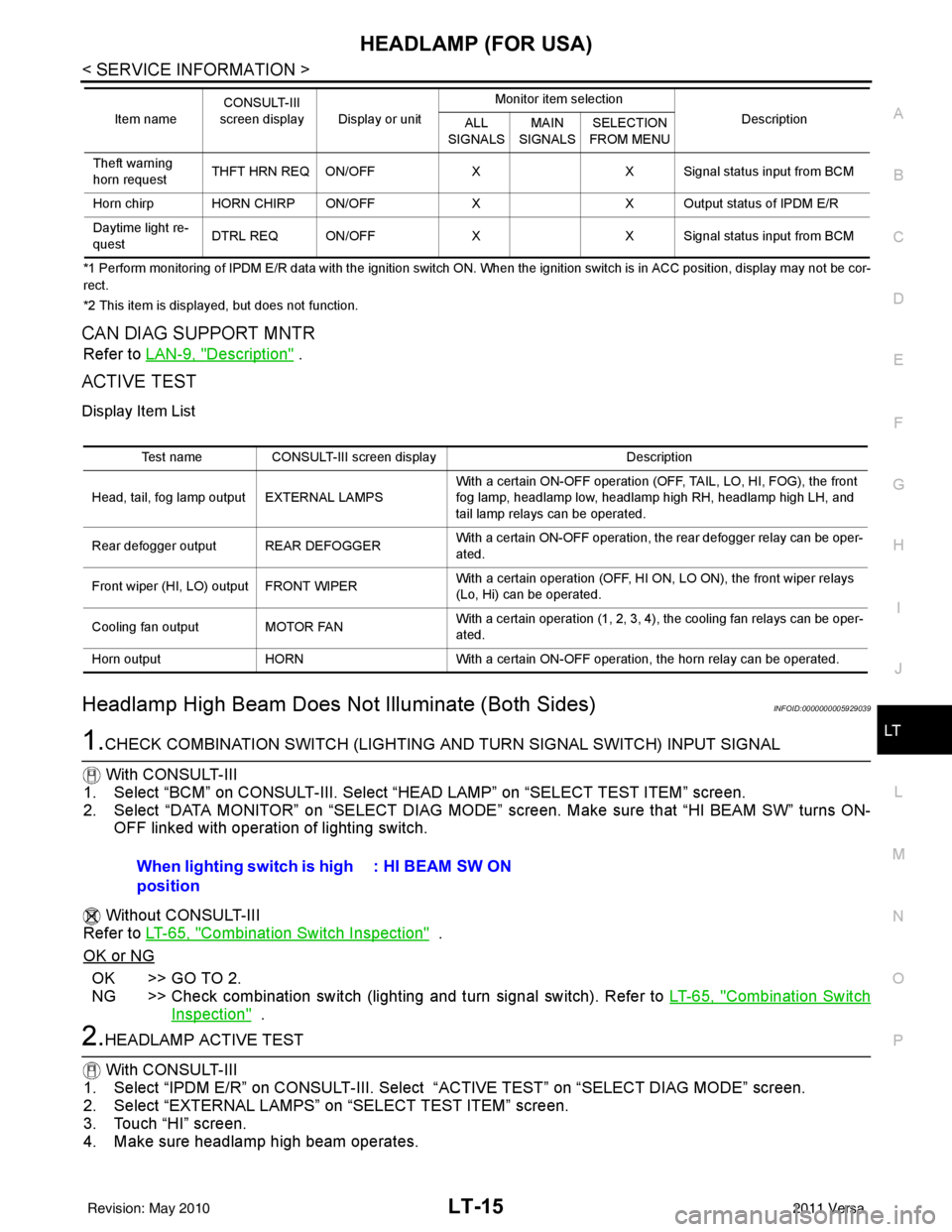
*1 Perform monitoring of IPDM E/R data with the ignition switch ON. When the ignition switch is in ACC position, display may no t be cor-
rect.
*2 This item is displayed, but does not function.
CAN DIAG SUPPORT MNTR
Refer to LAN-9, "Description" .
ACTIVE TEST
Display Item List
Headlamp High Beam Does No t Illuminate (Both Sides)INFOID:0000000005929039
1.CHECK COMBINATION SWITCH (LIGHTING AND TURN SIGNAL SWITCH) INPUT SIGNAL
With CONSULT-III
1. Select “BCM” on CONSULT-III. Select “HEAD LAMP” on “SELECT TEST ITEM” screen.
2. Select “DATA MONITOR” on “SELECT DIAG MODE” sc reen. Make sure that “HI BEAM SW” turns ON-
OFF linked with operation of lighting switch.
Without CONSULT-III
Refer to LT-65, "
Combination Switch Inspection" .
OK or NG
OK >> GO TO 2.
NG >> Check combination switch (lighting and turn signal switch). Refer to LT-65, "
Combination Switch
Inspection" .
2.HEADLAMP ACTIVE TEST
With CONSULT-III
1. Select “IPDM E/R” on CONSUL T-III. Select “ACTIVE TEST” on “SELECT DIAG MODE” screen.
2. Select “EXTERNAL LAMPS” on “SELECT TEST ITEM” screen.
3. Touch “HI” screen.
4. Make sure headlamp high beam operates.
Theft warning
horn request THFT HRN REQ ON/OFF
XX Signal status input from BCM
Horn chirp HORN CHIRP ON/OFF XX Output status of IPDM E/R
Daytime light re-
quest DTRL REQ ON/OFF
XX Signal status input from BCM
Item name
CONSULT-III
screen display Display or unit Monitor item selection
Description
ALL
SIGNALS MAIN
SIGNALS SELECTION
FROM MENU
Test name CONSULT-III screen display Description
Head, tail, fog lamp output EXTERNAL LAMPS With a certain ON-OFF operation (OFF, TAIL, LO, HI, FOG), the front
fog lamp, headlamp low, headlamp high RH, headlamp high LH, and
tail lamp relays can be operated.
Rear defogger output REAR DEFOGGER With a certain ON-OFF operation, the rear defogger relay can be oper-
ated.
Front wiper (HI, LO) output FRONT WIPER With a certain operation (OFF, HI ON, LO ON), the front wiper relays
(Lo, Hi) can be operated.
Cooling fan output MOTOR FAN With a certain operation (1, 2, 3, 4), the cooling fan relays can be oper-
ated.
Horn output HORN With a certain ON-OFF operation, the horn relay can be operated.
When lighting switch is high
position : HI BEAM SW ON
Revision: May 2010
2011 Versa
Page 3082 of 3787
LT-50
< SERVICE INFORMATION >
TURN SIGNAL AND HAZARD WARNING LAMPS
TURN SIGNAL AND HAZARD WARNING LAMPS
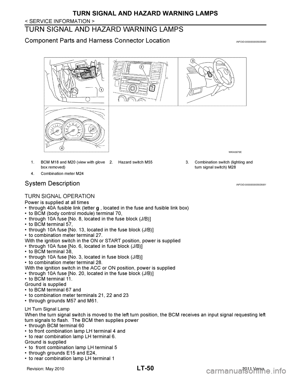
Component Parts and Harn ess Connector LocationINFOID:0000000005929080
System DescriptionINFOID:0000000005929081
TURN SIGNAL OPERATION
Power is supplied at all times
• through 40A fusible link (letter g , located in the fuse and fusible link box)
• to BCM (body control module) terminal 70,
• through 10A fuse [No. 8, located in the fuse block (J/B)]
• to BCM terminal 57,
• through 10A fuse [No. 13, located in the fuse block (J/B)]
• to combination meter terminal 27.
With the ignition switch in the ON or START position, power is supplied
• through 10A fuse [No. 6, located in fuse block (J/B)]
• to BCM terminal 38,
• through 10A fuse [No. 3, located in fuse block (J/B)]
• to combination meter terminal 28.
With the ignition switch in the ACC or ON position, power is supplied
• through 10A fuse [No. 20, located in the fuse block (J/B)]
• to BCM terminal 11.
Ground is supplied
• to BCM terminal 67 and
• to combination meter terminals 21, 22 and 23
• through grounds M57 and M61.
LH Turn Signal Lamp
When the turn signal switch is moved to the left turn position, the BCM receives an input signal requesting left
turn signals to flash. The BCM then supplies power
• through BCM terminal 60
• to front combination lamp LH terminal 4 and
• to rear combination lamp LH terminal 6.
Ground is supplied
• to front combination lamp LH terminal 5
• through grounds E15 and E24,
• to rear combination lamp LH terminal 1
1. BCM M18 and M20 (view with glove
box removed) 2. Hazard switch M55 3. Combination switch (lighting and
turn signal switch) M28
4. Combination meter M24
WKIA5679E
Revision: May 2010 2011 Versa
Page 3090 of 3787
LT-58
< SERVICE INFORMATION >
TURN SIGNAL AND HAZARD WARNING LAMPS
3. Perform the preliminary check. Refer to LT-58, "Preliminary Check" .
4. Check symptom and repair or replace the cause of the malfunction.
5. Do turn signal and hazard warning lamps operate no rmally? If YES, GO TO 6. If NO, GO TO 4.
6. INSPECTION END
Preliminary CheckINFOID:0000000005929087
CHECK POWER SUPPLY AND GROUND CIRCUIT FOR BCM
Refer to BCS-16, "BCM Power Supply and Ground Circuit Inspection" .
CONSULT-III Function (BCM)INFOID:0000000005929088
Refer to BCS-17, "CONSULT-III Function (BCM)" .
Turn Signals Do Not OperateINFOID:0000000005929089
1.CHECK COMBINATION SWITCH (LIGHTING AND TURN SIGNAL SWITCH) INPUT SIGNAL
With CONSULT-III
1. Select “BCM” on CONSULT-III. Select “FLASHER” on “SELECT TEST ITEM” screen.
2. Select “DATA MONITOR” on “SELECT DIAG MODE ” screen. Make sure that “TURN SIGNAL R” and
“TURN SIGNAL L” turns ON-OFF linked with operation of lighting switch.
Without CONSULT-III
Refer to LT-65, "
Combination Switch Inspection" .
OK or NG
OK >> Replace the BCM. BCS-19, "Removal and Installation of BCM"
NG >> Check combination switch (lighting and turn signal switch). Refer to LT-65, "Combination Switch
Inspection" .
Front Turn Signal Lamp Does Not OperateINFOID:0000000005929090
1.CHECK BULB
Verify the bulb standard of each turn signal lamp is correct. Refer to LT-116, "
Exterior Lamp" .
OK or NG
OK >> GO TO 2.
NG >> Replace turn signal lamp bulb. Refer to LT-61, "
Bulb Replacement for Front Turn Signal Lamp" .
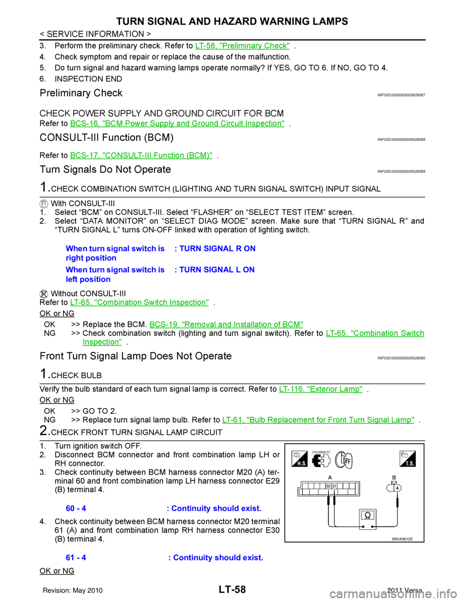
2.CHECK FRONT TURN SIGNAL LAMP CIRCUIT
1. Turn ignition switch OFF.
2. Disconnect BCM connector and front combination lamp LH or RH connector.
3. Check continuity between BCM harness connector M20 (A) ter- minal 60 and front combination lamp LH harness connector E29
(B) terminal 4.
4. Check continuity between BCM harness connector M20 terminal 61 (A) and front combination lamp RH harness connector E30
(B) terminal 4.
OK or NG
When turn signal switch is
right position : TURN SIGNAL R ON
When turn signal switch is
left position : TURN SIGNAL L ON
60 - 4
: Continuity should exist.
61 - 4 : Continuity should exist.
WKIA5612E
Revision: May 2010 2011 Versa
Page 3150 of 3787
![NISSAN LATIO 2011 Service Repair Manual LU-2
< PRECAUTION >[HR16DE]
PRECAUTIONS
PRECAUTION
PRECAUTIONS
Precaution for Supplemental Restraint Syst
em (SRS) "AIR BAG" and "SEAT BELT
PRE-TENSIONER"
INFOID:0000000005928680
The Supplemental Res NISSAN LATIO 2011 Service Repair Manual LU-2
< PRECAUTION >[HR16DE]
PRECAUTIONS
PRECAUTION
PRECAUTIONS
Precaution for Supplemental Restraint Syst
em (SRS) "AIR BAG" and "SEAT BELT
PRE-TENSIONER"
INFOID:0000000005928680
The Supplemental Res](/manual-img/5/57357/w960_57357-3149.png)
LU-2
< PRECAUTION >[HR16DE]
PRECAUTIONS
PRECAUTION
PRECAUTIONS
Precaution for Supplemental Restraint Syst
em (SRS) "AIR BAG" and "SEAT BELT
PRE-TENSIONER"
INFOID:0000000005928680
The Supplemental Restraint System such as “A IR BAG” and “SEAT BELT PRE-TENSIONER”, used along
with a front seat belt, helps to reduce the risk or severity of injury to the driver and front passenger for certain
types of collision. This system includes seat belt switch inputs and dual stage front air bag modules. The SRS
system uses the seat belt switches to determine the front air bag deployment, and may only deploy one front
air bag, depending on the severity of a collision and w hether the front occupants are belted or unbelted.
Information necessary to service the system safely is included in the SRS and SB section of this Service Man-
ual.
WARNING:
• To avoid rendering the SRS inopera tive, which could increase the risk of personal injury or death in
the event of a collision which would result in air bag inflation, all maintenance must be performed by
an authorized NISSAN/INFINITI dealer.
• Improper maintenance, including incorrect removal and installation of the SRS can lead to personal
injury caused by unintent ional activation of the system. For re moval of Spiral Cable and Air Bag
Module, see the SRS section.
• Do not use electrical test equipmen t on any circuit related to the SRS unless instructed to in this
Service Manual. SRS wiring harn esses can be identified by yellow and/or orange harnesses or har-
ness connectors.
PRECAUTIONS WHEN USING POWER TOOLS (AIR OR ELECTRIC) AND HAMMERS
WARNING:
• When working near the Airbag Diagnosis Sensor Unit or other Airbag System sensors with the Igni-
tion ON or engine running, DO NOT use air or electri c power tools or strike near the sensor(s) with a
hammer. Heavy vibration could activate the sensor( s) and deploy the air bag(s), possibly causing
serious injury.
• When using air or electric power tools or hammers , always switch the Ignition OFF, disconnect the
battery, and wait at least 3 minu tes before performing any service.
Precaution for Liquid GasketINFOID:0000000005928682
REMOVAL OF LIQUID GASKET SEALING
• After removing nuts and bolts, separate the mating surface, using Tool and remove old liquid gasket sealing.
CAUTION:
Be careful not to damage the mating surfaces.
• Tap Tool to insert it (1), and then slide it by tapping on the side (2)
as shown.
• In areas where Tool is difficult to use, use plastic hammer to lightly tap the parts, to remove it.
CAUTION:
If for some unavoidable reason suitable tool such as screw-
driver is used, be careful no t to damage the mating surfaces.
LIQUID GASKET APPLICATION PROCEDURE
Tool number : KV10111100 (J-37228)
WBIA0566E
Revision: May 2010 2011 Versa
Page 3440 of 3787

PG-20
< SERVICE INFORMATION >
IPDM E/R (INTELLIGENT POWER DISTRIBUTION MODULE ENGINE ROOM)
*1 Perform monitoring of IPDM E/R data with the ignition switch ON. When the ignition switch is in ACC position, display may no t be cor-
rect.
*2 This item is displayed, but does not function.
CAN DIAG SUPPORT MNTR
Refer to LAN-9, "Description" .
ACTIVE TEST
Display Item List
Auto Active TestINFOID:0000000005928347
DESCRIPTION
• In auto active test mode, operation inspection can be performed when IPDM E/R sends a drive signal to the
following systems:
- Rear window defogger
- Front wipers
- Tail, license and parking lamps
- Daytime lamp system (Canada only)
- Front fog lamps
- Headlamps (High, Low)
- A/C compressor (magnet clutch)
- Cooling fan
OPERATION PROCEDURE
1. Close hood and front door RH, and lift wiper arms away from windshield (to prevent glass damage by wiper operation).
NOTE:
When auto active test is performed with hood opened, sprinkle water on windshield beforehand.
2. Turn ignition switch OFF.
3. Turn ignition switch ON and, within 20 seconds, pres s front door switch LH 10 times. Then turn ignition
switch OFF.
4. Turn ignition switch ON within 10 seconds after ignition switch OFF.
5. When auto active test mode is actuated, horn chirps once.
6. After a series of operations is repeated three times, auto active test is completed.
Theft warning
horn request THFT HRN REQ ON/OFF
XX Signal status input from BCM
Horn chirp HORN CHIRP ON/OFF XX Output status of IPDM E/R
Daytime light re-
quest DTRL REQ ON/OFF
XX Signal status input from BCM
Item name
CONSULT-III
screen display Display or unit Monitor item selection
Description
ALL
SIGNALS MAIN
SIGNALS SELECTION
FROM MENU
Test name CONSULT-III screen display Description
Head, tail, fog lamp output EXTERNAL LAMPS With a certain ON-OFF operation (OFF, TAIL, LO, HI, FOG), the front
fog lamp, headlamp low, headlamp high RH, headlamp high LH, and
tail lamp relays can be operated.
Rear defogger output REAR DEFOGGER With a certain ON-OFF operation, the rear defogger relay can be oper-
ated.
Front wiper (HI, LO) output FRONT WIPER With a certain operation (OFF, HI ON, LO ON), the front wiper relays
(Lo, Hi) can be operated.
Cooling fan output MOTOR FAN With a certain operation (1, 2, 3, 4), the cooling fan relays can be oper-
ated.
Horn output HORN With a certain ON-OFF operation, the horn relay can be operated.
Revision: May 2010 2011 Versa
Page 3441 of 3787
IPDM E/R (INTELLIGENT POWER DISTRIBUTION MODULE ENGINE ROOM)
PG-21
< SERVICE INFORMATION >
C
D E
F
G H
I
J
L
M A
B
PG
N
O P
NOTE:
When auto active test mode has to be cancelled halfway, turn ignition switch OFF.
CAUTION:
Be sure to perform BL-44, "
Door Switch Check (Hatchback)" or BL-47, "Door Switch Check
(Sedan)" when the auto active test cannot be performed.
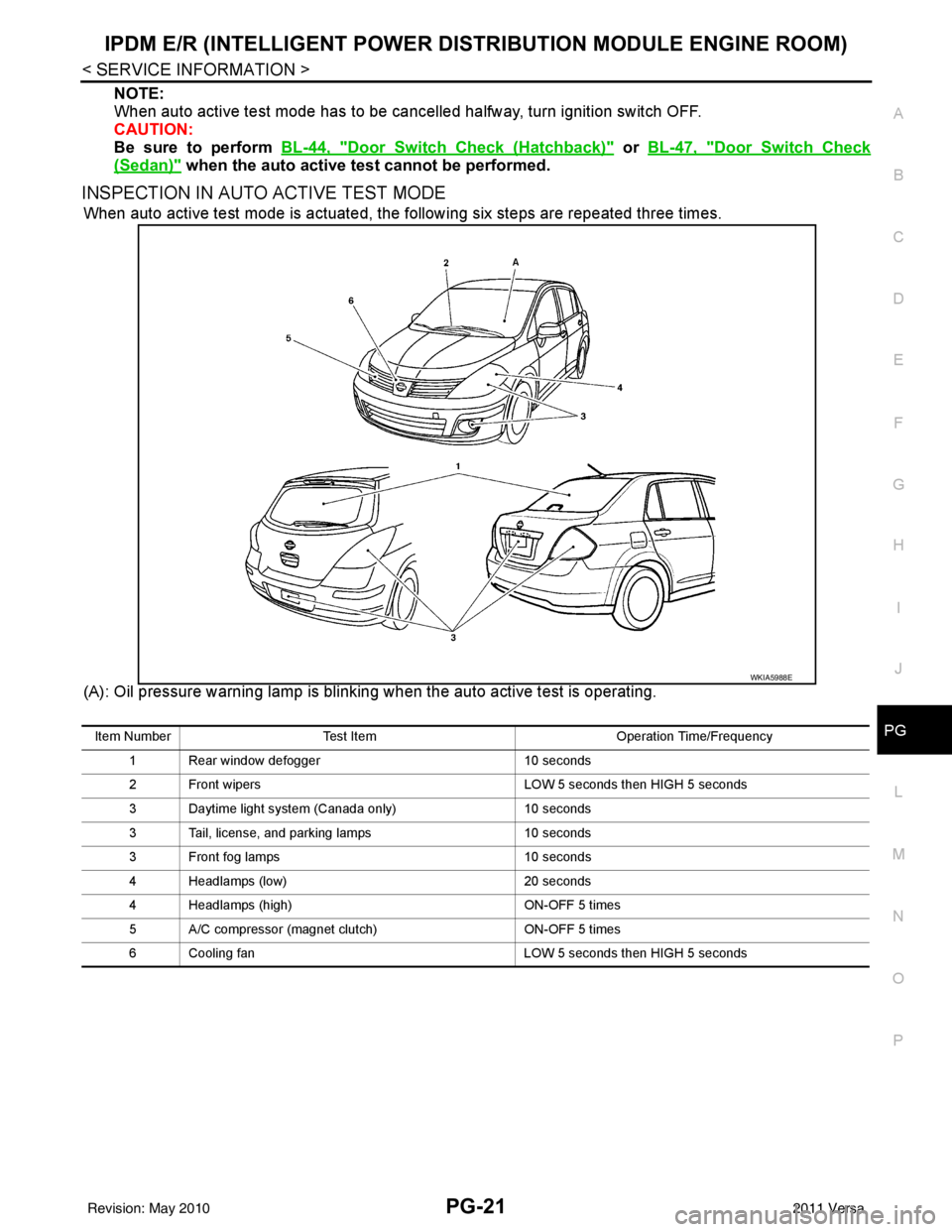
INSPECTION IN AUTO ACTIVE TEST MODE
When auto active test mode is actuated, the following six steps are repeated three times.
(A): Oil pressure warning lamp is blinking when the auto active test is operating.
WKIA5988E
Item Number Test Item Operation Time/Frequency
1 Rear window defogger 10 seconds
2 Front wipers LOW 5 seconds then HIGH 5 seconds
3 Daytime light system (Canada only) 10 seconds
3 Tail, license, and parking lamps 10 seconds
3 Front fog lamps 10 seconds
4 Headlamps (low) 20 seconds
4 Headlamps (high) ON-OFF 5 times
5 A/C compressor (magnet clutch) ON-OFF 5 times
6 Cooling fan LOW 5 seconds then HIGH 5 seconds
Revision: May 2010 2011 Versa
Page 3442 of 3787
PG-22
< SERVICE INFORMATION >
IPDM E/R (INTELLIGENT POWER DISTRIBUTION MODULE ENGINE ROOM)
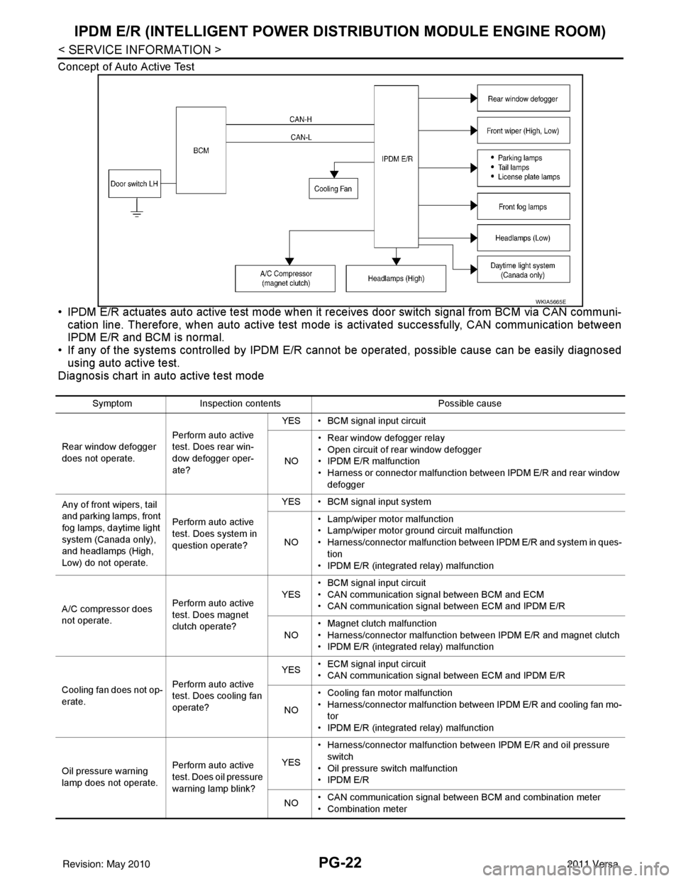
Concept of Auto Active Test
• IPDM E/R actuates auto active test mode when it re ceives door switch signal from BCM via CAN communi-
cation line. Therefore, when auto active test mode is activated successfully, CAN communication between
IPDM E/R and BCM is normal.
• If any of the systems controll ed by IPDM E/R cannot be operated, possible cause can be easily diagnosed
using auto active test.
Diagnosis chart in auto active test mode
WKIA5665E
Symptom Inspection contents Possible cause
Rear window defogger
does not operate. Perform auto active
test. Does rear win-
dow defogger oper-
ate?YES • BCM signal input circuit
NO • Rear window defogger relay
• Open circuit of rear window defogger
•IPDM E/R malfunction
• Harness or connector malfunction between IPDM E/R and rear window
defogger
Any of front wipers, tail
and parking lamps, front
fog lamps, daytime light
system (Canada only),
and headlamps (High,
Low) do not operate. Perform auto active
test. Does system in
question operate?YES • BCM signal input system
NO • Lamp/wiper motor malfunction
• Lamp/wiper motor ground circuit malfunction
• Harness/connector malfunction between IPDM E/R and system in ques-
tion
• IPDM E/R (integrated relay) malfunction
A/C compressor does
not operate. Perform auto active
test. Does magnet
clutch operate?YES
• BCM signal input circuit
• CAN communication signal between BCM and ECM
• CAN communication signal between ECM and IPDM E/R
NO • Magnet clutch malfunction
• Harness/connector malfunction between IPDM E/R and magnet clutch
• IPDM E/R (integrated relay) malfunction
Cooling fan does not op-
erate. Perform auto active
test. Does cooling fan
operate?YES
• ECM signal input circuit
• CAN communication signal between ECM and IPDM E/R
NO • Cooling fan motor malfunction
• Harness/connector malfunction between IPDM E/R and cooling fan mo-
tor
• IPDM E/R (integrated relay) malfunction
Oil pressure warning
lamp does not operate. Perform auto active
test. Does oil pressure
warning lamp blink?YES
• Harness/connector malfunction between IPDM E/R and oil pressure
switch
• Oil pressure switch malfunction
•IPDM E/R
NO • CAN communication signal between BCM and combination meter
• Combination meter
Revision: May 2010
2011 Versa