2011 NISSAN LATIO hatch back
[x] Cancel search: hatch backPage 632 of 3787
BL-122
< SERVICE INFORMATION >
INTELLIGENT KEY SYSTEM
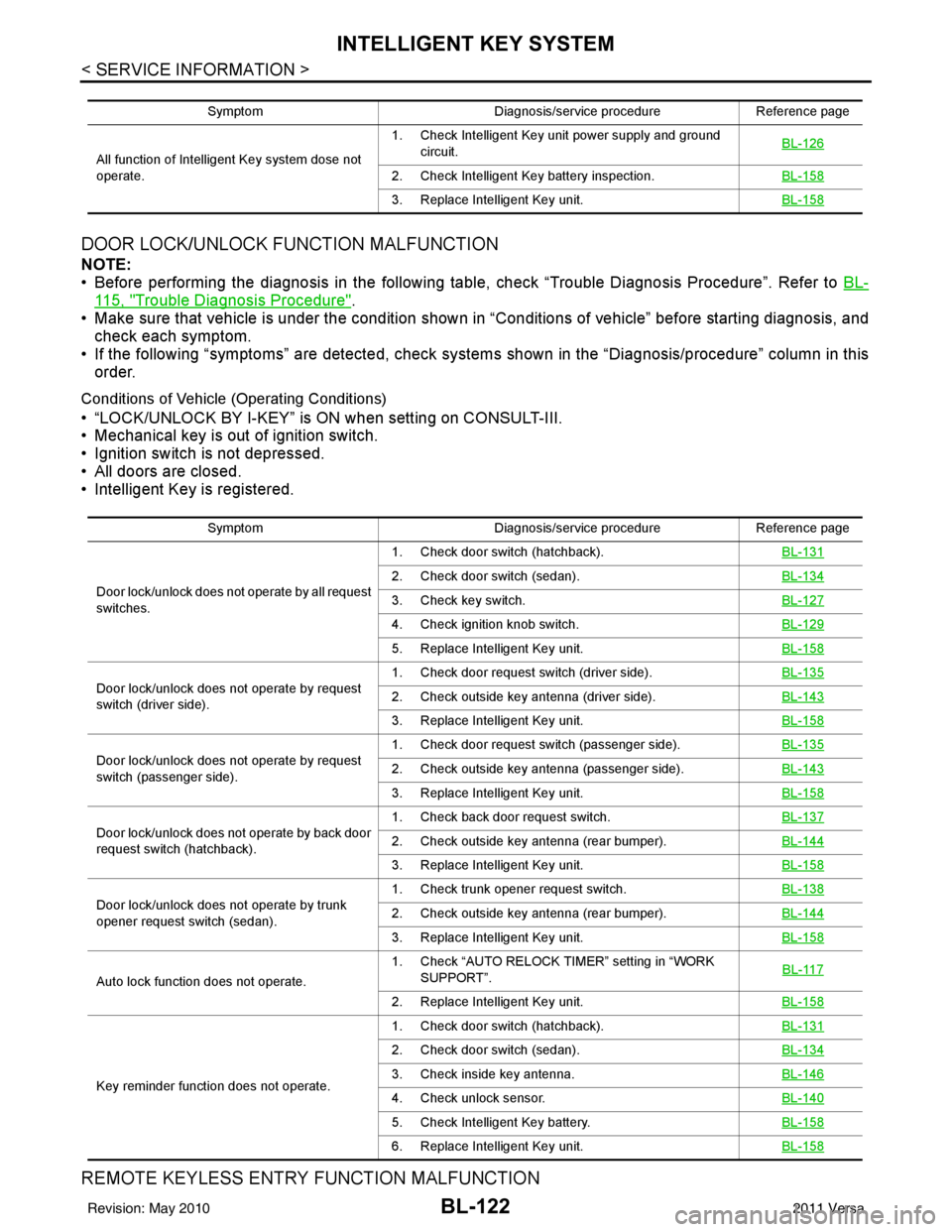
DOOR LOCK/UNLOCK FUNCTION MALFUNCTION
NOTE:
• Before performing the diagnosis in the following table, check “Trouble Diagnosis Procedure”. Refer to BL-
115, "Trouble Diagnosis Procedure".
• Make sure that vehicle is under the condition shown in “Conditions of vehicle” before starting diagnosis, and
check each symptom.
• If the following “symptoms” are detected, check system s shown in the “Diagnosis/procedure” column in this
order.
Conditions of Vehicle (Operating Conditions)
• “LOCK/UNLOCK BY I-KEY” is ON when setting on CONSULT-III.
• Mechanical key is out of ignition switch.
• Ignition switch is not depressed.
• All doors are closed.
• Intelligent Key is registered.
REMOTE KEYLESS ENTRY FUNCTION MALFUNCTION
Symptom Diagnosis/service procedureReference page
All function of Intelligent Key system dose not
operate. 1. Check Intelligent Key unit power supply and ground
circuit. BL-126
2. Check Intelligent Key battery inspection.
BL-158
3. Replace Intelligent Key unit.BL-158
SymptomDiagnosis/service procedureReference page
Door lock/unlock does not operate by all request
switches. 1. Check door switch (hatchback).
BL-131
2. Check door switch (sedan).BL-134
3. Check key switch.BL-127
4. Check ignition knob switch.BL-129
5. Replace Intelligent Key unit.BL-158
Door lock/unlock does not operate by request
switch (driver side).1. Check door request switch (driver side).
BL-1352. Check outside key antenna (driver side).BL-143
3. Replace Intelligent Key unit.BL-158
Door lock/unlock does not operate by request
switch (passenger side).1. Check door request switch (passenger side).
BL-1352. Check outside key antenna (passenger side).BL-143
3. Replace Intelligent Key unit.BL-158
Door lock/unlock does not operate by back door
request switch (hatchback).1. Check back door request switch.
BL-1372. Check outside key antenna (rear bumper).BL-144
3. Replace Intelligent Key unit.BL-158
Door lock/unlock does not operate by trunk
opener request switch (sedan).1. Check trunk opener request switch.
BL-1382. Check outside key antenna (rear bumper).BL-144
3. Replace Intelligent Key unit.BL-158
Auto lock function does not operate.1. Check “AUTO RELOCK TI
MER” setting in “WORK
SUPPORT”. BL-117
2. Replace Intelligent Key unit.
BL-158
Key reminder function does not operate.1. Check door switch (hatchback).
BL-131
2. Check door switch (sedan).BL-134
3. Check inside key antenna.BL-146
4. Check unlock sensor.BL-140
5. Check Intelligent Key battery.BL-158
6. Replace Intelligent Key unit.BL-158
Revision: May 2010 2011 Versa
Page 633 of 3787

INTELLIGENT KEY SYSTEMBL-123
< SERVICE INFORMATION >
C
DE
F
G H
J
K L
M A
B
BL
N
O P
NOTE:
• Before performing the diagnosis in the following table, check “Trouble Diagnosis Procedure”. Refer to BL-
115, "Trouble Diagnosis Procedure".
• Make sure that vehicle is under the condition shown in “Conditions of vehicle” before starting diagnosis, and
check each symptom.
• If the following “symptoms” are detected, check syst ems shown in the “Diagnosis/service procedure” column
in this order.
Conditions of Vehicle (Operating Conditions)
• Ignition switch is not depressed.
• All doors are closed.
HAZARD AND BUZZER REMINDER FUNCTION MALFUNCTION
NOTE:
• Before performing the diagnosis in the following table, check “Trouble Diagnosis Procedure”. Refer to BL-
115, "Trouble Diagnosis Procedure".
• Make sure that vehicle is under the condition shown in “Conditions of vehicle” before starting diagnosis, and
check each symptom.
• If the following “symptoms” are detected, check syst ems shown in the “Diagnosis/service procedure” column
in this order.
Conditions of Vehicle (Operating Conditions)
• Ignition switch is not depressed.
• All doors are closed.
Symptom Diagnosis/service procedure Reference
page
All of the remote keyless entry functions do
not operate. 1. Check Intelligent Key unit power supply and ground circuit.
BL-126
2. Check key switch (BCM input).BL-128
3. Check Intelligent Key battery.BL-158
4. Remote Keyless Entry function inspection.BL-158
5. Replace Intelligent Key unit.BL-158
Auto lock function does not operate.1. Check “AUTO RELOCK TIMER”
setting in “WORK SUPPORT”. BL-1172. Replace Intelligent Key unit. BL-158
Key reminder function does not operate.1. Check door switch (hatchback).
BL-131
2. Check door switch (sedan).BL-134
3. Check inside key antenna.BL-146
4. Check unlock sensor.BL-140
5. Check Intelligent Key battery.BL-158
6. Replace Intelligent Key unit.BL-158
Panic alarm function does not operate.1. Check “PANIC ALARM DELAY” setting in “WORK SUPPORT”.
BL-117
2. Check Intelligent Key battery inspection.BL-158
3. Check horn function.BL-157
4. Check headlamp function.BL-157
5. Check key switch.BL-127
6. Check ignition knob switch.BL-129
7. Replace Intelligent Key unit.BL-158
SymptomDiagnosis/service procedure Reference page
Hazard reminder does not operate by request
switch.
(Buzzer reminder operate). 1. Check “HAZARD ANSWER BACK” setting in “WORK
SUPPORT”. BL-117
2. Check hazard function with hazard switch.
BL-156
3. Replace Intelligent Key unit.BL-158
Revision: May 2010 2011 Versa
Page 634 of 3787
BL-124
< SERVICE INFORMATION >
INTELLIGENT KEY SYSTEM
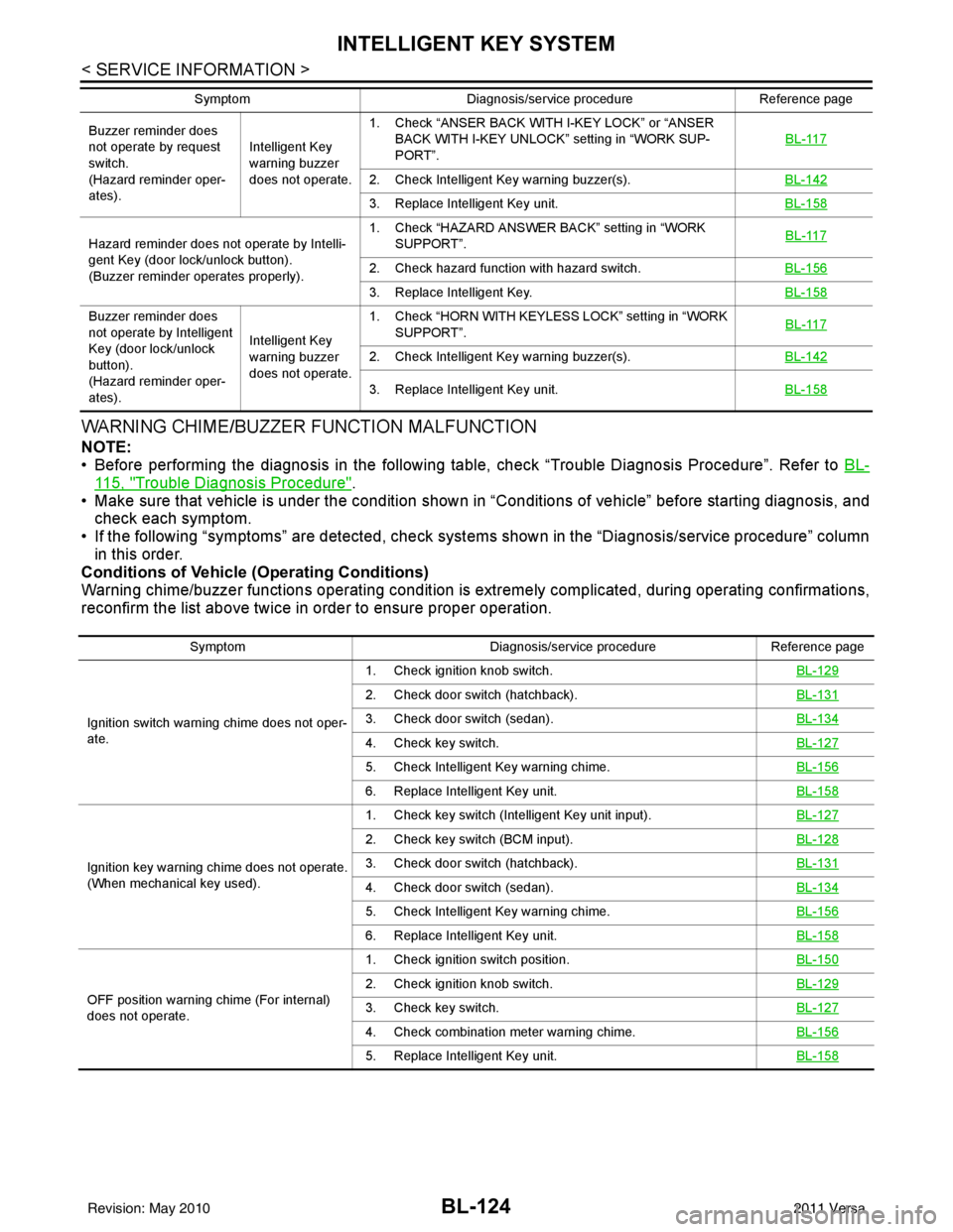
WARNING CHIME/BUZZER FUNCTION MALFUNCTION
NOTE:
• Before performing the diagnosis in the following table, check “Trouble Diagnosis Procedure”. Refer to BL-
115, "Trouble Diagnosis Procedure".
• Make sure that vehicle is under the condition shown in “Conditions of vehicle” before starting diagnosis, and
check each symptom.
• If the following “symptoms” are detected, check syst ems shown in the “Diagnosis/service procedure” column
in this order.
Conditions of Vehicle (Operating Conditions)
Warning chime/buzzer functions operating condition is extremely complicated, during operating confirmations,
reconfirm the list above twice in order to ensure proper operation.
Buzzer reminder does
not operate by request
switch.
(Hazard reminder oper-
ates). Intelligent Key
warning buzzer
does not operate.1. Check “ANSER BACK WITH I-KEY LOCK” or “ANSER
BACK WITH I-KEY UNLOCK” setting in “WORK SUP-
PORT”. BL-117
2. Check Intelligent Key warning buzzer(s).
BL-142
3. Replace Intelligent Key unit.BL-158
Hazard reminder does not operate by Intelli-
gent Key (door lock/unlock button).
(Buzzer reminder operates properly).1. Check “HAZARD ANSWER BACK” setting in “WORK
SUPPORT”. BL-117
2. Check hazard function with hazard switch.
BL-156
3. Replace Intelligent Key.BL-158
Buzzer reminder does
not operate by Intelligent
Key (door lock/unlock
button).
(Hazard reminder oper-
ates).Intelligent Key
warning buzzer
does not operate.1. Check “HORN WITH KEYLESS LOCK” setting in “WORK
SUPPORT”. BL-117
2. Check Intelligent Key warning buzzer(s).
BL-142
3. Replace Intelligent Key unit.BL-158
SymptomDiagnosis/service procedure Reference page
Symptom Diagnosis/service procedureReference page
Ignition switch warning chime does not oper-
ate. 1. Check ignition knob switch.
BL-129
2. Check door switch (hatchback).BL-131
3. Check door switch (sedan).BL-134
4. Check key switch.BL-127
5. Check Intelligent Key warning chime.BL-156
6. Replace Intelligent Key unit.BL-158
Ignition key warning chime does not operate.
(When mechanical key used).1. Check key switch (Intelligent Key unit input).
BL-127
2. Check key switch (BCM input).BL-128
3. Check door switch (hatchback).BL-131
4. Check door switch (sedan).BL-134
5. Check Intelligent Key warning chime.BL-156
6. Replace Intelligent Key unit.BL-158
OFF position warning chime (For internal)
does not operate.1. Check ignition switch position.
BL-150
2. Check ignition knob switch.BL-129
3. Check key switch.BL-127
4. Check combination meter warning chime.BL-156
5. Replace Intelligent Key unit.BL-158
Revision: May 2010 2011 Versa
Page 635 of 3787
INTELLIGENT KEY SYSTEMBL-125
< SERVICE INFORMATION >
C
DE
F
G H
J
K L
M A
B
BL
N
O P
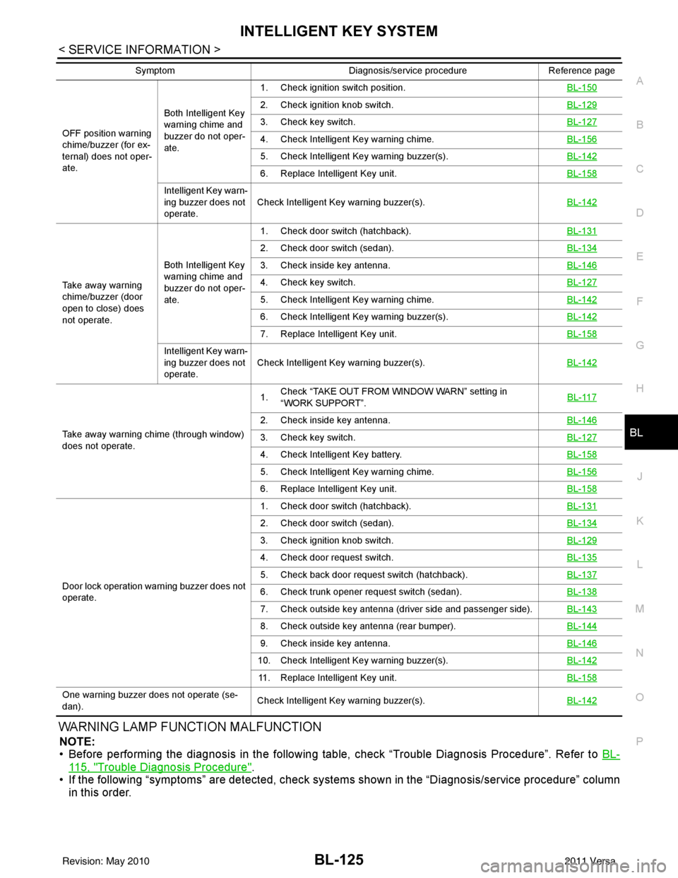
WARNING LAMP FUNCTION MALFUNCTION
NOTE:
• Before performing the diagnosis in the following table, check “Trouble Diagnosis Procedure”. Refer to BL-
115, "Trouble Diagnosis Procedure".
• If the following “symptoms” are detected, check syst ems shown in the “Diagnosis/service procedure” column
in this order.
OFF position warning
chime/buzzer (for ex-
ternal) does not oper-
ate. Both Intelligent Key
warning chime and
buzzer do not oper-
ate.1. Check ignition switch position.
BL-150
2. Check ignition knob switch.BL-129
3. Check key switch.BL-127
4. Check Intelligent Key warning chime.BL-156
5. Check Intelligent Key warning buzzer(s). BL-142
6. Replace Intelligent Key unit. BL-158
Intelligent Key warn-
ing buzzer does not
operate.Check Intelligent Key warning buzzer(s).
BL-142
Take away warning
chime/buzzer (door
open to close) does
not operate.Both Intelligent Key
warning chime and
buzzer do not oper-
ate.1. Check door switch (hatchback).
BL-131
2. Check door switch (sedan).BL-134
3. Check inside key antenna.BL-146
4. Check key switch.BL-127
5. Check Intelligent Key warning chime.BL-142
6. Check Intelligent Key warning buzzer(s). BL-142
7. Replace Intelligent Key unit. BL-158
Intelligent Key warn-
ing buzzer does not
operate.Check Intelligent Key warning buzzer(s).
BL-142
Take away warning chime (through window)
does not operate.1.
Check “TAKE OUT FROM WINDOW WARN” setting in
“WORK SUPPORT”.
BL-117
2. Check inside key antenna.
BL-146
3. Check key switch.BL-127
4. Check Intelligent Key battery.BL-158
5. Check Intelligent Key warning chime.BL-156
6. Replace Intelligent Key unit.BL-158
Door lock operation warning buzzer does not
operate.1. Check door switch (hatchback).
BL-131
2. Check door switch (sedan).BL-134
3. Check ignition knob switch.BL-129
4. Check door request switch.BL-135
5. Check back door request switch (hatchback).BL-137
6. Check trunk opener request switch (sedan).BL-138
7. Check outside key antenna (driver side and passenger side).BL-143
8. Check outside key antenna (rear bumper).BL-144
9. Check inside key antenna.BL-146
10. Check Intelligent Key warning buzzer(s). BL-142
11. Replace Intelligent Key unit.BL-158
One warning buzzer does not operate (se-
dan).Check Intelligent Key warning buzzer(s).
BL-142
SymptomDiagnosis/service procedureReference page
Revision: May 2010 2011 Versa
Page 641 of 3787
INTELLIGENT KEY SYSTEMBL-131
< SERVICE INFORMATION >
C
DE
F
G H
J
K L
M A
B
BL
N
O P
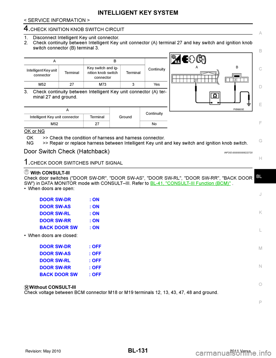
4.CHECK IGNITION KN OB SWITCH CIRCUIT
1. Disconnect Intelligent Key unit connector.
2. Check continuity between Intelligent Key unit c onnector (A) terminal 27 and key switch and ignition knob
switch connector (B) terminal 3.
3. Check continuity between Intelligent Key unit connector (A) ter- minal 27 and ground.
OK or NG
OK >> Check the condition of harness and harness connector.
NG >> Repair or replace harness between Intelligent Key unit and key switch and ignition knob switch.
Door Switch Check (Hatchback)INFOID:0000000006222720
1.CHECK DOOR SWITCHES INPUT SIGNAL
With CONSULT-III
Check door switches ("DOOR SW-DR", "DOOR SW-AS", "DOOR SW-RL", "DOOR SW-RR", "BACK DOOR
SW") in DATA MONITOR mode with CONSULT–III. Refer to BL-41, "
CONSULT-III Function (BCM)" .
• When doors are open:
• When doors are closed:
Without CONSULT-III
Check voltage between BCM connector M18 or M19 terminals 12, 13, 43, 47, 48 and ground.
AB
Continuity
Intelligent Key unit
connector Te r m i n a lKey switch and ig-
nition knob switch
connector Te r m i n a l
M52 27M73 3Yes
A GroundContinuity
Intelligent Key unit connector Terminal
M52 27 No
PIIB6605E
DOOR SW-DR : ON
DOOR SW-AS : ON
DOOR SW-RL : ON
DOOR SW-RR : ON
BACK DOOR SW : ON
DOOR SW-DR : OFF
DOOR SW-AS : OFF
DOOR SW-RL : OFF
DOOR SW-RR : OFF
BACK DOOR SW : OFF
Revision: May 2010 2011 Versa
Page 647 of 3787
INTELLIGENT KEY SYSTEMBL-137
< SERVICE INFORMATION >
C
DE
F
G H
J
K L
M A
B
BL
N
O P
OK or NG
OK >> Check the condition of harness and connector.
NG >> Replace Intelligent Key unit. Refer to BL-158, "
Removal
and Installation of Intelligent Key Unit".
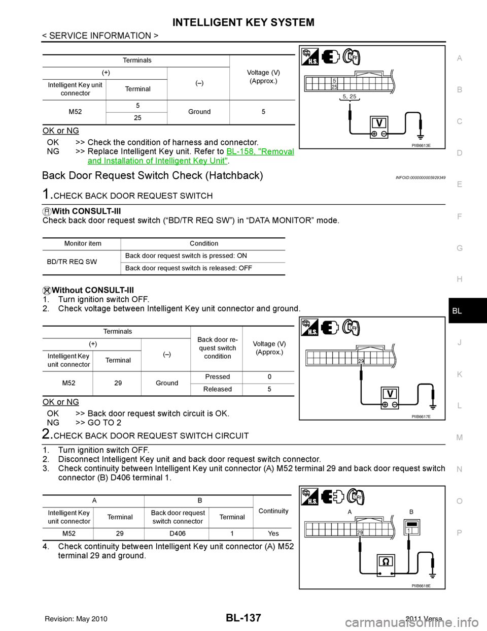
Back Door Request Switch Check (Hatchback)INFOID:0000000005929349
1.CHECK BACK DOOR REQUEST SWITCH
With CONSULT-III
Check back door request switch (“BD/TR REQ SW”) in “DATA MONITOR” mode.
Without CONSULT-III
1. Turn ignition switch OFF.
2. Check voltage between Intelligent Key unit connector and ground.
OK or NG
OK >> Back door request switch circuit is OK.
NG >> GO TO 2
2.CHECK BACK DOOR REQUEST SWITCH CIRCUIT
1. Turn ignition switch OFF.
2. Disconnect Intelligent Key unit and back door request switch connector.
3. Check continuity between Intelligent Key unit connector (A) M52 terminal 29 and back door request switch connector (B) D406 terminal 1.
4. Check continuity between Intelligent Key unit connector (A) M52 terminal 29 and ground.
Te r m i n a l s
Voltage (V)(Approx.)
(+)
(–)
Intelligent Key unit
connector Te r m i n a l
M52 5
Ground 5
25
PIIB6613E
Monitor item Condition
BD/TR REQ SW Back door request switch is pressed: ON
Back door request switch is released: OFF
Te r m i n a l s
Back door re-
quest switch condition Voltage (V)
(Approx.)
(+)
(–)
Intelligent Key
unit connector Te r m i n a l
M52 29Ground Pressed
0
Released 5
PIIB6617E
AB
Continuity
Intelligent Key
unit connector Te r m i n a l Back door request
switch connector Te r m i n a l
M52 29D406 1Yes
PIIB6618E
Revision: May 2010 2011 Versa
Page 690 of 3787

BL-180
< SERVICE INFORMATION >
BACK DOOR LOCK
1: With Intelligent Key
2: Without Intelligent Key
3: Hatchback without Intelligent Key
4: Sedan without Intelligent Key
5: Hatchback
6: Sedan
7: With power door locks
8: With power windows
Terminal and Reference Value for Intelligent Key UnitINFOID:0000000006215775
63 BR Interior room lamp Output OFFAny door
switchON (open)
0V
OFF (closed) Battery voltage
65
7SB All door lock actuators
(lock) Output OFFOFF (neutral)
0V
ON (lock) Battery voltage
66
7G Front door lock actua-
tor RH, rear door lock
actuators LH/RH (un-
lock) Output OFFOFF (neutral)
0V
ON (unlock) Battery voltage
67 B Ground Input ON—0V
68
8L Power window power
supply (RAP)
Output —Ignition switch ON
Battery voltage
Within 45 seconds after igni-
tion switch OFF Battery voltage
More than 45 seconds after ig-
nition switch OFF 0V
When front door LH or RH is
open or power window timer
operates 0V
69
8P Battery power supply OutputOFF
— Battery voltage
70 Y Battery power supply Input OFF —Battery voltage
Te r m i n a l
Wire
color Signal name Signal
input/
output Measuring condition
Reference value or waveform
(Approx.)
Ignition
switch Operation or condition
Te r m i n a lWire
Color Item Condition
Voltage (V)Approx.
Ignition
Switch
Position Operation or Conditions
1R Steering lock solenoid
power supply
LOCK
— 5
2 L CAN-H —— —
3 P CAN-L —— —
4O Intelligent Key warning
buzzer LOCKOperate door request
switch. Buzzer OFF
Battery voltage
Sound buzzer 0
5G Front door request
switch LH —Press door request switch (driver side).
0
Other than above 5
6 Y Ignition switch (ON) ON —Battery voltage
7 LG Key switch LOCKInsert mechanical key into ignition switch. Battery voltage
Remove mechanical key from ignition
switch.
0
Revision: May 2010
2011 Versa
Page 692 of 3787

BL-182
< SERVICE INFORMATION >
BACK DOOR LOCK
*1: With continuously variable transmission (CVT) or automatic transmission (A/T).
*2: With manual transmission (M/T).
CONSULT-III Function (BCM)INFOID:0000000005929384
CONSULT-III can display each diagnostic item us ing the diagnostic test modes shown following.
28 YUnlock sensor
(driver side) —Door (driver si
de) is locked. 5
Door (driver side ) is unlocked. 0
29 V Back door request
switch (hatchback)
—Press back door request switch.
0
Other than above 5
Trunk opener request
switch (sedan) —Press trunk opener request switch.
0
Other than above 5
31 BR Steering lock solenoid
ground ——
0
32 GR Steering lock solenoid
communication signal LOCKWhen Intelligent Key is inside vehicle,
press ignition knob switch.
Other than above
5
33 R Rear floor antenna (+)
signal
LOCK• Any door open
→ all door close
• Press ignition knob switch: ON (Ignition
knob switch)
34 G Rear floor antenna (-)
signal
37 BR Front outside antenna
RH (+) signal
LOCK Press door request switch RH.
38 Y Front outside antenna
RH (-) signal
Te r m i n a l
Wire
Color Item Condition
Voltage (V)Approx.
Ignition
Switch
Position Operation or Conditions
SIIA1911J
PIIB5502J
SIIA1910J
Diagnostic mode
Description
WORK SUPPORT Supports inspections and adjustments. Commands are transmitted to the BCM for setting the status
suitable for required operation, input/output signals are received from the BCM and received date
is displayed.
DATA MONITOR Displays BCM input/output data in real time. ACTIVE TEST Operation of electrical loads can be checked by sending drive signal to them.
SELF DIAGNOSTIC RESULT Displays BCM self-diagnosis results.
CAN DIAG SUPPORT MNTR The result of transmit/receive diagnosis of CAN communication can be read. ECU IDENTIFICATION BCM part number can be read.CONFIGURATION Performs BCM configuration read/write functions.
Revision: May 2010 2011 Versa