2011 NISSAN LATIO diagram
[x] Cancel search: diagramPage 2818 of 3787

GW-64
< SERVICE INFORMATION >
DOOR MIRROR
DOOR MIRROR
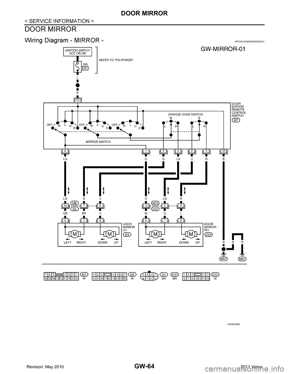
Wiring Diagram - MIRROR -INFOID:0000000005929512
LIWA0559E
Revision: May 20102011 Versa
Page 2847 of 3787

LAN-1
ELECTRICAL
C
DE
F
G H
I
J
L
M
SECTION LAN
A
B
LAN
N
O P
CONTENTS
LAN SYSTEM
CAN FUNDAMENTAL
SERVICE INFORMATION .. ..........................
6
PRECAUTIONS .............................................. .....6
Precautions for Trouble Diagnosis ...................... ......6
Precautions for Harness Repair ................................6
CAN COMMUNICATION SYSTEM ................ .....7
System Description ............................................. ......7
System Diagram ........................................................7
CAN Communication Control Circuit .........................8
DIAG ON CAN .....................................................9
Description .......................................................... ......9
System Diagram ........................................................9
TROUBLE DIAGNOSIS .....................................10
Condition of Error Detection ................................ ....10
Symptom When Error Occurs in CAN Communi-
cation System ...................................................... ....
10
CAN Diagnosis with CONSULT-III ..........................13
Self-Diagnosis .........................................................14
CAN Diagnostic Support Monitor ............................14
How to Use CAN Communication Signal Chart ......16
DIAGNOSIS AND REPAIR WORKFLOW .........17
Trouble Diagnosis Flow Chart ............................. ....17
Trouble Diagnosis Procedure ..................................17
CAN
SERVICE INFORMATION .. .........................
22
HOW TO USE THIS SECTION ....................... ....22
Caution ................................................................ ....22
Abbreviation List ......................................................22
PRECAUTIONS ..................................................23
Precaution for Supplemental Restraint System
(SRS) "AIR BAG" and "SEAT BELT PRE-TEN-
SIONER" ............................................................. ....
23
Precautions for Trouble Diagnosis ..........................23
Precautions for Harness Repair .......................... ....23
DIAGNOSIS AND REPAIR WORKFLOW ........25
Interview Sheet ........................................................25
CAN COMMUNICATION SYSTEM ...................26
CAN System Specification Chart .............................26
CAN Communication Signal Chart ..........................27
CAN COMMUNICATION SYSTEM ...................29
Component Parts Location ......................................29
Schematic ................................................................30
Wiring Diagram - CAN - ...........................................31
MALFUNCTION AREA CHART ........................33
Main Line .................................................................33
Branch Line .............................................................33
Short Circuit .............................................................33
MAIN LINE BETWEEN DLC AND ABS CIR-
CUIT ..................................................................
34
Diagnosis Procedure ...............................................34
MAIN LINE BETWEEN DLC AND TCM CIR-
CUIT ..................................................................
35
Diagnosis Procedure ...............................................35
ECM BRANCH LINE CIRCUIT .........................36
Diagnosis Procedure ...............................................36
BCM BRANCH LINE CIRCUIT .........................37
Diagnosis Procedure ...............................................37
DLC BRANCH LINE CIRCUIT ..........................38
Diagnosis Procedure ...............................................38
EPS BRANCH LINE CIRCUIT ..........................39
Diagnosis Procedure ...............................................39
I-KEY BRANCH LINE CIRCUIT ........................40
Diagnosis Procedure ...............................................40
M&A BRANCH LINE CIRCUIT .........................41
Revision: May 2010 2011 Versa
Page 2853 of 3787
![NISSAN LATIO 2011 Service Repair Manual CAN COMMUNICATION SYSTEMLAN-7
< SERVICE INFORMATION > [CAN FUNDAMENTAL]
C
D
E
F
G H
I
J
L
M A
B
LAN
N
O P
CAN COMMUNICATION SYSTEM
System DescriptionINFOID:0000000005928514
• CAN communication is a NISSAN LATIO 2011 Service Repair Manual CAN COMMUNICATION SYSTEMLAN-7
< SERVICE INFORMATION > [CAN FUNDAMENTAL]
C
D
E
F
G H
I
J
L
M A
B
LAN
N
O P
CAN COMMUNICATION SYSTEM
System DescriptionINFOID:0000000005928514
• CAN communication is a](/manual-img/5/57357/w960_57357-2852.png)
CAN COMMUNICATION SYSTEMLAN-7
< SERVICE INFORMATION > [CAN FUNDAMENTAL]
C
D
E
F
G H
I
J
L
M A
B
LAN
N
O P
CAN COMMUNICATION SYSTEM
System DescriptionINFOID:0000000005928514
• CAN communication is a multiplex communication system. This enables the system to transmit and receive
large quantities of data at high speed by connecting c ontrol units with two communication lines (CAN-H and
CAN-L).
• Control units on the CAN network transmit signals us ing the CAN communication control circuit. They
receive only necessary signals from other c ontrol units to operate various functions.
• CAN communication lines adopt twisted-pair line st yle (two lines twisted) for noise immunity.
System DiagramINFOID:0000000005928515
Each control unit passes an electric current to the termination circuits when transmitting CAN communication
signal. The termination circuits produce an electric al potential difference between CAN-H and CAN-L. CAN
communication system transmits and receives CAN communication signals by the potential difference.
SKIB8887E
Component Description
Main line CAN communication line between splices
Branch line CAN communication line between splice and a control unit
Splice A point connecting a branch line with a main line
Termination circuit Refer to LAN-8, "
CAN Communication Control Circuit".
Revision: May 2010 2011 Versa
Page 2855 of 3787
![NISSAN LATIO 2011 Service Repair Manual DIAG ON CANLAN-9
< SERVICE INFORMATION > [CAN FUNDAMENTAL]
C
D
E
F
G H
I
J
L
M A
B
LAN
N
O P
DIAG ON CAN
DescriptionINFOID:0000000005928517
“Diag on CAN” is a diagnosis using CAN communication ins NISSAN LATIO 2011 Service Repair Manual DIAG ON CANLAN-9
< SERVICE INFORMATION > [CAN FUNDAMENTAL]
C
D
E
F
G H
I
J
L
M A
B
LAN
N
O P
DIAG ON CAN
DescriptionINFOID:0000000005928517
“Diag on CAN” is a diagnosis using CAN communication ins](/manual-img/5/57357/w960_57357-2854.png)
DIAG ON CANLAN-9
< SERVICE INFORMATION > [CAN FUNDAMENTAL]
C
D
E
F
G H
I
J
L
M A
B
LAN
N
O P
DIAG ON CAN
DescriptionINFOID:0000000005928517
“Diag on CAN” is a diagnosis using CAN communication instead of previous DDL1 and DDL2 communication
lines, between control units and diagnosis unit.
System DiagramINFOID:0000000005928518
SKIB8714E
Name Harness Description
DDL1 Tx
Rx
It is used for trouble diagnosis. (CAN-H and CAN-L are used for controlling)
DDL2 K-LINE It is used for trouble diagnosis. (CAN-H and CAN-L are used for controlling)
Diag on CAN CAN-H
CAN-L It is used for trouble diagnosis and control.
Revision: May 2010
2011 Versa
Page 2877 of 3787
![NISSAN LATIO 2011 Service Repair Manual CAN COMMUNICATION SYSTEMLAN-31
< SERVICE INFORMATION > [CAN]
C
D
E
F
G H
I
J
L
M A
B
LAN
N
O P
Wiring Diagram - CAN -INFOID:0000000005928537
ABMWA0491GB
Revision: May 2010 2011 Versa NISSAN LATIO 2011 Service Repair Manual CAN COMMUNICATION SYSTEMLAN-31
< SERVICE INFORMATION > [CAN]
C
D
E
F
G H
I
J
L
M A
B
LAN
N
O P
Wiring Diagram - CAN -INFOID:0000000005928537
ABMWA0491GB
Revision: May 2010 2011 Versa](/manual-img/5/57357/w960_57357-2876.png)
CAN COMMUNICATION SYSTEMLAN-31
< SERVICE INFORMATION > [CAN]
C
D
E
F
G H
I
J
L
M A
B
LAN
N
O P
Wiring Diagram - CAN -INFOID:0000000005928537
ABMWA0491GB
Revision: May 2010 2011 Versa
Page 3033 of 3787

LT-1
ELECTRICAL
C
DE
F
G H
I
J
L
M
SECTION LT
A
B
LT
N
O P
CONTENTS
LIGHTING SYSTEM
SERVICE INFORMATION .. ..........................3
PRECAUTIONS .............................................. .....3
Precaution for Supplemental Restraint System
(SRS) "AIR BAG" and "SEAT BELT PRE-TEN-
SIONER" ............................................................. ......
3
Precaution Necessary for Steering Wheel Rota-
tion After Battery Disconnect ............................... ......
3
HEADLAMP (FOR USA) .....................................5
Component Parts and Harness Connector Loca-
tion ...................................................................... ......
5
System Description ...................................................5
CAN COMMUNICATION SYSTEM DESCRIP-
TION .................................................................... ......
6
Schematic .................................................................7
Wiring Diagram .........................................................8
Terminal and Reference Value for BCM .................11
Terminal and Reference Value for IPDM E/R .........11
How to Perform Trouble Diagnosis .........................12
Preliminary Check ...................................................12
CONSULT-III Function (BCM) .................................12
CONSULT-III Function (IPDM E/R) .........................13
Headlamp High Beam Does Not Illuminate (Both
Sides) .................................................................. ....
15
Headlamp High Beam Does Not Illuminate (One
Side) .................................................................... ....
17
High Beam Indicator Lamp Does Not Illuminate .....18
Headlamp Low Beam Does Not Illuminate (Both
Sides) .................................................................. ....
19
Headlamp Low Beam Does Not Illuminate (One
Side) .................................................................... ....
21
Headlamps Do Not Turn OFF .................................22
Aiming Adjustment ..................................................23
Bulb Replacement ...................................................24
Removal and Installation .........................................25
Disassembly and Assembly ................................ ....25
HEADLAMP (FOR CANADA) - DAYTIME
LIGHT SYSTEM - ........................................... ....
27
Component Parts and Harness Connector Loca-
tion ....................................................................... ....
27
System Description ..................................................27
CAN Communication System Description ...............29
Schematic ................................................................30
Wiring Diagram - DTRL - .........................................31
Terminal and Reference Value for BCM ..................34
Terminal and Reference Value for IPDM E/R ...... ....34
How to Perform Trouble Diagnosis ..........................35
Preliminary Check ...................................................35
CONSULT-III Function (BCM) .................................35
CONSULT-III Function (IPDM E/R) ..................... ....35
Daytime Light Control Does Not Operate Properly
(High Beam Headlamps Operate Properly) .............
35
Aiming Adjustment ...................................................37
Bulb Replacement ...................................................38
Removal and Installation .........................................39
Disassembly and Assembly .....................................39
FRONT FOG LAMP ..........................................41
Component Parts and Harness Connector Loca-
tion ...........................................................................
41
System Description ..................................................41
CAN Communication System Description ...............42
Wiring Diagram - F/FOG - .......................................43
Terminal and Reference Value for BCM ..................44
Terminal and Reference Value for IPDM E/R ...... ....44
How to Proceed with Trouble Diagnosis ..................45
Preliminary Check ............................................... ....45
CONSULT-III Function (BCM) .................................45
CONSULT-III Function (IPDM E/R) ..................... ....45
Front Fog lamps Do Not Illuminate (Both Sides) .....45
Front Fog Lamp Does Not Illuminate (One Side) ....47
Aiming Adjustment ...................................................48
Bulb Replacement ...................................................49
Removal and Installation .........................................49
TURN SIGNAL AND HAZARD WARNING
LAMPS ..............................................................
50
Component Parts and Harness Connector Loca-
tion ...........................................................................
50
Revision: May 2010 2011 Versa
Page 3034 of 3787

LT-2
System Description .................................................50
CAN Communication System Description ..............52
Schematic ............................................................ ...53
Wiring Diagram - TURN - ........................................54
Terminal and Reference Value for BCM .................57
How to Proceed with Trouble Diagnosis .................57
Preliminary Check ..................................................58
CONSULT-III Function (BCM) ................................58
Turn Signals Do Not Operate .................................58
Front Turn Signal Lamp Does Not Operate ............58
Rear Turn Signal Lamp Does Not Operate ............59
Hazard Warning Lamp Does Not Operate But
Turn Signal Lamp Operates ...................................
60
Turn Signal Indicator Lamp Does Not Operate ......61
Bulb Replacement for Front Turn Signal Lamp ......61
Bulb Replacement for Rear Turn Signal Lamp .......61
Removal and Installation of Front Turn Signal
Lamp .......................................................................
61
Removal and Installation of Rear Turn Signal
Lamp .......................................................................
61
LIGHTING AND TURN SIGNAL SWITCH .........62
Removal and Installation ..................................... ...62
HAZARD SWITCH .............................................63
Removal and Installation ..................................... ...63
COMBINATION SWITCH ..................................64
Wiring Diagram - COMBSW - .............................. ...64
Combination Switch Reading Function ...................64
Terminal and Reference Value for BCM .................65
CONSULT-III Function (BCM) ................................65
Combination Switch Inspection ..............................65
Removal and Installation ..................................... ...67
STOP LAMP ......................................................68
Wiring Diagram - STOP/L .................................... ...68
Wiring Diagram - STOP/L .......................................69
Bulb Replacement (High-Mounted Stop Lamp) ......69
Bulb Replacement (Rear Combination Lamp) ........70
Removal and Installation (High-Mounted Stop
Lamp) .....................................................................
70
Removal and Installation (Rear Combination
Lamp) .................................................................. ...
71
BACK-UP LAMP ................................................72
Wiring Diagram - BACK/L - .................................. ...72
Bulb Replacement ..................................................72
Removal and Installation ........................................73
PARKING, LICENSE PLATE AND TAIL
LAMPS ...............................................................
74
Component Parts and Harness Connector Loca-
tion ....................................................................... ...
74
System Description .................................................74
CAN Communication System Description ........... ...75
Schematic ...............................................................76
Wiring Diagram - TAIL/L - .......................................77
Terminal and Reference Value for BCM .............. ...80
Terminal and Reference Value for IPDM E/R .........80
How to Proceed with Trouble Diagnosis .................81
Preliminary Check ...................................................81
CONSULT-III Function (BCM) ............................. ...81
CONSULT-III Function (IPDM E/R) ........................81
Parking, License Plate and Tail Lamps Do Not Il-
luminate ..................................................................
81
Parking, License Plate and Tail Lamps Do Not
Turn OFF (After Approx. 10 Minutes) .....................
84
Bulb Replacement ................................................ ...84
Removal and Installation .........................................85
REAR COMBINATION LAMP ........................ ...87
Component .......................................................... ...87
Bulb Replacement ...................................................87
Removal and Installation .........................................88
Disassembly and Assembly ................................. ...88
INTERIOR LAMP ...............................................90
Map Lamp ............................................................ ...90
Luggage Room Lamp, Hatch Back .........................90
Trunk Room Lamp, Sedan ......................................91
Vanity Mirror Lamp ..................................................91
INTERIOR ROOM LAMP ...................................93
Component Parts and Harness Connector Loca-
tion ....................................................................... ...
93
System Description .................................................93
Schematic ...............................................................97
Wiring Diagram - INT/L - .........................................98
Terminal and Reference Value for BCM ...............102
How to Proceed with Trouble Diagnosis ...............102
Preliminary Check .................................................103
CONSULT-III Function (BCM) ............................. .103
Interior Room Lamp Control Does Not Operate
(With Map Lamp) ..................................................
104
Interior Room Lamp Control Does Not Operate
(Without Map Lamp) .............................................
106
Bulb Replacement .................................................107
Removal and Installation .......................................108
ILLUMINATION .............................................. ..109
System Description .............................................. .109
CAN Communication System Description ............110
Schematic .............................................................111
Wiring Diagram - ILL - ...........................................112
BULB SPECIFICATIONS ............................... ..116
Headlamp ............................................................. .116
Exterior Lamp ........................................................116
Interior Lamp/Illumination .....................................
Revision: May 2010 2011 Versa
Page 3040 of 3787

LT-8
< SERVICE INFORMATION >
HEADLAMP (FOR USA)
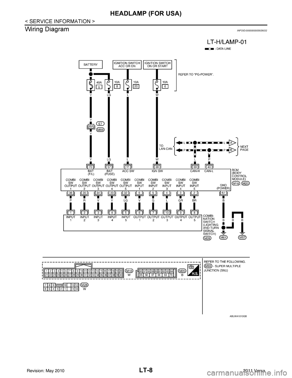
Wiring Diagram
INFOID:0000000005929032
ABLWA1013GB
Revision: May 2010 2011 Versa