2011 NISSAN LATIO engine
[x] Cancel search: enginePage 973 of 3787
![NISSAN LATIO 2011 Service Repair Manual BRC-84
< SERVICE INFORMATION >[VDC/TCS/ABS]
TROUBLE DIAGNOSES FOR SYMPTOMS
YES >> Refer to BRC-60, "CONSULT-III Function (ABS)".
NO >> Refer to DI-21, "
Schematic".
Vehicle Jerks During TCS/VDC Activ NISSAN LATIO 2011 Service Repair Manual BRC-84
< SERVICE INFORMATION >[VDC/TCS/ABS]
TROUBLE DIAGNOSES FOR SYMPTOMS
YES >> Refer to BRC-60, "CONSULT-III Function (ABS)".
NO >> Refer to DI-21, "
Schematic".
Vehicle Jerks During TCS/VDC Activ](/manual-img/5/57357/w960_57357-972.png)
BRC-84
< SERVICE INFORMATION >[VDC/TCS/ABS]
TROUBLE DIAGNOSES FOR SYMPTOMS
YES >> Refer to BRC-60, "CONSULT-III Function (ABS)".
NO >> Refer to DI-21, "
Schematic".
Vehicle Jerks During TCS/VDC ActivationINFOID:0000000005928505
1.ABS ACTUATOR AND ELECTRIC UNIT (CONTROL UNIT) SELF-DIAGNOSIS
Perform ABS actuator and electric unit (control unit) self-diagnosis.
Are self-diagnosis result items displayed?
YES >> After checking and repairing the applicable item , perform the ABS actuator and electric unit (con-
trol unit) self-diagnosis again.
NO >> GO TO 2.
2.ENGINE SPEED SIGNAL INSPECTION
Perform data monitor with CONSULT-III for the ABS actuator and electric unit (control unit).
Is the engine speed at idle 400 rpm or higher?
YES >> GO TO 4.
NO >> GO TO 3.
3.ECM SELF-DIAGNOSIS
Perform ECM self-diagnosis.
Are self-diagnosis result items displayed?
YES >> After checking and repairing the applicable item, perform the ECM self-diagnosis again.
NO >> GO TO 4.
4.TCM SELF-DIAGNOSIS
Perform TCM self-diagnosis.
Are self-diagnosis result items displayed?
YES >> After checking and repairing the applicable item, perform the TCM self-diagnosis again.
NO >> GO TO 5.
5.CONNECTOR INSPECTION
Disconnect the ABS actuator and electric unit (contro l unit) connector and the ECM connectors and check the
terminals for deformation, disconnection, looseness or damage.
OK or NG
OK >> GO TO 6.
NG >> Repair or replace the connector terminal.
6.CAN COMMUNICATION INSPECTION
Check the CAN communication system. Refer to BRC-79, "
CAN Communication System Inspection".
OK or NG
OK >> Inspection End.
NG >> Reconnect the connectors, and per form ABS actuator and electric unit (control unit) self-diagno-
sis.
Revision: May 2010 2011 Versa
Page 974 of 3787
![NISSAN LATIO 2011 Service Repair Manual ON-VEHICLE SERVICEBRC-85
< SERVICE INFORMATION > [VDC/TCS/ABS]
C
D
E
G H
I
J
K L
M A
B
BRC
N
O P
ON-VEHICLE SERVICE
Adjustment of Steering Angle Sensor Neutral PositionINFOID:0000000005928506
After re NISSAN LATIO 2011 Service Repair Manual ON-VEHICLE SERVICEBRC-85
< SERVICE INFORMATION > [VDC/TCS/ABS]
C
D
E
G H
I
J
K L
M A
B
BRC
N
O P
ON-VEHICLE SERVICE
Adjustment of Steering Angle Sensor Neutral PositionINFOID:0000000005928506
After re](/manual-img/5/57357/w960_57357-973.png)
ON-VEHICLE SERVICEBRC-85
< SERVICE INFORMATION > [VDC/TCS/ABS]
C
D
E
G H
I
J
K L
M A
B
BRC
N
O P
ON-VEHICLE SERVICE
Adjustment of Steering Angle Sensor Neutral PositionINFOID:0000000005928506
After removing/installing or replacing ABS actuator and electric unit (control unit), steering angle sensor, steer-
ing and suspension components which affect wheel alignment or after adjusting wheel alignment, be sure to
adjust neutral position of steering angle sensor before running vehicle.
NOTE:
Adjustment of steering angle sensor neutral position requires CONSULT-III.
1. Stop vehicle with front wheels in straight-ahead position.
2. Connect CONSULT-III to data link connector on vehicle, and turn ignition switch ON (do not start engine).
3. Touch “ABS”, “WORK SUPPORT” and “ST ANGLE SENSOR ADJUSTMENT” on CONSULT-III screen in
this order.
4. Touch “START”. CAUTION:
Do not touch steering wheel whil e adjusting steering angle sensor.
5. After approximately 10 seconds, touch “END”. (After approximately 60 seconds, it ends automatically.)
6. Turn ignition switch OFF, then turn it ON again.
7. Run vehicle with front wheels in straight-ahead position, then stop.
8. Select “DATA MONITOR”, “SELECTION FROM MENU”, and “STR ANGLE SIG” on CONSULT-III screen.
Then check that “STR ANGLE SIG” is within 0 ±2.5 deg. If value is more than specification, repeat steps 1
to 5.
9. Erase memory of ABS actuator and electric unit (control unit) and ECM.
10. Turn ignition switch to OFF.
Revision: May 2010 2011 Versa
Page 978 of 3787
![NISSAN LATIO 2011 Service Repair Manual ACTUATOR AND ELECTRIC UNIT (ASSEMBLY)BRC-89
< SERVICE INFORMATION > [VDC/TCS/ABS]
C
D
E
G H
I
J
K L
M A
B
BRC
N
O P
ACTUATOR AND ELECTRIC UNIT (ASSEMBLY)
Removal and InstallationINFOID:000000000592850 NISSAN LATIO 2011 Service Repair Manual ACTUATOR AND ELECTRIC UNIT (ASSEMBLY)BRC-89
< SERVICE INFORMATION > [VDC/TCS/ABS]
C
D
E
G H
I
J
K L
M A
B
BRC
N
O P
ACTUATOR AND ELECTRIC UNIT (ASSEMBLY)
Removal and InstallationINFOID:000000000592850](/manual-img/5/57357/w960_57357-977.png)
ACTUATOR AND ELECTRIC UNIT (ASSEMBLY)BRC-89
< SERVICE INFORMATION > [VDC/TCS/ABS]
C
D
E
G H
I
J
K L
M A
B
BRC
N
O P
ACTUATOR AND ELECTRIC UNIT (ASSEMBLY)
Removal and InstallationINFOID:0000000005928509
CAUTION:
• Before servicing, disconnect battery negative terminal.
• To remove brake tube, use flare nut wrench to pr event flare nuts and brake tube from being dam-
aged. To install, use flare nut torque wrench, ti ghten flare nut to the specified torque. Refer to BR-11,
"Hydraulic Circuit".
• Do not apply excessive impact to ABS actuator and elect ric unit (control unit), such as dropping it.
• Do not remove and install actuator by holding harness.
• After work is completed, bleed the air from the brake hydraulic system. Refer to BR-9, "
Bleeding
Brake System".
REMOVAL
1. Disconnect the battery negative terminal.
2. Remove the cowl top. Refer to EI-24, "
Removal and Installation".
3. Disconnect ABS actuator and electric unit (control unit) connector.
4. Loosen brake tube flare nuts, then remove brake tubes from ABS actuator and electric unit (control unit).
5. Remove brake booster hose from engine. Refer to BR-23, "
Removal and Installation".
6. Remove ABS actuator and electric unit (control unit) bracket bolts.
7. Remove ABS actuator and electric unit (control unit).
1. To front right caliper 2. To rear left wheel cylinder 3. To rear right wheel cylinder
4. To front left caliper 5. From master cylinder primary side 6. From master cylinder secondary side
7. ABS actuator and electric unit (control unit) 8. Harness connector
Front
AWFIA0532GB
Revision: May 2010 2011 Versa
Page 983 of 3787

CL-2
< SERVICE INFORMATION >
PRECAUTIONS
SERVICE INFORMATION
PRECAUTIONS
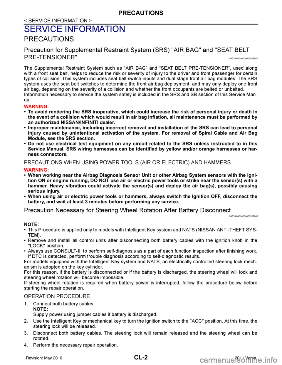
Precaution for Supplemental Restraint System (SRS) "AIR BAG" and "SEAT BELT
PRE-TENSIONER"
INFOID:0000000005928987
The Supplemental Restraint System such as “A IR BAG” and “SEAT BELT PRE-TENSIONER”, used along
with a front seat belt, helps to reduce the risk or severity of injury to the driver and front passenger for certain
types of collision. This system includes seat belt switch inputs and dual stage front air bag modules. The SRS
system uses the seat belt switches to determine the front air bag deployment, and may only deploy one front
air bag, depending on the severity of a collision and w hether the front occupants are belted or unbelted.
Information necessary to service the system safely is included in the SRS and SB section of this Service Man-
ual.
WARNING:
• To avoid rendering the SRS inopera tive, which could increase the risk of personal injury or death in
the event of a collision which would result in air bag inflation, all maintenance must be performed by
an authorized NISSAN/INFINITI dealer.
• Improper maintenance, including incorrect removal and installation of the SRS can lead to personal
injury caused by unintent ional activation of the system. For re moval of Spiral Cable and Air Bag
Module, see the SRS section.
• Do not use electrical test equipmen t on any circuit related to the SRS unless instructed to in this
Service Manual. SRS wiring harn esses can be identified by yellow and/or orange harnesses or har-
ness connectors.
PRECAUTIONS WHEN USING POWER TOOLS (AIR OR ELECTRIC) AND HAMMERS
WARNING:
• When working near the Airbag Diagnosis Sensor Unit or other Airbag System sensors with the Igni-
tion ON or engine running, DO NOT use air or electri c power tools or strike near the sensor(s) with a
hammer. Heavy vibration could activate the sensor( s) and deploy the air bag(s), possibly causing
serious injury.
• When using air or electric power tools or hammers , always switch the Ignition OFF, disconnect the
battery, and wait at least 3 minu tes before performing any service.
Precaution Necessary for Steering W heel Rotation After Battery Disconnect
INFOID:0000000005928988
NOTE:
• This Procedure is applied only to models with Intelligent Key system and NATS (NISSAN ANTI-THEFT SYS-
TEM).
• Remove and install all control units after disconnecting both battery cables with the ignition knob in the
″LOCK ″ position.
• Always use CONSULT-III to perform self-diagnosis as a part of each function inspection after finishing work.
If DTC is detected, perform trouble diagnosis according to self-diagnostic results.
For models equipped with the Intelligent Key system and NATS, an electrically controlled steering lock mech-
anism is adopted on the key cylinder.
For this reason, if the battery is disconnected or if the battery is discharged, the steering wheel will lock and
steering wheel rotation will become impossible.
If steering wheel rotation is required when battery pow er is interrupted, follow the procedure below before
starting the repair operation.
OPERATION PROCEDURE
1. Connect both battery cables. NOTE:
Supply power using jumper cables if battery is discharged.
2. Use the Intelligent Key or mechanical key to turn the ignition switch to the ″ACC ″ position. At this time, the
steering lock will be released.
3. Disconnect both battery cables. The steering lock will remain released and the steering wheel can be rotated.
4. Perform the necessary repair operation.
Revision: May 2010 2011 Versa
Page 986 of 3787

NOISE, VIBRATION AND HARSHNESS (NVH) TROUBLESHOOTINGCL-5
< SERVICE INFORMATION >
DE
F
G H
I
J
K L
M A
B
CL
N
O P
NOISE, VIBRATION AND HARSHN ESS (NVH) TROUBLESHOOTING
NVH Troubleshooting ChartINFOID:0000000005928993
Use the chart below to help you find the cause of the symptom. The numbers indicate the order of the inspec-
tion. If necessary, repair or replace these parts.
Reference pageCL-6CL-9EM-197CL-13CL-16EM-219
SUSPECTED PARTS (Possible cause)
CLUTCH PEDAL (Inspection and adjustment)
CLUTCH LINE (Air in line)
ENGINE MOUNTING (Loose)
CSC (Concentric slave cylinder) (Worn, dirty or damaged)
CLUTCH DISC (Out of true)
CLUTCH DISC (Runou t is excessive)
CLUTCH DISC (Lining broken)
CLUTCH DISC (Dirty or burned)
CLUTCH DISC (Oily)
CLUTCH DISC (Worn out)
CLUTCH DISC (Hardened)
CLUTCH DISC (Lack of spline grease)
DIAPHRAGM SPRING (Damaged)
DIAPHRAGM SPRING (Out of tip alignment)
PRESSURE PLATE (Distortion)
FLYWHEEL (Distortion)
Symptom Clutch grabs/chatters
122 2 2 2
Clutch pedal spongy 1
Clutch noisy 1
Clutch slips 1 2 23 4 5
Clutch does not disengage 12 55555 5667
Revision: May 2010 2011 Versa
Page 994 of 3787

CSC (CONCENTRIC SLAVE CYLINDER)CL-13
< SERVICE INFORMATION >
DE
F
G H
I
J
K L
M A
B
CL
N
O P
CSC (CONCENTRIC SLAVE CYLINDER)
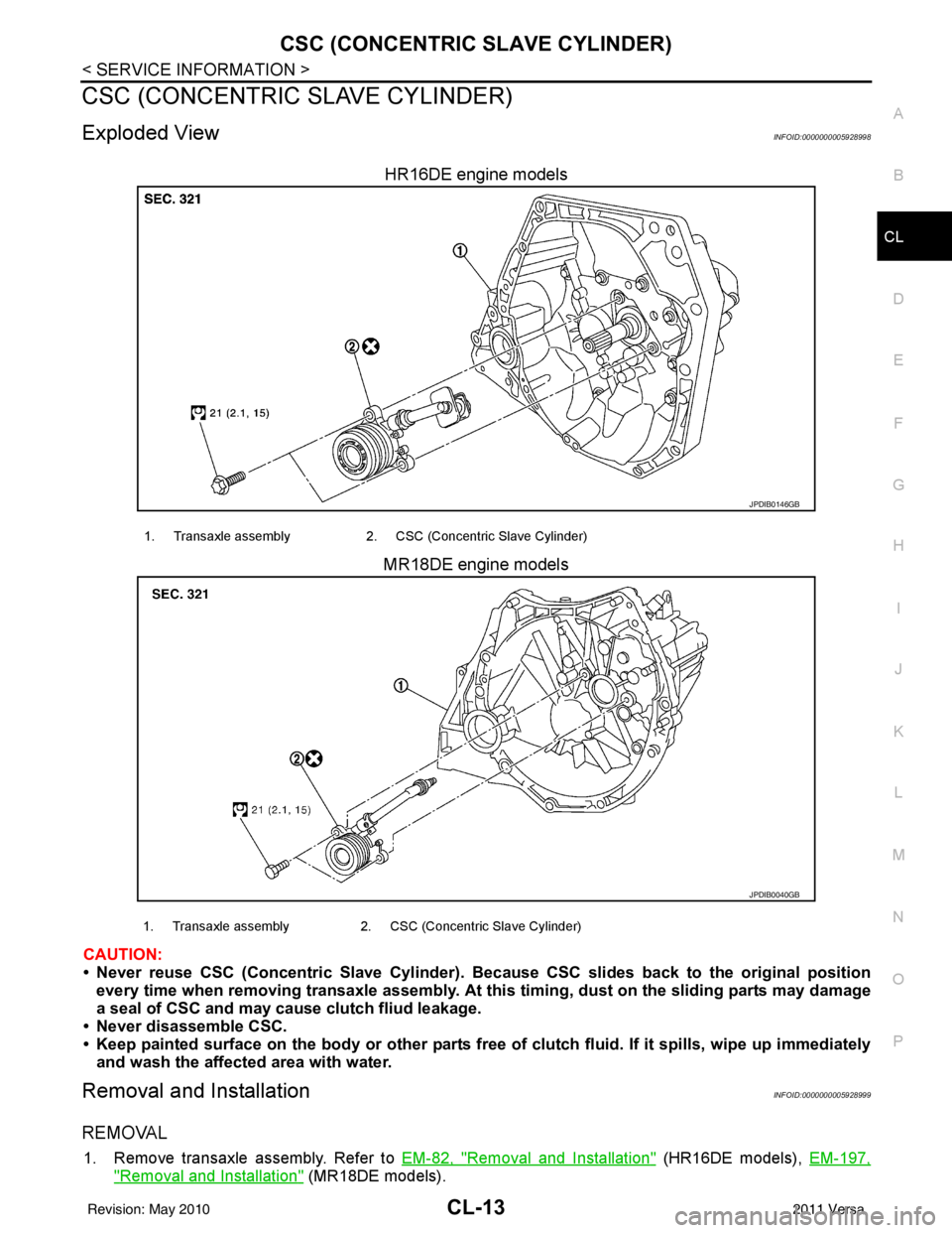
Exploded ViewINFOID:0000000005928998
HR16DE engine models
MR18DE engine models
CAUTION:
• Never reuse CSC (Concentric Slave Cylinder). Because CSC slides back to the original position every time when removing transaxle assembly. At th is timing, dust on the sliding parts may damage
a seal of CSC and may cau se clutch fliud leakage.
• Never disassemble CSC.
• Keep painted surface on the body or other parts free of clutch fluid. If it sp ills, wipe up immediately
and wash the affected area with water.
Removal and InstallationINFOID:0000000005928999
REMOVAL
1. Remove transaxle assembly. Refer to EM-82, "Removal and Installation" (HR16DE models), EM-197,
"Removal and Installation" (MR18DE models).
JPDIB0146GB
1. Transaxle assembly 2. CSC (Concentric Slave Cylinder)
JPDIB0040GB
1. Transaxle assembly2. CSC (Concentric Slave Cylinder)
Revision: May 2010 2011 Versa
Page 997 of 3787

CL-16
< SERVICE INFORMATION >
CLUTCH DISC, CLUTCH COVER AND FLYWHEEL
CLUTCH DISC, CLUTCH COVER AND FLYWHEEL
Removal and InstallationINFOID:0000000005929001
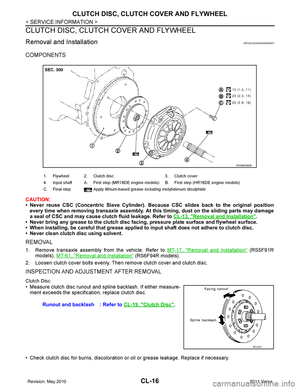
COMPONENTS
CAUTION:
• Never reuse CSC (Concentric Slave Cylinder). Because CSC slides back to the original position
every time when removing transaxle assembly. At this timing, dust on the sliding parts may damage
a seal of CSC and may cause clutch fluid leakage. Refer to CL-13, "
Removal and Installation".
• Never bring any grease to the clutch disc faci ng, pressure plate surface and flywheel surface.
• When installing, be careful that grease applied to input shaft does not adhere to clutch disc.
• Never clean clutch disc using solvent.
REMOVAL
1. Remove transaxle assembly from the vehicle. Refer to MT-17, "Removal and Installation" (RS5F91R
models), MT-61, "
Removal and Installation" (RS6F94R models).
2. Loosen clutch cover bolts evenly. Then remove clutch cover and clutch disc.
INSPECTION AND ADJUSTMENT AFTER REMOVAL
Clutch Disc
• Measure clutch disc runout and spline backlash. If either measure- ment exceeds the specificat ion, replace clutch disc.
• Check clutch disc for burns, discoloration or oil or grease leakage. Replace if necessary.
1. Flywheel 2. Clutch disc 3. Clutch cover
4. Input shaft A. First step (MR18DE engine models) B. First step (HR16DE engine models)
C. Final step Apply lithium-based grease including molybdenum disulphide
JPDIB0038GB
Runout and backlash : Refer to CL-19, "Clutch Disc".
SCL221
Revision: May 2010 2011 Versa
Page 1000 of 3787

SERVICE DATA AND SPECIFICATIONS (SDS)CL-19
< SERVICE INFORMATION >
DE
F
G H
I
J
K L
M A
B
CL
N
O P
SERVICE DATA AND SPECIFICATIONS (SDS)
Clutch Control SystemINFOID:0000000005929002
Clutch PedalINFOID:0000000005929003
Clutch DiscINFOID:0000000005929004
Clutch CoverINFOID:0000000005929005
Type of clutch control Hydraulic
Clearance between clutch pedal and ASCD switch threaded end
while clutch pedal is fully released (if equipped). 0.74 - 1.96 mm (0.0291 - 0.0772 in)
Clearance between clutch pedal and clutch interlock switch
threaded end while clutch pedal is fully depressed. 0.74 - 1.96 mm (0.0291 - 0.0772 in)
Engine type
HR16DEMR18DE
Model 200225
Facing size (outer dia. × inner dia. × thickness) 200 mm x 140 mm x 3.1 mm (7.87 in x
5.51 in x 0.122 in) 225 mm ×
160 mm × 3.2 mm (8.86 in ×
6.30 in × 0.126 in)
Thickness of disc assembly with load 7.1 - 7.5 mm (0.280 - 0.295 in) with 4,658
N (475 kg, 1,047 lb) 7.2 - 7.6 mm (0.283 - 0.299 in) with
5,394 N (550 kg, 1,213 lb)
Runout limit/diameter of the area to be measured 1.0 mm (0.039 in) / 190 mm (7.48 in) dia 1.0 mm (0.039 in) / 215 mm (8.46 in)
dia.
Maximum spline backlash (at outer edge of disc) 0.8 mm (0.031 in)0.9 mm (0.035 in)
Wear limit of facing (depth to the rivet head) 0.3 mm (0.012 in)0.3 mm (0.012 in)
Engine type HR16DEMR18DE
Set-load 4,658 N (475.1 kg, 1,047.1 lb) 5,394 N (550 kg, 1,213 lb)
Diaphragm spring lever height 29 - 31 mm (1.14 - 1.22 in)20 - 22 mm (0.79 - 0.87 in)
Uneven limit of diaphragm spring toe height 0.7 mm (0.028 in) or less0.7 mm (0.028 in) or less
Revision: May 2010 2011 Versa