2011 NISSAN LATIO engine
[x] Cancel search: enginePage 849 of 3787

BR-2
< SERVICE INFORMATION >
PRECAUTIONS
SERVICE INFORMATION
PRECAUTIONS
Precaution for Supplemental Restraint System (SRS) "AIR BAG" and "SEAT BELT
PRE-TENSIONER"
INFOID:0000000005928385
The Supplemental Restraint System such as “A IR BAG” and “SEAT BELT PRE-TENSIONER”, used along
with a front seat belt, helps to reduce the risk or severity of injury to the driver and front passenger for certain
types of collision. This system includes seat belt switch inputs and dual stage front air bag modules. The SRS
system uses the seat belt switches to determine the front air bag deployment, and may only deploy one front
air bag, depending on the severity of a collision and w hether the front occupants are belted or unbelted.
Information necessary to service the system safely is included in the SRS and SB section of this Service Man-
ual.
WARNING:
• To avoid rendering the SRS inopera tive, which could increase the risk of personal injury or death in
the event of a collision which would result in air bag inflation, all maintenance must be performed by
an authorized NISSAN/INFINITI dealer.
• Improper maintenance, including incorrect removal and installation of the SRS can lead to personal
injury caused by unintent ional activation of the system. For re moval of Spiral Cable and Air Bag
Module, see the SRS section.
• Do not use electrical test equipmen t on any circuit related to the SRS unless instructed to in this
Service Manual. SRS wiring harn esses can be identified by yellow and/or orange harnesses or har-
ness connectors.
PRECAUTIONS WHEN USING POWER TOOLS (AIR OR ELECTRIC) AND HAMMERS
WARNING:
• When working near the Airbag Diagnosis Sensor Unit or other Airbag System sensors with the Igni-
tion ON or engine running, DO NOT use air or electri c power tools or strike near the sensor(s) with a
hammer. Heavy vibration could activate the sensor( s) and deploy the air bag(s), possibly causing
serious injury.
• When using air or electric power tools or hammers , always switch the Ignition OFF, disconnect the
battery, and wait at least 3 minu tes before performing any service.
Precaution Necessary for Steering W heel Rotation After Battery Disconnect
INFOID:0000000005928386
NOTE:
• This Procedure is applied only to models with Intelligent Key system and NATS (NISSAN ANTI-THEFT SYS-
TEM).
• Remove and install all control units after disconnecting both battery cables with the ignition knob in the
″LOCK ″ position.
• Always use CONSULT-III to perform self-diagnosis as a part of each function inspection after finishing work.
If DTC is detected, perform trouble diagnosis according to self-diagnostic results.
For models equipped with the Intelligent Key system and NATS, an electrically controlled steering lock mech-
anism is adopted on the key cylinder.
For this reason, if the battery is disconnected or if the battery is discharged, the steering wheel will lock and
steering wheel rotation will become impossible.
If steering wheel rotation is required when battery pow er is interrupted, follow the procedure below before
starting the repair operation.
OPERATION PROCEDURE
1. Connect both battery cables. NOTE:
Supply power using jumper cables if battery is discharged.
2. Use the Intelligent Key or mechanical key to turn the ignition switch to the ″ACC ″ position. At this time, the
steering lock will be released.
3. Disconnect both battery cables. The steering lock will remain released and the steering wheel can be rotated.
4. Perform the necessary repair operation.
Revision: May 2010 2011 Versa
Page 854 of 3787
BRAKE PEDALBR-7
< SERVICE INFORMATION >
C
DE
G H
I
J
K L
M A
B
BR
N
O P
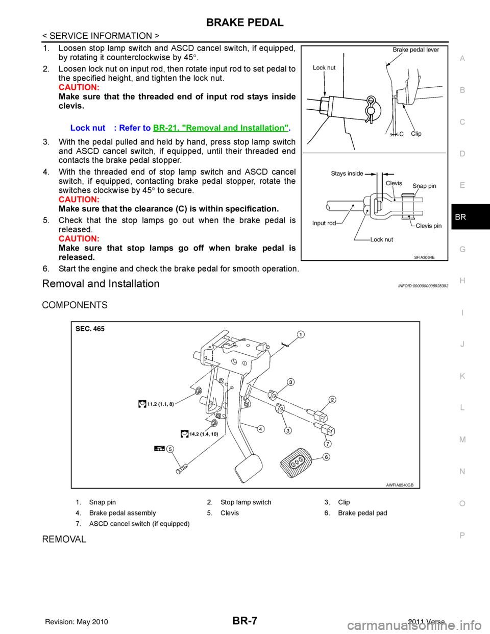
1. Loosen stop lamp switch and ASCD cancel switch, if equipped, by rotating it counterclockwise by 45 °.
2. Loosen lock nut on input rod, then rotate input rod to set pedal to the specified height, and tighten the lock nut.
CAUTION:
Make sure that the threaded end of input rod stays inside
clevis.
3. With the pedal pulled and held by hand, press stop lamp switch and ASCD cancel switch, if equipped, until their threaded end
contacts the brake pedal stopper.
4. With the threaded end of stop lamp switch and ASCD cancel switch, if equipped, contacting brake pedal stopper, rotate the
switches clockwise by 45 ° to secure.
CAUTION:
Make sure that the clearance (C) is within specification.
5. Check that the stop lamps go out when the brake pedal is released.
CAUTION:
Make sure that stop lamps go off when brake pedal is
released.
6. Start the engine and check the brake pedal for smooth operation.
Removal and InstallationINFOID:0000000005928392
COMPONENTS
REMOVAL
Lock nut : Refer to BR-21, "Removal and Installation".
SFIA3064E
1. Snap pin 2. Stop lamp switch3. Clip
4. Brake pedal assembly 5. Clevis6. Brake pedal pad
7. ASCD cancel switch (if equipped)
AWFIA0540GB
Revision: May 2010 2011 Versa
Page 860 of 3787
BRAKE TUBE AND HOSEBR-13
< SERVICE INFORMATION >
C
DE
G H
I
J
K L
M A
B
BR
N
O P
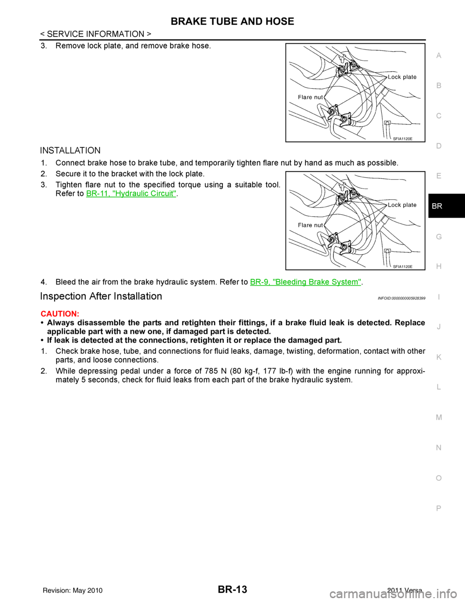
3. Remove lock plate, and remove brake hose.
INSTALLATION
1. Connect brake hose to brake tube, and temporaril y tighten flare nut by hand as much as possible.
2. Secure it to the bracket with the lock plate.
3. Tighten flare nut to the specified torque using a suitable tool. Refer to BR-11, "
Hydraulic Circuit".
4. Bleed the air from the brake hydraulic system. Refer to BR-9, "
Bleeding Brake System".
Inspection After InstallationINFOID:0000000005928399
CAUTION:
• Always disassemble the parts and retighten their fitti ngs, if a brake fluid leak is detected. Replace
applicable part with a new one, if damaged part is detected.
• If leak is detected at the connections, retighten it or replace the damaged part.
1. Check brake hose, tube, and connections for fluid leak s, damage, twisting, deformation, contact with other
parts, and loose connections.
2. While depressing pedal under a force of 785 N (80 kg-f, 177 lb-f) with the engine running for approxi- mately 5 seconds, check for fluid leaks from each part of the brake hydraulic system.
SFIA1120E
SFIA1120E
Revision: May 2010 2011 Versa
Page 867 of 3787
BR-20
< SERVICE INFORMATION >
BRAKE BOOSTER
BRAKE BOOSTER
On Board InspectionINFOID:0000000005928405
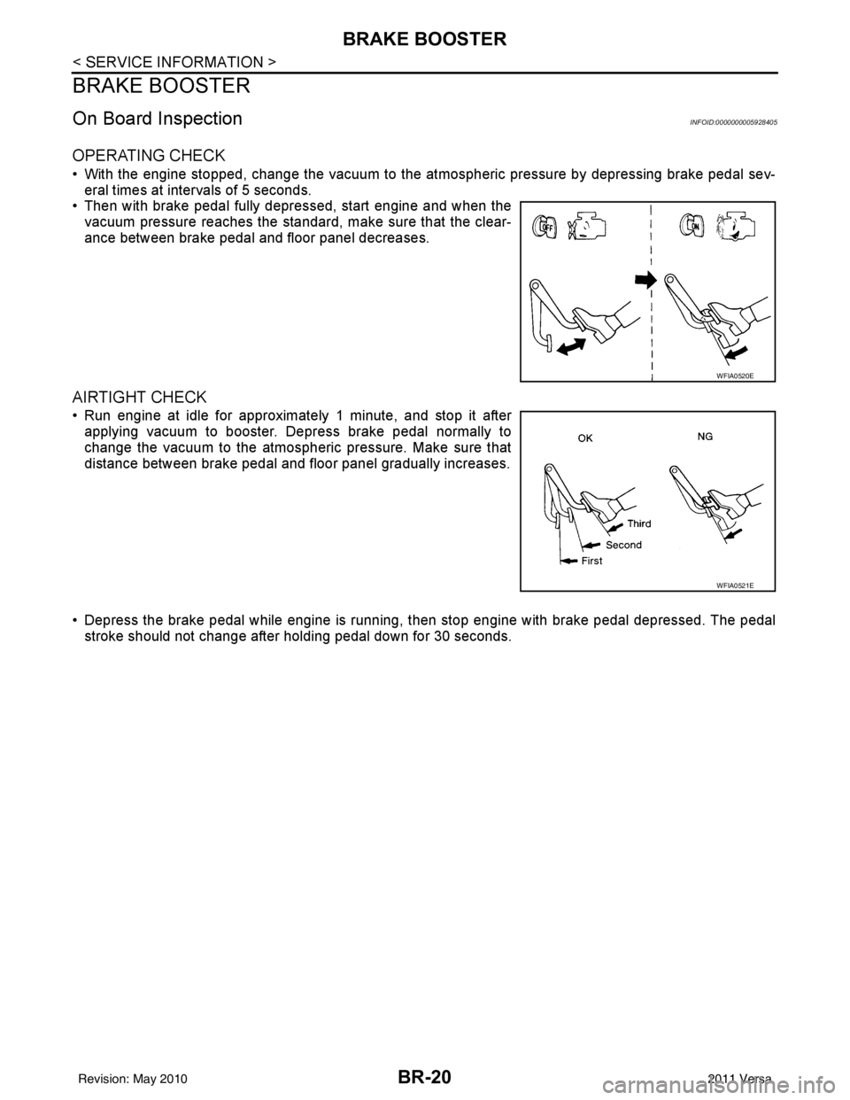
OPERATING CHECK
• With the engine stopped, change the vacuum to the atmospheric pressure by depressing brake pedal sev-
eral times at intervals of 5 seconds.
• Then with brake pedal fully depressed, start engine and when the vacuum pressure reaches the standard, make sure that the clear-
ance between brake pedal and floor panel decreases.
AIRTIGHT CHECK
• Run engine at idle for approximately 1 minute, and stop it afterapplying vacuum to booster. Depress brake pedal normally to
change the vacuum to the atmospheric pressure. Make sure that
distance between brake pedal and floor panel gradually increases.
• Depress the brake pedal while engine is running, then stop engine with brake pedal depressed. The pedal
stroke should not change after holding pedal down for 30 seconds.
WFIA0520E
WFIA0521E
Revision: May 2010 2011 Versa
Page 870 of 3787
VACUUM LINESBR-23
< SERVICE INFORMATION >
C
DE
G H
I
J
K L
M A
B
BR
N
O P
VACUUM LINES
ComponentINFOID:0000000005928407
Removal and InstallationINFOID:0000000005928408
REMOVAL
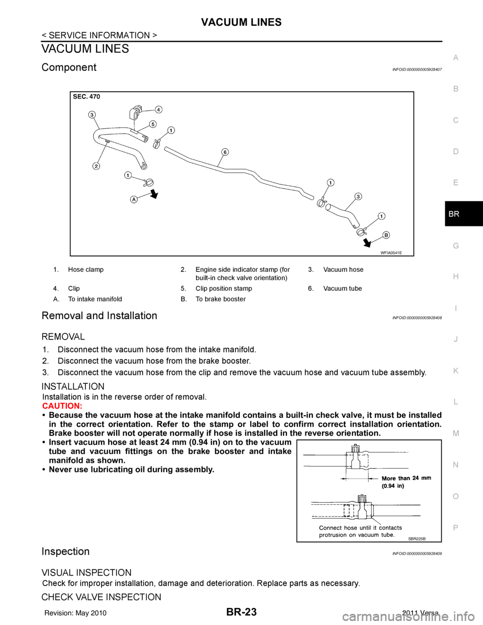
1. Disconnect the vacuum hose from the intake manifold.
2. Disconnect the vacuum hose from the brake booster.
3. Disconnect the vacuum hose from the clip and re move the vacuum hose and vacuum tube assembly.
INSTALLATION
Installation is in the reverse order of removal.
CAUTION:
• Because the vacuum hose at the intake manifold contains a built-in check valve, it must be installed
in the correct orientation. Refer to the stamp or label to confirm correct installation orientation.
Brake booster will not operate normally if ho se is installed in the reverse orientation.
• Insert vacuum hose at least 24 mm (0.94 in) on to the vacuum tube and vacuum fittings on the brake booster and intake
manifold as shown.
• Never use lubricating oil during assembly.
InspectionINFOID:0000000005928409
VISUAL INSPECTION
Check for improper installation, damage and deterioration. Replace parts as necessary.
CHECK VALVE INSPECTION
1. Hose clamp 2. Engine side indicator stamp (for
built-in check valve orientation) 3. Vacuum hose
4. Clip 5. Clip position stamp6. Vacuum tube
A. To intake manifold B. To brake booster
WFIA0541E
SBR225B
Revision: May 2010 2011 Versa
Page 871 of 3787
BR-24
< SERVICE INFORMATION >
VACUUM LINES
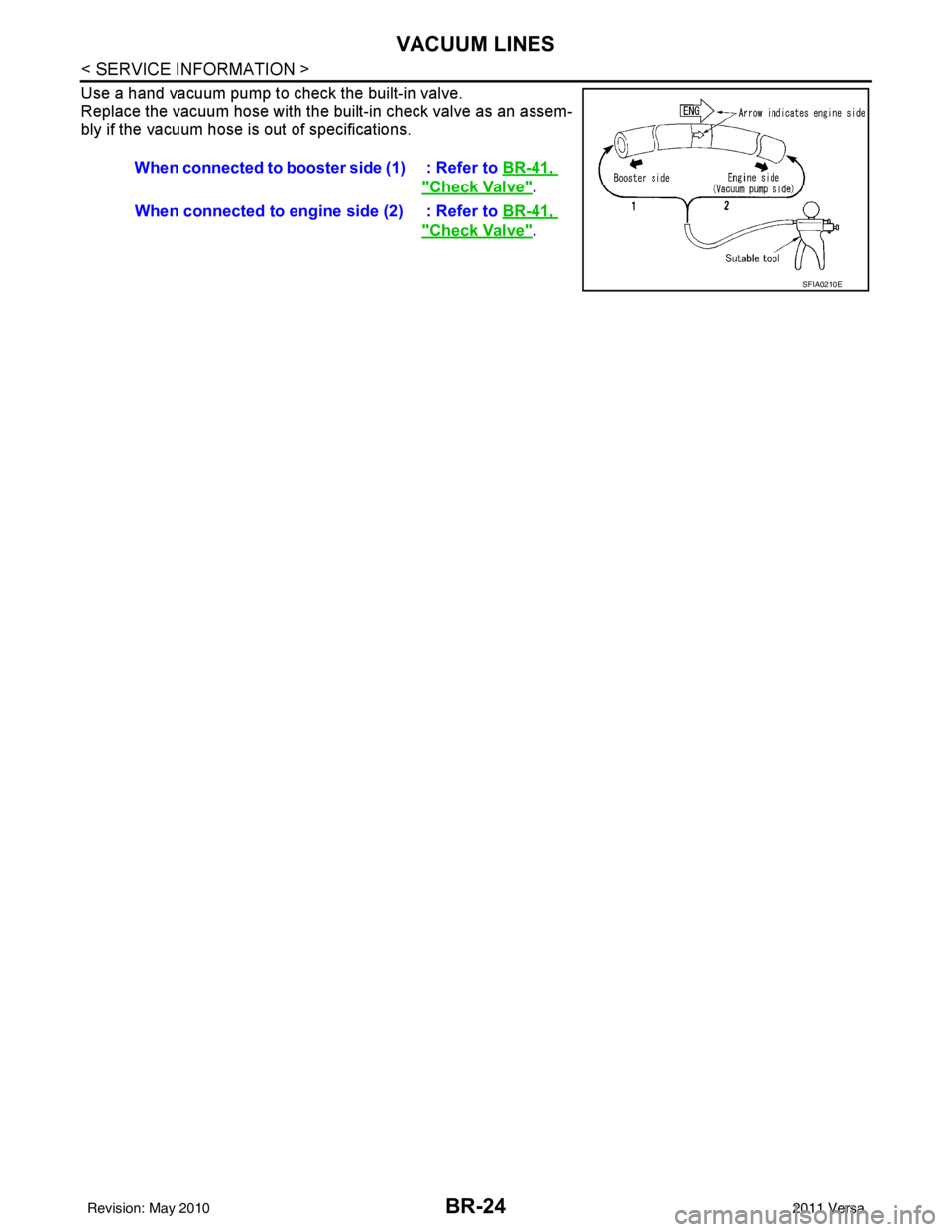
Use a hand vacuum pump to check the built-in valve.
Replace the vacuum hose with the built-in check valve as an assem-
bly if the vacuum hose is out of specifications.When connected to booster side (1) : Refer to BR-41,
"Check Valve".
When connected to engine side (2) : Refer to BR-41,
"Check Valve".
SFIA0210E
Revision: May 2010 2011 Versa
Page 888 of 3787
SERVICE DATA AND SPECIFICATIONS (SDS)BR-41
< SERVICE INFORMATION >
C
DE
G H
I
J
K L
M A
B
BR
N
O P
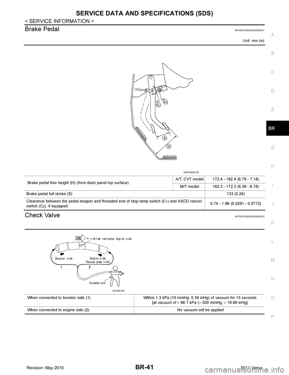
Brake PedalINFOID:0000000005928421
Unit: mm (in)
Check ValveINFOID:0000000005928422
Brake pedal free height (H) (from dash panel top surface) A/T, CVT model 172.4 - 182.4 (6.79 - 7.18)
M/T model 162.3 - 172.3 (6.39 - 6.78)
Brake pedal full stroke (S) 133 (5.24)
Clearance between the pedal stopper and threaded end of stop lamp switch (C
1) and ASCD cancel
switch (C
2), if equipped 0.74 - 1.96 (0.0291 - 0.0772)
AWFIA0557ZZ
When connected to booster side (1)
Within 1.3 kPa (10 mmHg, 0.39 inHg) of vacuum for 15 seconds
[at vacuum of – 66.7 kPa (– 500 mmHg, – 19.69 inHg]
When connected to engine side (2) No vacuum will be applied
SFIA0210E
Revision: May 2010 2011 Versa
Page 891 of 3787

BRC-2
System Component ................................................42
ABS Function ....................................... ...................42
EBD Function ...................................................... ...42
TCS Function ..........................................................43
VDC Function .........................................................43
Wheel Sensors .......................................................43
Fail-Safe Function ..................................................43
Hydraulic Circuit Diagram .......................................44
CAN COMMUNICATION ...................................45
System Description .................................................45
TROUBLE DIAGNOSIS .....................................46
How to Perform Trouble Diagnosis for Quick and
Accurate Repair ................................................... ...
46
Component Parts and Harness Connector Loca-
tion ..........................................................................
49
Schematic ...............................................................51
Wiring Diagram - VDC - ..........................................52
Basic Inspection .....................................................56
Warning Lamp and Indicator Timing .......................57
Control Unit Input/Output Signal Standard .............57
CONSULT-III Function (ABS) .................................60
TROUBLE DIAGNOSIS FOR SELF-DIAG-
NOSTIC ITEMS ............................................... ...
67
Wheel Sensor System Inspection ...........................67
Engine System Inspection ................................... ...68
ABS/TCS/VDC Control Unit Inspection ..................68
Steering Angle Sensor System Inspection .......... ...69
Yaw Rate/Side/Decel G Sensor System Inspec-
tion ....................................................................... ...
70
Solenoid and VDC Change-Over Valve System
Inspection ...............................................................
72
Actuator Motor, Motor Relay, and Circuit Inspec-
tion ....................................................................... ...
73
Stop Lamp Switch System Inspection ....................74
ABS/TCS/VDC Control Unit Power and Ground
Systems Inspection .............................................. ...
75
Brake Fluid Level Switch System Inspection ..........76
Pressure Sensor System Inspection .......................77
Transmission Range Switch System Inspection .. ...78
CAN Communication System Inspection ................79
Component Inspection ............................................79
TROUBLE DIAGNOSES FOR SYMPTOMS .....81
ABS Works Frequently ............................................81
Unexpected Pedal Action ..................................... ...81
Long Stopping Distance ..........................................82
ABS Does Not Work ...............................................82
Pedal Vibration or ABS Op eration Noise ................82
ABS Warning Lamp Does Not Come On When Ig-
nition Switch Is Turned On ................................... ...
83
ABS Warning Lamp Stays On When Ignition
Switch Is Turned On ............................................ ...
83
Vehicle Jerks During TCS/VDC Activation ..............84
ON-VEHICLE SERVICE ....................................85
Adjustment of Steering Angle Sensor Neutral Po-
sition ..................................................................... ...
85
WHEEL SENSORS ............................................86
Removal and Installation .........................................86
SENSOR ROTOR ........................................... ...88
Removal and Installation .........................................88
ACTUATOR AND ELECTRIC UNIT (ASSEM-
BLY) ................................................................ ...
89
Removal and Installation .........................................89
STEERING ANGLE SENSOR ........................ ...91
Removal and Installation .........................................91
G SENSOR ........................................................92
Removal and Installation .........................................92
Revision: May 2010 2011 Versa