2011 NISSAN LATIO coolant
[x] Cancel search: coolantPage 3198 of 3787
ENGINE MAINTENANCE (MR18DE)MA-27
< SERVICE INFORMATION >
C
DE
F
G H
I
J
K
M A
B
MA
N
O P
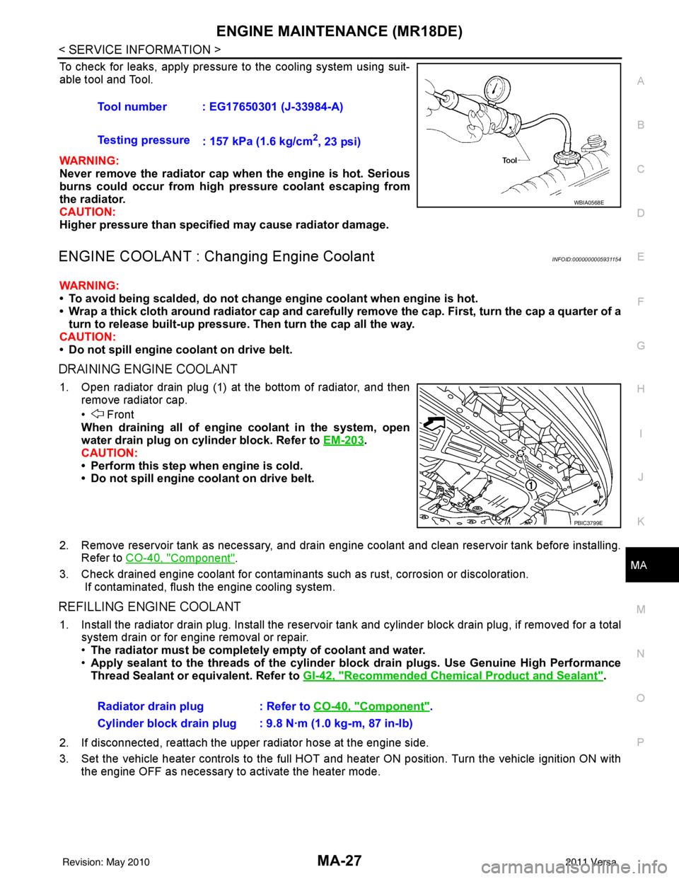
To check for leaks, apply pressure to the cooling system using suit-
able tool and Tool.
WARNING:
Never remove the radiator cap wh en the engine is hot. Serious
burns could occur from high pressure coolant escaping from
the radiator.
CAUTION:
Higher pressure than specified may cause radiator damage.
ENGINE COOLANT : Chang ing Engine CoolantINFOID:0000000005931154
WARNING:
• To avoid being scalded, do not change engine coolant when engine is hot.
• Wrap a thick cloth around radiator cap and carefully remove the cap. First, turn the cap a quarter of a
turn to release built-up pressure. Then turn the cap all the way.
CAUTION:
• Do not spill engine coolant on drive belt.
DRAINING ENGINE COOLANT
1. Open radiator drain plug (1) at the bottom of radiator, and then remove radiator cap.
• Front
When draining all of engine coolant in the system, open
water drain plug on cylinder block. Refer to EM-203
.
CAUTION:
• Perform this step when engine is cold.
• Do not spill engine coolant on drive belt.
2. Remove reservoir tank as necessary, and drain engi ne coolant and clean reservoir tank before installing.
Refer to CO-40, "
Component".
3. Check drained engine coolant for contaminants such as rust, corrosion or discoloration. If contaminated, flush the engine cooling system.
REFILLING ENGINE COOLANT
1. Install the radiator drain plug. Install the reservoir tank and cylinder block drain plug, if removed for a total
system drain or for engine removal or repair.
• The radiator must be completely empty of coolant and water.
• Apply sealant to the threads of the cylinder blo ck drain plugs. Use Genuine High Performance
Thread Sealant or equivalent. Refer to GI-42, "
Recommended Chemical Product and Sealant".
2. If disconnected, reattach the upper radiator hose at the engine side.
3. Set the vehicle heater controls to the full HOT and heat er ON position. Turn the vehicle ignition ON with
the engine OFF as necessary to activate the heater mode. Tool number : EG17650301 (J-33984-A)
Testing pressure
: 157 kPa (1.6 kg/cm
2, 23 psi)
WBIA0568E
PBIC3799E
Radiator drain plug : Refer to CO-40, "Component".
Cylinder block drain plug : 9.8 N·m (1.0 kg-m, 87 in-lb)
Revision: May 2010 2011 Versa
Page 3199 of 3787
MA-28
< SERVICE INFORMATION >
ENGINE MAINTENANCE (MR18DE)
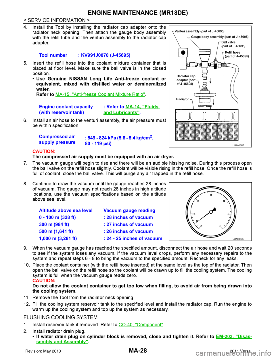
4. Install the Tool by installing the radiator cap adapter onto theradiator neck opening. Then attach the gauge body assembly
with the refill tube and the venturi assembly to the radiator cap
adapter.
5. Insert the refill hose into the coolant mixture container that is placed at floor level. Make sure the ball valve is in the closed
position.
•Use Genuine NISSAN Long Life Anti-freeze coolant or
equivalent, mixed with distil led water or demineralized
water.
Refer to MA-15, "
Anti-freeze Coolant Mixture Ratio".
6. Install an air hose to the venturi assembly, the air pressure must be within specification.
CAUTION:
The compressed air supply must be equipped with an air dryer.
7. The vacuum gauge will begin to rise and there will be an audible hissing noise. During this process open the ball valve on the refill hose slightly. Coolant will be vi sible rising in the refill hose. Once the refill hose is
full of coolant, close the ball valve. This will purge any air trapped in the refill hose.
8. Continue to draw the vacuum until the gauge reaches 28 inches of vacuum. The gauge may not reach 28 inches in high altitude
locations, use the vacuum specifications based on the altitude
above sea level.
9. When the vacuum gauge has reached the specifi ed amount, disconnect the air hose and wait 20 seconds
to see if the system loses any vacuum. If the vacuum level drops, perform any necessary repairs to the
system and repeat steps 6 - 8 to bring the vacuum to the specified amount. Recheck for any leaks.
10. Place the coolant container (with the refill hose insert ed) at the same level as the top of the radiator. Then
open the ball valve on the refill hose so the coolant will be drawn up to fill the cooling system. The cooling
system is full when the vacuum gauge reads zero.
CAUTION:
Do not allow the coolant container to get too low when filling, to avoid air from being drawn into
the cooling system.
11. Remove the Tool from the radiator neck opening.
12. Fill the cooling system reservoir tank to the specified level and install the radiator cap. Run the engine to warm up the cooling system and t op up the system as necessary.
FLUSHING COOLING SYSTEM
1. Install reservoir tank if removed. Refer to CO-40, "Component".
2. Install radiator drain plug. •If water drain plug on cylinder block is removed, close and tighten it. Refer to EM-203, "
Disas-
sembly and Assembly".
Tool number : KV991J0070 (J-45695)
Engine coolant capacity
(with reservoir tank)
: Refer to
MA-14, "
Fluids
and Lubricants".
Compressed air
supply pressure : 549 - 824 kPa (5.6 - 8.4 kg/cm
2,
80 - 119 psi)
LLIA0058E
Altitude above sea level Vacuum gauge reading
0 - 100 m (328 ft) : 28 inches of vacuum
300 m (984 ft) : 27 inches of vacuum
500 m (1,641 ft) : 26 inches of vacuum
1,000 m (3,281 ft) : 24 - 25 inches of vacuum
LLIA0057E
Revision: May 2010 2011 Versa
Page 3202 of 3787
ENGINE MAINTENANCE (MR18DE)MA-31
< SERVICE INFORMATION >
C
DE
F
G H
I
J
K
M A
B
MA
N
O P
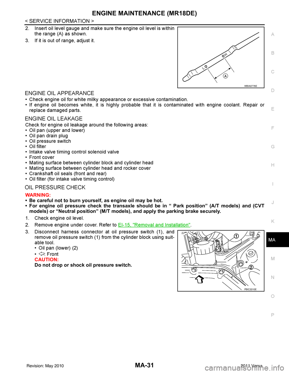
2. Insert oil level gauge and make sure the engine oil level is within the range (A) as shown.
3. If it is out of range, adjust it.
ENGINE OIL APPEARANCE
• Check engine oil for white milky appearance or excessive contamination.
• If engine oil becomes white, it is highly probable t hat it is contaminated with engine coolant. Repair or
replace damaged parts.
ENGINE OIL LEAKAGE
Check for engine oil leakage around the following areas:
• Oil pan (upper and lower)
• Oil pan drain plug
• Oil pressure switch
• Oil filter
• Intake valve timing control solenoid valve
• Front cover
• Mating surface between cylinder block and cylinder head
• Mating surface between cylinder head and rocker cover
• Crankshaft oil seals (front and rear)
• Oil filter (for intake valve timing control)
OIL PRESSURE CHECK
WARNING:
• Be careful not to burn yoursel f, as engine oil may be hot.
• For engine oil pressure check the transaxle should be in “ Park position” (A/T models) and (CVT
models) or “Neutral position” (M/T mode ls), and apply the parking brake securely.
1. Check engine oil level.
2. Remove engine under cover. Refer to EI-15, "
Removal and Installation".
3. Disconnect harness connector at oil pressure switch (1), and remove oil pressure switch (1) from the cylinder block using suit-
able tool.
• Oil pan (lower) (2)
• : Front
CAUTION:
Do not drop or shock oil pressure switch.
WBIA0776E
PBIC3310E
Revision: May 2010 2011 Versa
Page 3369 of 3787
TROUBLE DIAGNOSISMTC-53
< SERVICE INFORMATION >
C
DE
F
G H
I
K L
M A
B
MTC
N
O P
Insufficient HeatingINFOID:0000000005930855
SYMPTOM: Insufficient heating
INSPECTION FLOW
1.CONFIRM SYMPTOM BY PERFORMING OPERAT IONAL CHECK - TEMPERATURE INCREASE
1. Turn temperature control dial clockwise to maximum heat position.
2. Check for hot air at discharge air outlets.
Can the symptom be duplicated?
YES >> GO TO 3.
NO >> GO TO 2.
2.CHECK FOR ANY SYMPTOMS
Perform a complete operational check for any symptoms. Refer to MTC-31, "
Operational Check" .
Does another symptom exist?
YES >> Refer to MTC-23, "How to Perform Trouble Diagnosis for Quick and Accurate Repair" .
NO >> System OK.
3.CHECK FOR SERVICE BULLETINS
Check for any service bulletins.
>> GO TO 4.
4.CHECK COOLANT SYSTEM
1. Check engine coolant level. Refer to CO-11, "
Inspection" (HR16DE) or CO-36, "Inspection" (MR18DE).
2. Check hoses for leaks or kinks.
3. Check Radiator cap. Refer to CO-14, "
Checking Radiator Cap" HR16DE or CO-39, "Checking Radiator
Cap" (MR18DE).
OK or NG
OK >> GO TO 5.
NG >> Repair/replace as necessary.
5.CHECK AIR MIX DOOR CABLE
Check air mix door cable operation. Refer to MTC-65, "
Air Mix Door Cable Adjustment" .
OK or NG
Gauge indication Refrigerant cycleProbable causeCorrective action
Low-pressure side becomes nega-
tive. Liquid tank or front/rear side of
expansion valve’s pipe is frost-
ed or dewed.High-pressure side is closed
and refrigerant does not flow.
↓
Expansion valve or liquid tank
is frosted.Leave the system at rest until
no frost is present. Start it
again to check whether or not
the malfunction is caused by
water or foreign particles.
• If water is the cause, initially
cooling is okay. Then the wa-
ter freezes causing a block-
age. Drain water from
refrigerant or replace refrig-
erant.
• If due to foreign particles, re-
move expansion valve and
remove the particles with dry
and compressed air (not
shop air).
• If either of the above meth- ods cannot correct the mal-
function, replace expansion
valve.
• Replace liquid tank.
• Check oil for contamination.
AC362A
Revision: May 2010 2011 Versa
Page 3370 of 3787
MTC-54
< SERVICE INFORMATION >
TROUBLE DIAGNOSIS
YES >> GO TO 6.
NO >> Adjust or replace air mix door cable. Refer to MTC-65, "
Air Mix Door Cable Adjustment" .
6.CHECK AIR DUCTS
Check ducts for air leaks.
OK or NG
OK >> GO TO 7.
NG >> Repair air leaks.
7.CHECK HEATER HOSE TEMPERATURES
1. Start engine and warm it up to normal operating temperature.
2. Touch both the inlet and outlet heater hoses. The inlet hose should be hot and the outlet hose should be
warm.
Is the inlet hose hot and the outlet hose warm?
YES >> GO TO 8.
NO >> Both hoses warm: GO TO 9.
8.CHECK ENGINE COOLANT TEMPERATURE SENSOR
Check engine control temperature sensor. Refer to EC-172, "
Component Inspection" (MR18DE) or EC-690,
"Component Inspection" (HR16DE).
OK or NG
OK >> System OK.
NG >> Repair or replace as necessary. Retest.
9.CHECK HEATER HOSES
Check heater hoses for proper installation.
OK or NG
OK >> GO TO 10.
NG >> Repair /replace as necessary. Retest GO TO 7.
10.BACK FLUSH HEATER CORE
1. Back flush heater core.
2. Drain the water from the system.
3. Refill system with new engine coolant. Refer to CO-11, "
Changing Engine Coolant" (HR16DE) or CO-36,
"Changing Engine Coolant" (MR18DE) .
4. Start engine and warm it up to normal operating temperature.
5. Touch both the inlet and outlet heater hoses. The inlet hose should be hot and the outlet hose should be
warm.
Is the inlet hose hot and the outlet hose warm?
YES >> System OK.
NO >> Replace heater core and refill engine coolant. Refer to MTC-68, "
Removal and Installation" .
NoiseINFOID:0000000005930856
SYMPTOM: Noise
INSPECTION FLOW
Revision: May 2010 2011 Versa
Page 3375 of 3787
A/C UNIT ASSEMBLYMTC-59
< SERVICE INFORMATION >
C
DE
F
G H
I
K L
M A
B
MTC
N
O P
A/C UNIT ASSEMBLY
Removal and InstallationINFOID:0000000005930860
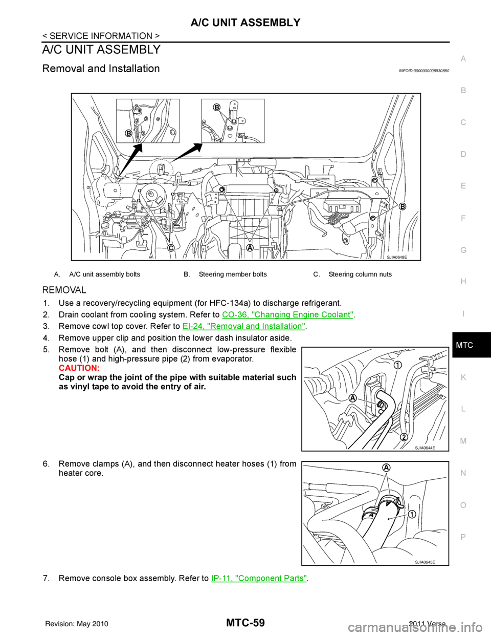
REMOVAL
1. Use a recovery/recycling equipment (f or HFC-134a) to discharge refrigerant.
2. Drain coolant from cooling system. Refer to CO-36, "
Changing Engine Coolant".
3. Remove cowl top cover. Refer to EI-24, "
Removal and Installation".
4. Remove upper clip and position the lower dash insulator aside.
5. Remove bolt (A), and then disconnect low-pressure flexible hose (1) and high-pressure pipe (2) from evaporator.
CAUTION:
Cap or wrap the joint of the pi pe with suitable material such
as vinyl tape to avoid the entry of air.
6. Remove clamps (A), and then disconnect heater hoses (1) from heater core.
7. Remove console box assembly. Refer to IP-11, "
Component Parts".
A. A/C unit assembly boltsB. Steering member boltsC. Steering column nuts
SJIA0648E
SJIA0644E
SJIA0645E
Revision: May 2010 2011 Versa
Page 3376 of 3787
MTC-60
< SERVICE INFORMATION >
A/C UNIT ASSEMBLY
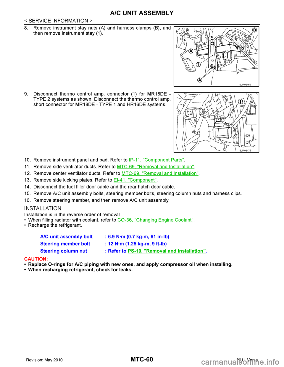
8. Remove instrument stay nuts (A) and harness clamps (B), andthen remove instrument stay (1).
9. Disconnect thermo control amp. connector (1) for MR18DE - TYPE 2 systems as shown. Di sconnect the thermo control amp.
short connector for MR18DE - TYPE 1 and HR16DE systems.
10. Remove instrument panel and pad. Refer to IP-11, "
Component Parts".
11. Remove side ventilator ducts. Refer to MTC-69, "
Removal and Installation".
12. Remove center ventilator ducts. Refer to MTC-69, "
Removal and Installation".
13. Remove side kicking plates. Refer to EI-41, "
Component".
14. Disconnect the fuel filler door cable and the rear hatch door cable.
15. Remove A/C unit assembly bolts, steering member bolts, steering column nuts and harness clips.
16. Remove steering member, and then remove A/C unit assembly.
INSTALLATION
Installation is in the reverse order of removal.
• When filling radiator with coolant, refer to CO-36, "
Changing Engine Coolant".
• Recharge the refrigerant.
CAUTION:
• Replace O-rings for A/C piping with new ones, and apply compressor oil when installing.
• When recharging refrigerant, check for leaks.
SJIA0646E
SJIA0647E
A/C unit assembly bolt : 6.9 N·m (0.7 kg-m, 61 in-lb)
Steering member bolt : 12 N·m (1.25 kg-m, 9 ft-lb)
Steering column nut : Refer to PS-10, "
Removal and Installation".
Revision: May 2010 2011 Versa
Page 3466 of 3787
PG-46
< SERVICE INFORMATION >
HARNESS
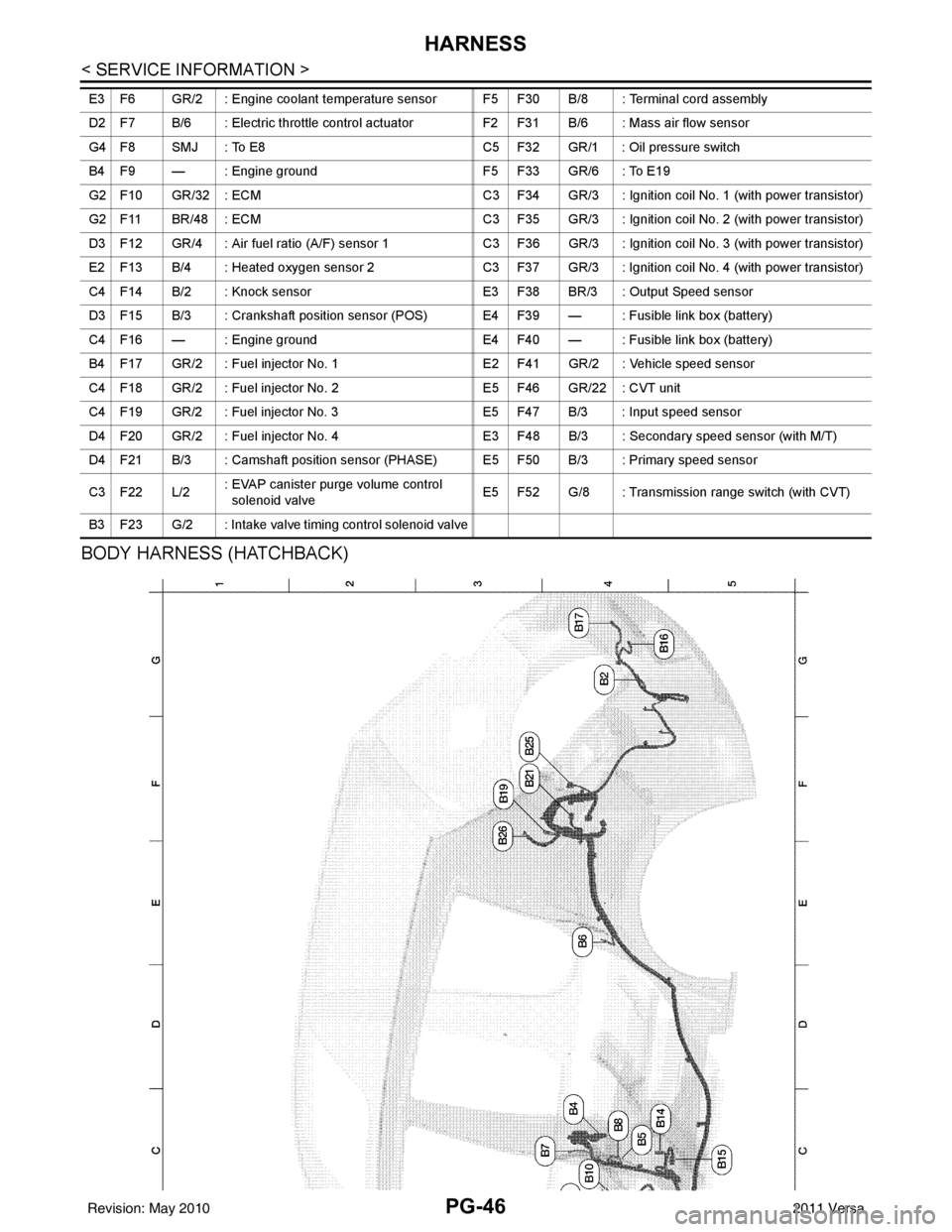
BODY HARNESS (HATCHBACK)
E3 F6 GR/2 : Engine coolant temperature sensor F5 F30 B/8 : Terminal cord assembly
D2 F7 B/6 : Electric throttle control actuatorF2 F31 B/6 : Mass air flow sensor
G4 F8 SMJ : To E8 C5 F32 GR/1 : Oil pressure switch
B4 F9 — : Engine ground F5 F33 GR/6 : To E19
G2 F10 GR/32 : ECM C3 F34 GR/3 : Ignition coil No. 1 (with power transistor)
G2 F11 BR/48 : ECM C3 F35 GR/3 : Ignition coil No. 2 (with power transistor)
D3 F12 GR/4 : Air fuel ratio (A/F) sensor 1 C3 F36 GR/3 : Ignition coil No. 3 (with power transistor)
E2 F13 B/4 : Heated oxygen sensor 2 C3 F37 GR/3 : Ignition coil No. 4 (with power transistor)
C4 F14 B/2 : Knock sensor E3 F38 BR/3 : Output Speed sensor
D3 F15 B/3 : Crankshaft position sensor (POS) E4 F39 — : Fusible link box (battery)
C4 F16 — : Engine ground E4 F40 — : Fusible link box (battery)
B4 F17 GR/2 : Fuel injector No. 1 E2 F41 GR/2 : Vehicle speed sensor
C4 F18 GR/2 : Fuel injector No. 2E5 F46 GR/22 : CVT unit
C4 F19 GR/2 : Fuel injector No. 3 E5 F47 B/3 : Input speed sensor
D4 F20 GR/2 : Fuel injector No. 4 E3 F48 B/3 : Secondary speed sensor (with M/T)
D4 F21 B/3 : Camshaft position sensor (PHASE) E5 F50 B/3 : Primary speed sensor
C3 F22 L/2 : EVAP canister purge volume control
solenoid valve E5 F52 G/8 : Transmission range switch (with CVT)
B3 F23 G/2 : Intake valve timing control solenoid valve
Revision: May 2010 2011 Versa