Page 3478 of 3787

PG-58
< SERVICE INFORMATION >
HARNESS
Wiring Diagram Codes (Cell Codes)
INFOID:0000000005928356
Use the chart below to find out what each wiring diagram code stands for.
Refer to the wiring diagram code in the alphabetical index to find the location (page number) of each wiring
diagram.
D4 D406 W/2 : Back door request switch C2 D413 B/1 : Rear window defogger (-)
E2 D407 W/2 : High mounted stop lamp
Code Section Wiring Diagram Name
ABS BRC Anti-lock Brake System
A/C,M MTC Manual Air Conditioner
APPS1 EC Accelerator Pedal Position Sensor
A/F EC Air Fuel Ratio Sensor 1
A/FH EC Air Fuel Ratio Sensor 1 Heater
APPS2 EC Accelerator Pedal Position Sensor
APPS3 EC Accelerator Pedal Position Sensor
ASC/BS EC ASCD Brake Switch
ASC/SW EC ASCD Steering Switch
ASCBOF EC ASCD Brake Switch
ASCIND EC ASCD Indicator
AT/IND DI A/T Indicator Lamp
AUDIO AV Audio
BACK/L LT Back-up Lamp
BA/FTS AT A/T Fluid Temperature Sensor and TCM Power Supply
B/DOOR BL Back Door Opener
BRK/SW EC Brake Switch
CAN AT CAN Communication Line
CAN CVT CAN Communication Line
CAN EC CAN Communication Line
CAN LAN CAN System
CHARGE SC Charging System
CHIME DI Warning Chime
COOL/F EC Cooling Fan Control
COMBSW LT Combination Switch
COMM AV Audio Visual Communication System
CVTIND DI CVT Indicator Lamp
D/LOCK BL Power Door Lock
DEF GW Rear Window Defogger
DTRL LT Headlamp - With Daytime Light System
ECTS EC Engine Coolant Temperature Sensor
ENGSS AT Engine Speed Signal
EPS STC Electronic Controlled Power Steering
ETC1 EC Electric Throttle Control Function
ETC2 EC Throttle Control Motor Relay
ETC3 EC Throttle Control Motor
F/FOG LT Front Fog Lamp
F/PUMP EC Fuel Pump
FTS AT A/T Fluid Temperature Sensor
FTS CVT CVT Fluid Temperature Sensor Circuit
FTTS EC Fuel Tank Temperature Sensor
FUEL EC Fuel Ignition System Function
HEATER MTC Heater System
Revision: May 2010 2011 Versa
Page 3556 of 3787

PRECAUTIONSRSU-3
< SERVICE INFORMATION >
C
DF
G H
I
J
K L
M A
B
RSU
N
O P
5. When the repair work is completed, return the ignition switch to the ″LOCK ″ position before connecting
the battery cables. (At this time, the steering lock mechanism will engage.)
6. Perform a self-diagnosis check of al l control units using CONSULT-III.
Precaution for Rear SuspensionINFOID:0000000005931081
• When installing the rubber bushings, the final tightening must be done under unladen condition and with the
tires on level ground. Oil will shorten the life of the rubber bushings, so wipe off any spilled oil immediately.
• Unladen condition means the fuel tank, engine coolant and lubricants are at the full specification. The spare
tire, jack, hand tools, and mats are in their designated positions.
• After installing suspension components, check the wheel alignment.
• Caulking nuts are not reusable. Always use new caulking nuts for installation. New caulking nuts are pre- oiled, do not apply any additional lubrication.
Revision: May 2010 2011 Versa
Page 3559 of 3787

RSU-6
< SERVICE INFORMATION >
REAR SUSPENSION ASSEMBLY
REAR SUSPENSION ASSEMBLY
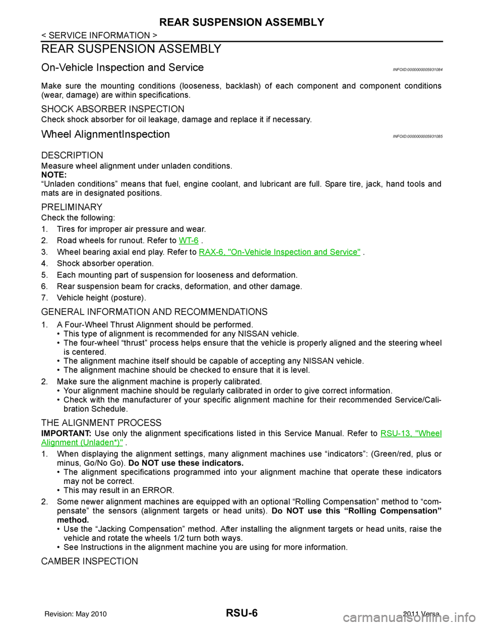
On-Vehicle Inspection and ServiceINFOID:0000000005931084
Make sure the mounting conditions (looseness, backlash) of each component and component conditions
(wear, damage) are within specifications.
SHOCK ABSORBER INSPECTION
Check shock absorber for oil leakage, damage and replace it if necessary.
Wheel AlignmentInspectionINFOID:0000000005931085
DESCRIPTION
Measure wheel alignment under unladen conditions.
NOTE:
“Unladen conditions” means that fuel, engine coolant, and lubricant are full. Spare tire, jack, hand tools and
mats are in designated positions.
PRELIMINARY
Check the following:
1. Tires for improper air pressure and wear.
2. Road wheels for runout. Refer to WT-6
.
3. Wheel bearing axial end play. Refer to RAX-6, "
On-Vehicle Inspection and Service" .
4. Shock absorber operation.
5. Each mounting part of suspension for looseness and deformation.
6. Rear suspension beam for cracks, deformation, and other damage.
7. Vehicle height (posture).
GENERAL INFORMATION AND RECOMMENDATIONS
1. A Four-Wheel Thrust Alignment should be performed. • This type of alignment is recommended for any NISSAN vehicle.
• The four-wheel “thrust” process helps ensure that the vehicle is properly aligned and the steering wheel
is centered.
• The alignment machine itself should be ca pable of accepting any NISSAN vehicle.
• The alignment machine should be checked to ensure that it is level.
2. Make sure the alignment machine is properly calibrated. • Your alignment machine should be regularly calibrated in order to give correct information.
• Check with the manufacturer of your specific al ignment machine for their recommended Service/Cali-
bration Schedule.
THE ALIGNMENT PROCESS
IMPORTANT: Use only the alignment specifications listed in this Service Manual. Refer to RSU-13, "Wheel
Alignment (Unladen*)" .
1. When displaying the alignment settings, many alignment machines use “indicators”: (Green/red, plus or minus, Go/No Go). Do NOT use these indicators.
• The alignment specifications programmed into your alignment machine that operate these indicators may not be correct.
• This may result in an ERROR.
2. Some newer alignment machines are equipped with an optional “Rolling Compensation” method to “com- pensate” the sensors (alignment targets or head units). Do NOT use this “Rolling Compensation”
method.
• Use the “Jacking Compensation” method. After inst alling the alignment targets or head units, raise the
vehicle and rotate the wheels 1/2 turn both ways.
• See Instructions in the alignment machine you are using for more information.
CAMBER INSPECTION
Revision: May 2010 2011 Versa
Page 3566 of 3787

SERVICE DATA AND SPECIFICATIONS (SDS)RSU-13
< SERVICE INFORMATION >
C
DF
G H
I
J
K L
M A
B
RSU
N
O P
SERVICE DATA AND SPECIFICATIONS (SDS)
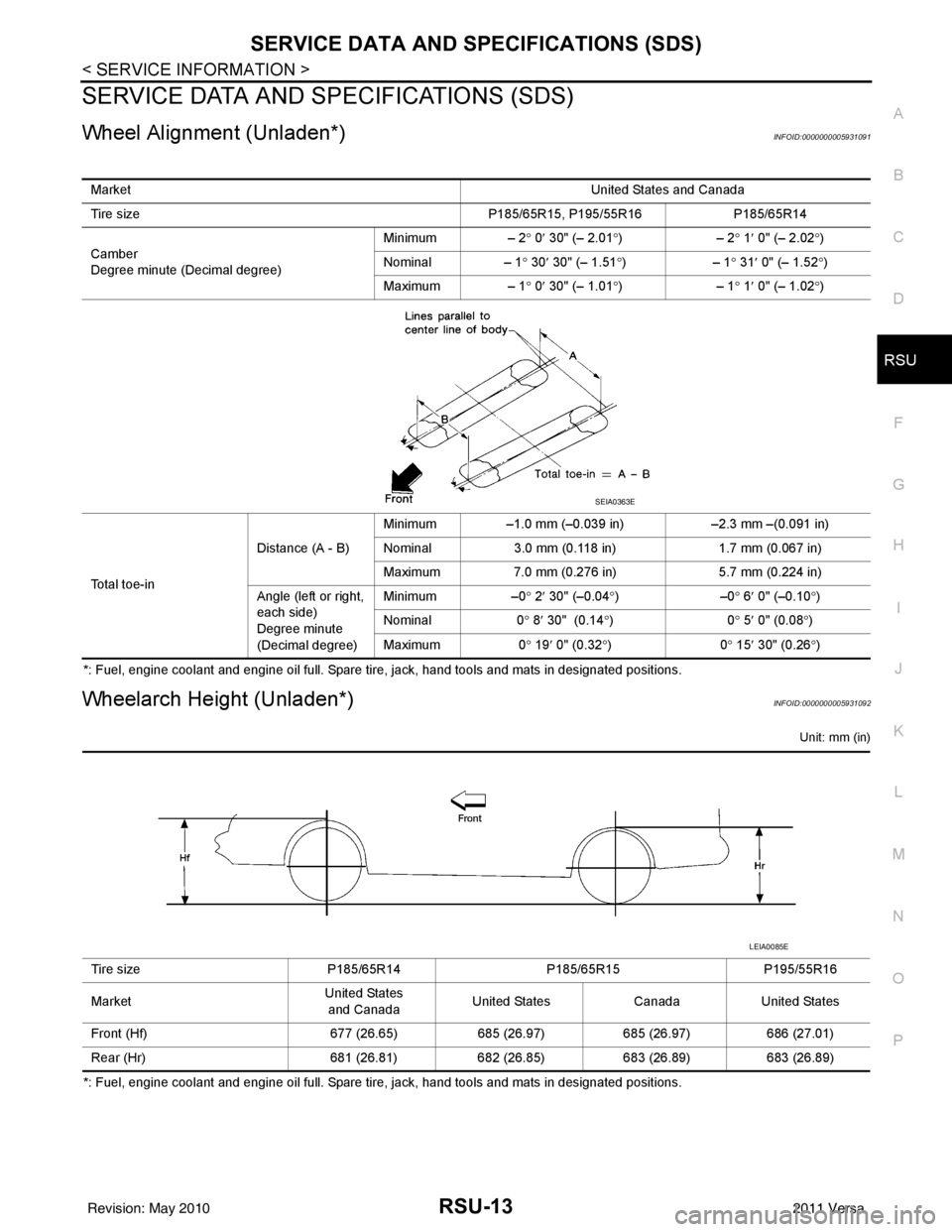
Wheel Alignment (Unladen*)INFOID:0000000005931091
*: Fuel, engine coolant and engine oil full. Spare tire, jack, hand tools and mats in designated positions.
Wheelarch Height (Unladen*)INFOID:0000000005931092
Unit: mm (in)
*: Fuel, engine coolant and engine oil full. Spare tire, jack, hand tools and mats in designated positions. Market
United States and Canada
Tire size P185/65R15, P195/55R16 P185/65R14
Camber
Degree minute (Decimal degree) Minimum – 2°
0′ 30" (– 2.01 °)– 2 ° 1 ′ 0" (– 2.02 °)
Nominal – 1 ° 30 ′ 30" (– 1.51 °)– 1° 31 ′ 0" (– 1.52 °)
Maximum – 1° 0′ 30" (– 1.01 °)– 1° 1 ′ 0" (– 1.02 °)
To t a l t o e - i n Distance (A - B)
Minimum
–1.0 mm (–0.039 in) –2.3 mm –(0.091 in)
Nominal 3.0 mm (0.118 in) 1.7 mm (0.067 in)
Maximum 7.0 mm (0.276 in) 5.7 mm (0.224 in)
Angle (left or right,
each side)
Degree minute
(Decimal degree) Minimum
–0° 2 ′ 30" (–0.04 °)– 0° 6 ′ 0" (–0.10 °)
Nominal 0° 8 ′ 30" (0.14 °)0 ° 5 ′ 0" (0.08 °)
Maximum 0° 19 ′ 0" (0.32 °)0 ° 15 ′ 30" (0.26 °)
SEIA0363E
Tire size P185/65R14P185/65R15P195/55R16
Market United States
and Canada United States
CanadaUnited States
Front (Hf) 677 (26.65)685 (26.97)685 (26.97)686 (27.01)
Rear (Hr) 681 (26.81)682 (26.85)683 (26.89)683 (26.89)
LEIA0085E
Revision: May 2010 2011 Versa
Page 3597 of 3787

STARTING SYSTEMSC-19
< SERVICE INFORMATION >
C
DE
F
G H
I
J
L
M A
B
SC
N
O P
• 10A fuse (No. 49, M/T model s, located in the IPDM E/R)
• 15A fuse (No. 52, located in the IPDM E/R)
• 20A fuse (No. 53, located in the IPDM E/R)
• Transmission range switch, clutch interlock switch or TCM depending on equipment
• Ignition switch
• Ignition relay IPDM E/R
• Starter relay IPDM E/R
• Starter relay request ON signal from BCM
• Harness for open or short circuit
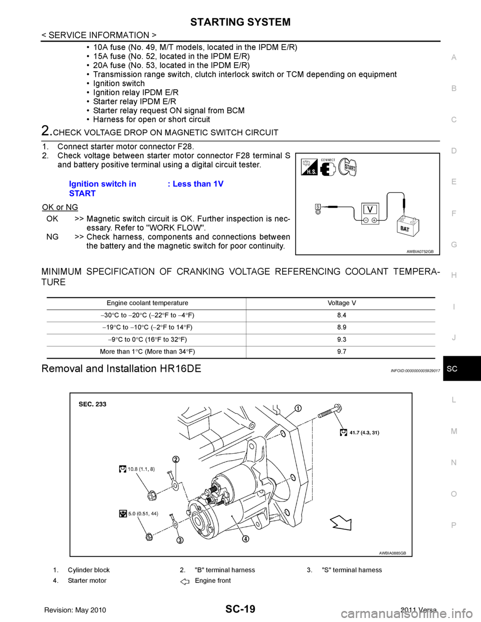
2.CHECK VOLTAGE DROP ON MAGNETIC SWITCH CIRCUIT
1. Connect starter motor connector F28.
2. Check voltage between starter motor connector F28 terminal S and battery positive terminal using a digital circuit tester.
OK or NG
OK >> Magnetic switch circuit is OK. Further inspection is nec-
essary. Refer to "WORK FLOW".
NG >> Check harness, components and connections between the battery and the magnetic switch for poor continuity.
MINIMUM SPECIFICATION OF CRANKING VO LTAGE REFERENCING COOLANT TEMPERA-
TURE
Removal and Installation HR16DEINFOID:0000000005929017
Ignition switch in
START : Less than 1V
AWBIA0752GB
Engine coolant temperature
Voltage V
− 30 °C to − 20°C ( −22 °F to −4 °F) 8.4
− 19 °C to − 10°C ( −2°F to 14 °F) 8.9
− 9 °C to 0 °C (16 °F to 32 °F) 9.3
More than 1 °C (More than 34 °F) 9.7
1. Cylinder block2. "B" terminal harness3. "S" terminal harness
4. Starter motor Engine front
AWBIA0885GB
Revision: May 2010 2011 Versa