2011 NISSAN LATIO fuse box
[x] Cancel search: fuse boxPage 2721 of 3787
HOW TO USE THIS MANUALGI-17
< SERVICE INFORMATION >
C
DE
F
G H
I
J
K L
M B
GI
N
O P
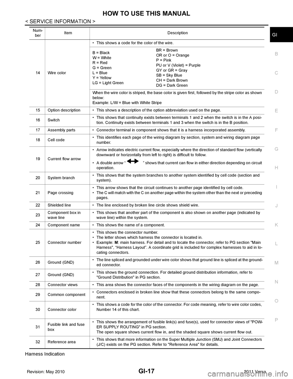
Harness Indication
14 Wire color • This shows a code for the color of the wire.
B = Black
W = White
R = Red
G = Green
L = Blue
Y = Yellow
LG = Light Green BR = Brown
OR or O = Orange
P = Pink
PU or V (Violet) = Purple
GY or GR = Gray
SB = Sky Blue
CH = Dark Brown
DG = Dark Green
When the wire color is striped, the base color is given first, followed by the stripe color as shown
below:
Example: L/W = Blue with White Stripe
15 Option description • This shows a description of the option abbreviation used on the page.
16 Switch • This shows that continuity exists between terminals 1 and 2 when the switch is in the A posi-
tion. Continuity exists between terminals 1 and 3 when the switch is in the B position.
17 Assembly parts • Connector terminal in component shows that it is a harness incorporated assembly.
18 Cell code • This identifies each page of the wiring diagram by section, system and wiring diagram page
number.
19 Current flow arrow • Arrow indicates electric current flow, especially where the direction of standard flow (vertically
downward or horizontally from left to right) is difficult to follow.
• A double arrow “ ” shows that current can flow in either direction depending on circuit operation.
20 System branch • This shows that the system branches to another system identified by cell code (section and
system).
21 Page crossing • This arrow shows that the circuit continues to another page identified by cell code.
• The C will match with the C on another page within the system other than the next or preceding
pages.
22 Shielded line • The line enclosed by broken line circle shows shield wire.
23 Component box in
wave line • This shows that another part of the component is also shown on another page (indicated by
wave line) within the system.
24 Component name • This shows the name of a component.
25 Connector number • This shows the connector number.
• The letter shows which harness the connector is located in.
•Example:
M: main harness. For detail and to locate the connector, refer to PG section "Main
Harness", “Harness Layout”. A coordinate grid is included for complex harnesses to aid in lo-
cating connectors.
26 Ground (GND) • The line spliced and grounded under wire color shows that ground line is spliced at the ground-
ed connector.
27 Ground (GND) • This shows the ground connection. For detailed ground distribution information, refer to
"Ground Distribution" in PG section.
28 Connector views • This area shows the connector faces of the components in the wiring diagram on the page.
29 Common component • Connectors enclosed in broken line show that these connectors belong to the same compo-
nent.
30 Connector color • This shows a code for the color of the connector. For code meaning, refer to wire color codes,
Number 14 of this chart.
31 Fusible link and fuse
box • This shows the arrangement of fusible link(s) and fuse(s), used for connector views of "POW-
ER SUPPLY ROUTING" in PG section.
The open square shows current flow in, and the shaded square shows current flow out.
32 Reference area • This shows that more information on the Super Multiple Junction (SMJ) and Joint Connectors
(J/C) exists on the PG section. Refer to "Reference Area" for details.
Num-
ber Item
Description
Revision: May 2010 2011 Versa
Page 2773 of 3787
POWER WINDOW SYSTEMGW-19
< SERVICE INFORMATION >
C
DE
F
G H
J
K L
M A
B
GW
N
O P
POWER WINDOW SYSTEM
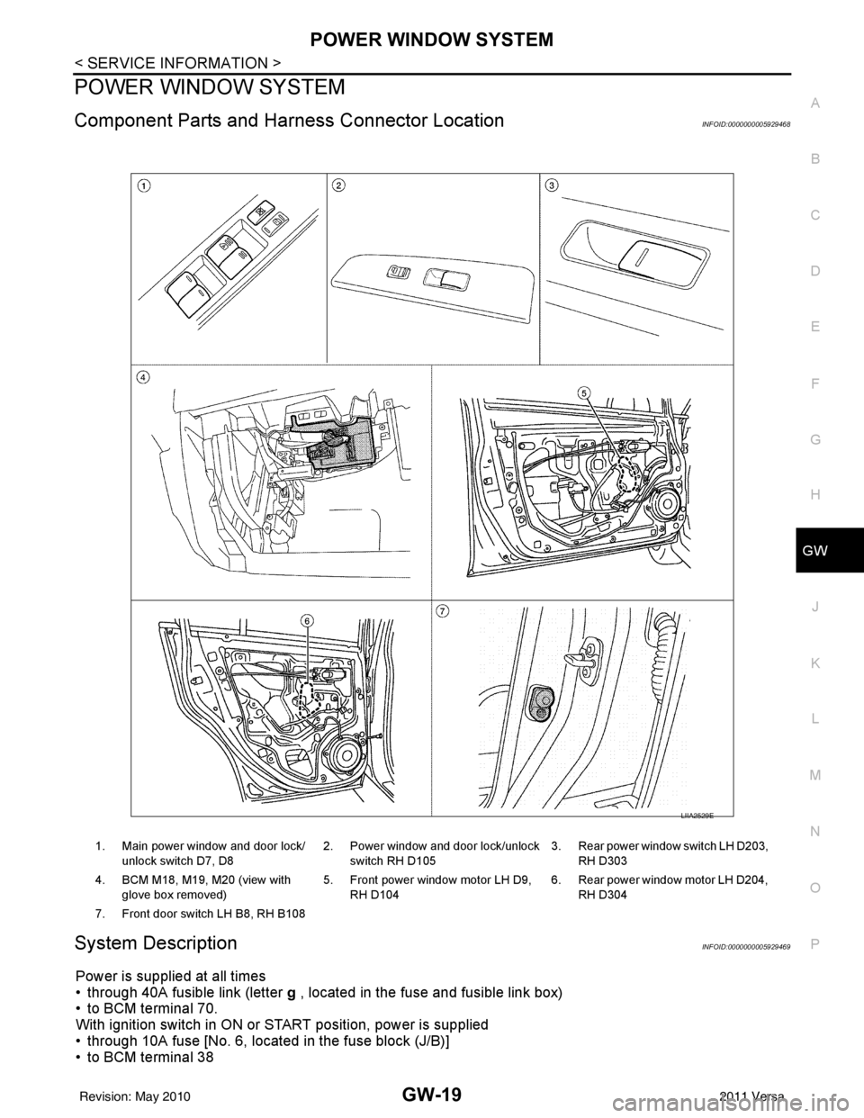
Component Parts and Har ness Connector LocationINFOID:0000000005929468
System DescriptionINFOID:0000000005929469
Power is supplied at all times
• through 40A fusible link (letter g , located in the fuse and fusible link box)
• to BCM terminal 70.
With ignition switch in ON or START position, power is supplied
• through 10A fuse [No. 6, located in the fuse block (J/B)]
• to BCM terminal 38
1. Main power window and door lock/
unlock switch D7, D8 2. Power window and door lock/unlock
switch RH D105 3. Rear power window switch LH D203,
RH D303
4. BCM M18, M19, M20 (view with glove box removed) 5. Front power window motor LH D9,
RH D104 6. Rear power window motor LH D204,
RH D304
7. Front door switch LH B8, RH B108
LIIA2529E
Revision: May 2010 2011 Versa
Page 2806 of 3787

GW-52
< SERVICE INFORMATION >
REAR WINDOW DEFOGGER
Power is supplied at all times
• through 15A fuses (No. 46 and 47, located in the IPDM E/R)
• to rear window defogger relay
• through 10A fuse [No. 5 (with heated mirrors), located in the fuse block (J/B)]
• to heated mirror relay terminal 3
• through 40A fusible link (letter g , located in the fuse and fusible link box)
• to BCM terminal 70.
With the ignition switch turned to ON or START position, power is supplied
• through ignition relay
• to rear window defogger relay (located in the IPDM E/R)
• through 10A fuse [No. 6, located in the fuse block (J/B)]
• to BCM terminal 38.
Ground is supplied
• to BCM terminal 67 and
• to front air control terminal 8
• through body grounds M57 and M61
• to IPDM E/R terminals 39 and 59
• through body grounds E15 and E24.
When front air control (rear window defogger switch) is turned to ON, ground is supplied
• to BCM terminal 9
• through front air control terminal 3
• through front air control terminal 8
• through body grounds M57 and M61.
Then rear window defogger switch is illuminated.
Then BCM recognizes that rear window defogger switch is turned to ON.
Then it sends rear window defogger switch signals to IPDM E/R via CAN communication (CAN-H, CAN-L).
When IPDM E/R receives rear window defogger switch signals, ground is supplied
• to rear window defogger relay (located in the IPDM E/R)
• through IPDM E/R terminals 39 and 59
• through body grounds E15 and E24
Then rear window defogger relay is energized.
With power and ground supplied, rear window def ogger filaments heat and defog the rear window.
When rear window defogger relay is turned to ON (with heated mirrors), power is supplied
• through heated mirror relay terminal 5
• to door mirror (LH and RH) terminal 1.
Door mirror (LH and RH) is grounded through body grounds M57 and M61.
With power and ground supplied, rear window defogger filaments heat and defog the rear window and door
mirror filaments heat and defog the mirrors.
CAN Communication System DescriptionINFOID:0000000005929499
Refer to LAN-7, "System Description".
Revision: May 2010 2011 Versa
Page 2833 of 3787
IP-12
< ON-VEHICLE REPAIR >
INSTRUMENT PANEL ASSEMBLY
Removal and Installation
INFOID:0000000005929593
CAUTION:
• Disconnect both the negative and positive battery terminals, then wait at least three minutes.
• Never tamper with or force air bag lid open, as this may adversely affect air bag performance.
• Be careful not to scratch pad and other parts.
INSTRUMENT PANEL ASSEMBLY
Removal
1. Disconnect both the negative and positive battery terminals, then wait at least three minutes.
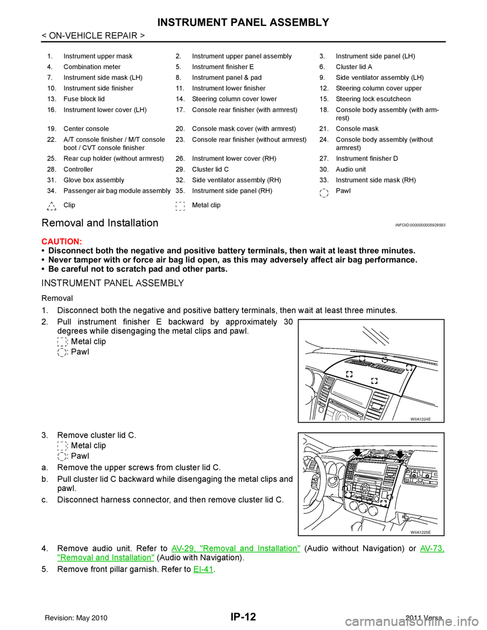
2. Pull instrument finisher E backward by approximately 30
degrees while disengaging the metal clips and pawl.
: Metal clip
: Pawl
3. Remove cluster lid C. : Metal clip
: Pawl
a. Remove the upper screws from cluster lid C.
b. Pull cluster lid C backward while disengaging the metal clips and pawl.
c. Disconnect harness connector, and then remove cluster lid C.
4. Remove audio unit. Refer to AV-29, "
Removal and Installation" (Audio without Navigation) or AV-73,
"Removal and Installation" (Audio with Navigation).
5. Remove front pillar garnish. Refer to EI-41
.
1. Instrument upper mask 2. Instrument upper panel assembly 3. Instrument side panel (LH)
4. Combination meter 5. Instrument finisher E 6. Cluster lid A
7. Instrument side mask (LH) 8. Instrument panel & pad 9. Side ventilator assembly (LH)
10. Instrument side finisher 11. Instrument lower finisher 12. Steering column cover upper
13. Fuse block lid 14. Steering column cover lower 15. Steering lock escutcheon
16. Instrument lower cover (LH) 17. Console rear finisher (with armrest) 18. Console body assembly (with arm- rest)
19. Center console 20. Console mask cover (with armrest) 21. Console mask
22. A/T console finisher / M/T console boot / CVT console finisher 23. Console rear finisher (without armrest) 24. Console body assembly (without
armrest)
25. Rear cup holder (without armrest) 26. Instrument lower cover (RH) 27. Instrument finisher D
28. Controller 29. Cluster lid C 30. Audio unit
31. Glove box assembly 32. Side ventilator assembly (RH) 33. Instrument side mask (RH)
34. Passenger air bag module assembly 35. Instrument side panel (RH) Pawl
Clip Metal clip
WIIA1224E
WIIA1225E
Revision: May 2010 2011 Versa
Page 2835 of 3787
IP-14
< ON-VEHICLE REPAIR >
INSTRUMENT PANEL ASSEMBLY
10. Remove steering lock escutcheon.
11. Remove the steering column cover screws, then disengage pawls and remove the steering column cov-
ers.
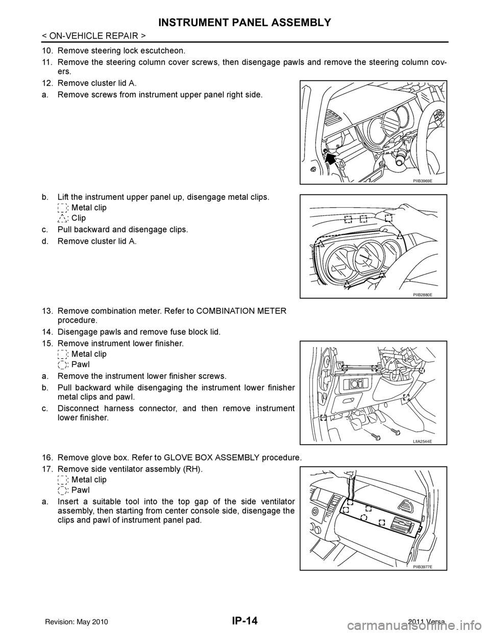
12. Remove cluster lid A.
a. Remove screws from instrument upper panel right side.
b. Lift the instrument upper panel up, disengage metal clips. : Metal clip
: Clip
c. Pull backward and disengage clips.
d. Remove cluster lid A.
13. Remove combination meter. Refer to COMBINATION METER procedure.
14. Disengage pawls and remove fuse block lid.
15. Remove instrument lower finisher. : Metal clip
: Pawl
a. Remove the instrument lower finisher screws.
b. Pull backward while disengaging the instrument lower finisher metal clips and pawl.
c. Disconnect harness connector, and then remove instrument lower finisher.
16. Remove glove box. Refer to GLOVE BOX ASSEMBLY procedure.
17. Remove side ventilator assembly (RH). : Metal clip
: Pawl
a. Insert a suitable tool into the top gap of the side ventilator assembly, then starting from center console side, disengage the
clips and pawl of instrument panel pad.
PIIB3969E
PIIB2880E
LIIA2544E
PIIB3977E
Revision: May 2010 2011 Versa
Page 2842 of 3787
INSTRUMENT PANEL ASSEMBLYIP-21
< ON-VEHICLE REPAIR >
C
DE
F
G H
J
K L
M A
B
IP
N
O P
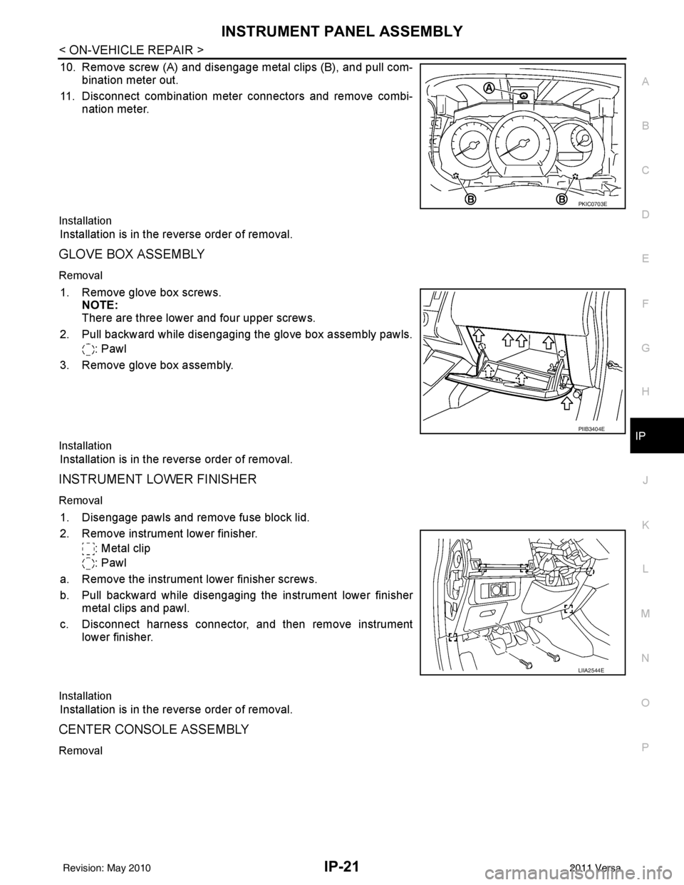
10. Remove screw (A) and disengage metal clips (B), and pull com- bination meter out.
11. Disconnect combination meter connectors and remove combi- nation meter.
Installation
Installation is in the reverse order of removal.
GLOVE BOX ASSEMBLY
Removal
1. Remove glove box screws.NOTE:
There are three lower and four upper screws.
2. Pull backward while disengaging the glove box assembly pawls. : Pawl
3. Remove glove box assembly.
Installation
Installation is in the reverse order of removal.
INSTRUMENT LOWER FINISHER
Removal
1. Disengage pawls and remove fuse block lid.
2. Remove instrument lower finisher. : Metal clip
: Pawl
a. Remove the instrument lower finisher screws.
b. Pull backward while disengaging the instrument lower finisher metal clips and pawl.
c. Disconnect harness connector, and then remove instrument lower finisher.
Installation
Installation is in the reverse order of removal.
CENTER CONSOLE ASSEMBLY
Removal
PKIC0703E
PIIB3404E
LIIA2544E
Revision: May 2010 2011 Versa
Page 3037 of 3787
HEADLAMP (FOR USA)LT-5
< SERVICE INFORMATION >
C
DE
F
G H
I
J
L
M A
B
LT
N
O P
HEADLAMP (FOR USA)
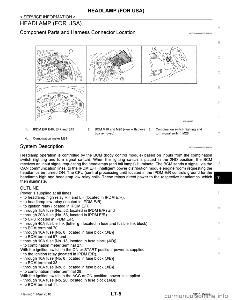
Component Parts and Har ness Connector LocationINFOID:0000000005929028
System DescriptionINFOID:0000000005929029
Headlamp operation is controlled by the BCM (body c ontrol module) based on inputs from the combination
switch (lighting and turn signal switch). When the light ing switch is placed in the 2ND position, the BCM
receives an input signal requesting the headlamps (and tail lamps) illuminate. The BCM sends a signal, via the
CAN communication lines, to the IPDM E/R (intelligent power distribution module engine room) requesting the
headlamps be turned ON. The CPU (centra l processing unit) located in the IPDM E/R controls ground for the
headlamp high and headlamp low relay coils. These relays direct power to the respective headlamps, which
then illuminate.
OUTLINE
Power is supplied at all times
• to headlamp high relay RH and LH (located in IPDM E/R),
• to headlamp low relay (located in IPDM E/R),
• to ignition relay (located in IPDM E/R),
• through 15A fuse (No. 52, located in IPDM E/R) and
• through 20A fuse (No. 53, located in IPDM E/R)
• to CPU located in IPDM E/R,
• through 40A fusible link (letter g , located in fuse and fusible link block)
• to BCM terminal 70,
• through 10A fuse [No. 8, located in fuse block (J/B)]
• to BCM terminal 57, and
• through 10A fuse [No. 13, located in fuse block (J/B)]
• to combination meter terminal 27.
With the ignition switch in the ON or START position, power is supplied
• to the ignition relay (located in IPDM E/R),
• through 10A fuse [No. 6, located in fuse block (J/B)]
• to BCM terminal 38,
• through 10A fuse [No. 3, located in fuse block (J/B)]
• to combination meter terminal 28.
With the ignition switch in the ACC or ON position, power is supplied
• through 10A fuse [No. 20, located in fuse block (J/B)]
• to BCM terminal 11.
1. IPDM E/R E46, E47 and E48 2. BCM M18 and M20 (view with glove
box removed)3. Combination switch (lighting and
turn signal switch) M28
4. Combination meter M24
WKIA5469E
Revision: May 2010 2011 Versa
Page 3059 of 3787
HEADLAMP (FOR CANADA) - DAYTIME LIGHT SYSTEM -
LT-27
< SERVICE INFORMATION >
C
D E
F
G H
I
J
L
M A
B
LT
N
O P
HEADLAMP (FOR CANADA) - DAYTIME LIGHT SYSTEM -
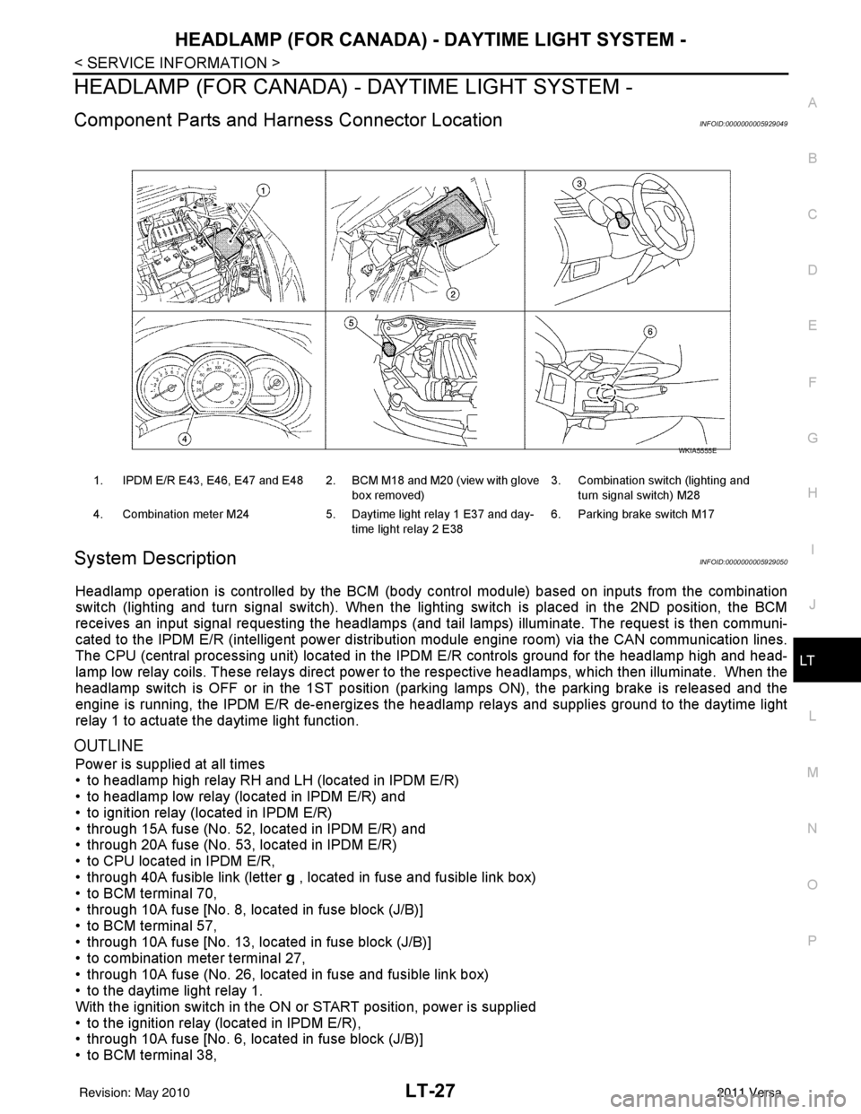
Component Parts and Harness Connector LocationINFOID:0000000005929049
System DescriptionINFOID:0000000005929050
Headlamp operation is controlled by the BCM (body c ontrol module) based on inputs from the combination
switch (lighting and turn signal switch). When the light ing switch is placed in the 2ND position, the BCM
receives an input signal requesting the headlamps (and ta il lamps) illuminate. The request is then communi-
cated to the IPDM E/R (intelligent power distribution module engine room) via the CAN communication lines.
The CPU (central processing unit) located in t he IPDM E/R controls ground for the headlamp high and head-
lamp low relay coils. These relays direct power to the respective headlamps, which then illuminate. When the
headlamp switch is OFF or in the 1ST position (parking lamps ON), the parking brake is released and the
engine is running, the IPDM E/R de-energizes the headlamp relays and supplies ground to the daytime light
relay 1 to actuate the daytime light function.
OUTLINE
Power is supplied at all times
• to headlamp high relay RH and LH (located in IPDM E/R)
• to headlamp low relay (located in IPDM E/R) and
• to ignition relay (located in IPDM E/R)
• through 15A fuse (No. 52, located in IPDM E/R) and
• through 20A fuse (No. 53, located in IPDM E/R)
• to CPU located in IPDM E/R,
• through 40A fusible link (letter g , located in fuse and fusible link box)
• to BCM terminal 70,
• through 10A fuse [No. 8, located in fuse block (J/B)]
• to BCM terminal 57,
• through 10A fuse [No. 13, located in fuse block (J/B)]
• to combination meter terminal 27,
• through 10A fuse (No. 26, located in fuse and fusible link box)
• to the daytime light relay 1.
With the ignition switch in the ON or START position, power is supplied
• to the ignition relay (located in IPDM E/R),
• through 10A fuse [No. 6, located in fuse block (J/B)]
• to BCM terminal 38,
1. IPDM E/R E43, E46, E47 and E48 2. BCM M18 and M20 (view with glove
box removed)3. Combination switch (lighting and
turn signal switch) M28
4. Combination meter M24 5. Daytime light relay 1 E37 and day-
time light relay 2 E38 6. Parking brake switch M17
WKIA5555E
Revision: May 2010
2011 Versa