2011 NISSAN LATIO Air cleaner
[x] Cancel search: Air cleanerPage 35 of 3787
AT-18
< SERVICE INFORMATION >
A/T FLUID
5. Run engine at idle speed for 5 minutes.
6. Check A/T fluid level and condition. Refer to AT-17, "
Checking A/T Fluid".
A/T Fluid Cooler CleaningINFOID:0000000005928072
Whenever the A/T is repaired, overhauled, or replaced, the A/T fluid cooler mounted in the radiator must be
inspected and cleaned.
Metal debris and friction material, if present, can becom e trapped in the A/T fluid cooler. This debris can con-
taminate the newly serviced A/T or, in severe cases, can bloc k or restrict the flow of A/T fluid. In either case,
malfunction of the newly serviced A/T may result.
Debris, if present, may build up as A/T fluid enters the c ooler inlet. It will be necessary to back flush the cooler
through the cooler outlet in order to flush out any built up debris.
A/T FLUID COOLER CLEANING PROCEDURE
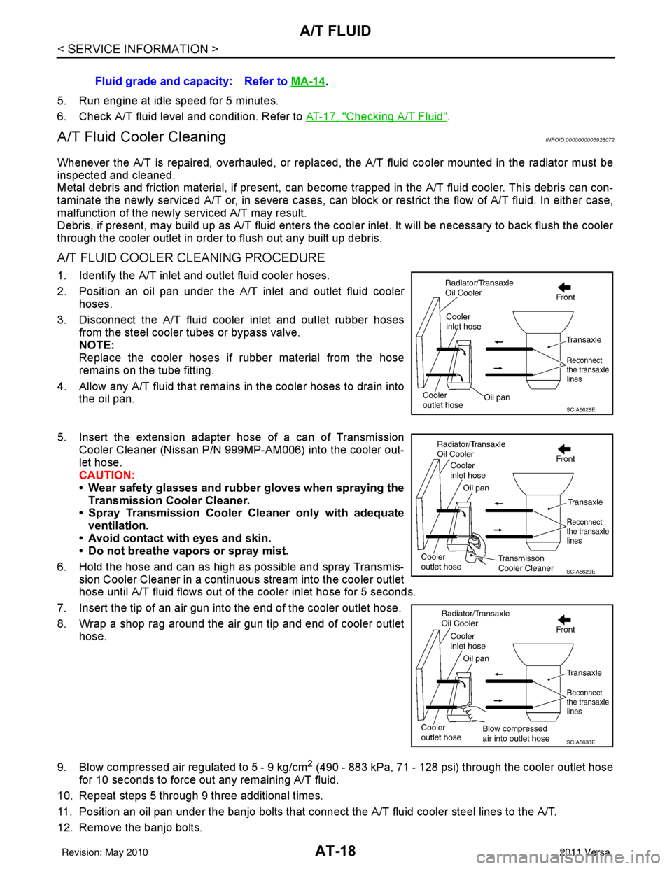
1. Identify the A/T inlet and outlet fluid cooler hoses.
2. Position an oil pan under the A/T inlet and outlet fluid cooler hoses.
3. Disconnect the A/T fluid cooler inlet and outlet rubber hoses from the steel cooler tubes or bypass valve.
NOTE:
Replace the cooler hoses if rubber material from the hose
remains on the tube fitting.
4. Allow any A/T fluid that remains in the cooler hoses to drain into the oil pan.
5. Insert the extension adapter hose of a can of Transmission
Cooler Cleaner (Nissan P/N 999MP-AM006) into the cooler out-
let hose.
CAUTION:
• Wear safety glasses and rubber gloves when spraying the Transmission Cooler Cleaner.
• Spray Transmission Cooler Cleaner only with adequate
ventilation.
• Avoid contact with eyes and skin.
• Do not breathe vapors or spray mist.
6. Hold the hose and can as high as possible and spray Transmis- sion Cooler Cleaner in a continuous stream into the cooler outlet
hose until A/T fluid flows out of t he cooler inlet hose for 5 seconds.
7. Insert the tip of an air gun into the end of the cooler outlet hose.
8. Wrap a shop rag around the air gun tip and end of cooler outlet hose.
9. Blow compressed air regulated to 5 - 9 kg/cm
2 (490 - 883 kPa, 71 - 128 psi) through the cooler outlet hose
for 10 seconds to force out any remaining A/T fluid.
10. Repeat steps 5 through 9 three additional times.
11. Position an oil pan under the banjo bolts that connec t the A/T fluid cooler steel lines to the A/T.
12. Remove the banjo bolts. Fluid grade and capacity: Refer to
MA-14
.
SCIA5628E
SCIA5629E
SCIA5630E
Revision: May 2010 2011 Versa
Page 36 of 3787
A/T FLUIDAT-19
< SERVICE INFORMATION >
DE
F
G H
I
J
K L
M A
B
AT
N
O P
13. Flush each steel line from the cooler side back toward the A/T by spraying Transmission Cooler Cleaner in a continuous stream for 5 seconds.
14. Blow compressed air regulated to 5 - 9 kg/cm
2 (490 - 883 kPa, 71 - 128 psi) through each steel line from
the cooler side back toward the A/T for 10 seconds to force out any remaining A/T fluid.
15. Ensure all debris is removed from the steel cooler lines.
16. Ensure all debris is removed from the banjo bolts and fittings.
17. Perform "A/T FLUID COOL ER DIAGNOSIS PROCEDURE".
A/T FLUID COOLER DIAGNOSIS PROCEDURE
NOTE:
Insufficient cleaning of the cooler inlet hose exte rior may lead to inaccurate debris identification.
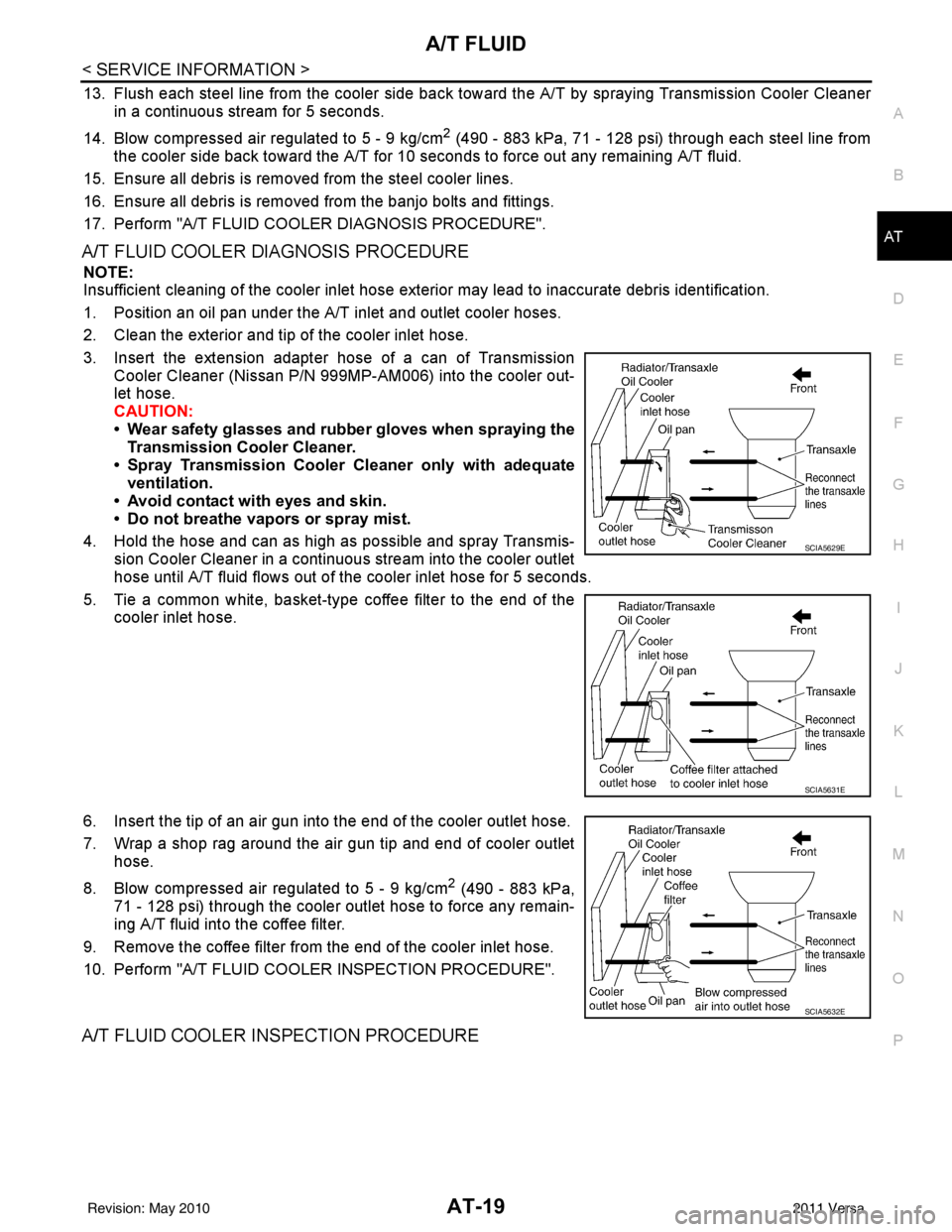
1. Position an oil pan under the A/T inlet and outlet cooler hoses.
2. Clean the exterior and tip of the cooler inlet hose.
3. Insert the extension adapter hose of a can of Transmission Cooler Cleaner (Nissan P/N 999MP-AM006) into the cooler out-
let hose.
CAUTION:
• Wear safety glasses and rubber gloves when spraying the
Transmission Cooler Cleaner.
• Spray Transmission Cooler Cleaner only with adequate
ventilation.
• Avoid contact with eyes and skin.
• Do not breathe vapors or spray mist.
4. Hold the hose and can as high as possible and spray Transmis- sion Cooler Cleaner in a continuous stream into the cooler outlet
hose until A/T fluid flows out of t he cooler inlet hose for 5 seconds.
5. Tie a common white, basket-type coffee filter to the end of the cooler inlet hose.
6. Insert the tip of an air gun into the end of the cooler outlet hose.
7. Wrap a shop rag around the air gun tip and end of cooler outlet hose.
8. Blow compressed air regulated to 5 - 9 kg/cm
2 (490 - 883 kPa,
71 - 128 psi) through the cooler outlet hose to force any remain-
ing A/T fluid into the coffee filter.
9. Remove the coffee filter from the end of the cooler inlet hose.
10. Perform "A/T FLUID COOL ER INSPECTION PROCEDURE".
A/T FLUID COOLER INSPECTION PROCEDURE
SCIA5629E
SCIA5631E
SCIA5632E
Revision: May 2010 2011 Versa
Page 244 of 3787

ON-VEHICLE SERVICEAT-227
< SERVICE INFORMATION >
DE
F
G H
I
J
K L
M A
B
AT
N
O P
2. Set shift selector and manual shaft (1) in “N” position.
3. Remove shift selector control cable from manual shaft (1). Refer to AT-213, "
A/T Shift Selector Removal and Installation".
4. Loosen transmission range switch bolts. :Bolt
5. Insert the pin (3) [4 mm (0.16 in) dia.] straight into manual shaft (1) adjustment hole.
6. Rotate transmission range switch (2) until the pin (3) can also be inserted straight into hole in transmission range switch (2).
7. Tighten transmission range switch bolts to the specified torque. Refer to "COMPONENTS".
8. Remove the pin (3) from adjustment hole after adjusting transmission range switch (2).
9. Install the shift selector control cable. Refer to AT-213, "
A/T Shift Selector Removal and Installation".
10. Adjust and check A/T position. Refer to AT-217, "
Adjustment of A/T Position" and AT-217, "Checking of A/
T Position".
11. Check continuity of transmiss ion range switch (2). Refer to AT-175, "
Component Inspection".
12. Install the air duct (inlet). Refer to EM-135
.
Output Speed SensorINFOID:0000000005928280
COMPONENTS
REMOVAL AND INSTALLATION
Removal
1. Disconnect the battery negative terminal.
2. Remove air duct (inlet), air duct and air cleaner case. Refer to EM-135, "
Component".
WCIA0654E
1. A/T2. Output speed sensor3. Gusset
AWDIA0658ZZ
Revision: May 2010 2011 Versa
Page 249 of 3787
AT-232
< SERVICE INFORMATION >
AIR BREATHER HOSE
AIR BREATHER HOSE
Removal and InstallationINFOID:0000000005928283
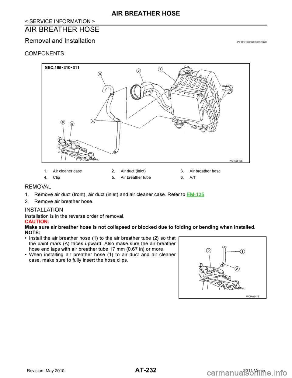
COMPONENTS
REMOVAL
1. Remove air duct (front), air duct (inlet) and air cleaner case. Refer to EM-135.
2. Remove air breather hose.
INSTALLATION
Installation is in the reverse order of removal.
CAUTION:
Make sure air breather hose is not collapsed or bl ocked due to folding or bending when installed.
NOTE:
• Install the air breather hose (1) to the air breather tube (2) so that
the paint mark (A) faces upward. Also make sure the air breather
hose end laps with air breather tube 17 mm (0.67 in) or more.
• When installing air breather hose (1) to air duct and air cleaner
case, make sure to fully insert the hose clips.
1. Air cleaner case 2. Air duct (inlet) 3. Air breather hose
4. Clip 5. Air breather tube 6. A/T
WCIA0642E
WCIA0641E
Revision: May 2010 2011 Versa
Page 862 of 3787
BRAKE MASTER CYLINDERBR-15
< SERVICE INFORMATION >
C
DE
G H
I
J
K L
M A
B
BR
N
O P
BRAKE MASTER CYLINDER
On-Board InspectionINFOID:0000000005928402
LEAK INSPECTION
• Check for leaks around the master cylinder installation surface, the reservoir tank installation surface, and all the brake tube connections.
Removal and InstallationINFOID:0000000005928403
CAUTION:
Be careful not to splash brake fluid on painted areas; it may cause paint damage. If brake fluid is
splashed on painted areas, immediately wipe th em with cloth and wash it away with water.
REMOVAL
1. Drain the brake fluid. Refer to BR-9, "Drain and Refill".
2. Remove the battery. Refer to SC-7, "
Removal and Installation".
3. Remove the air duct. Refer to EM-135, "
Removal and Installation".
4. Remove the air cleaner. Refer to EM-135, "
Removal and Installation".
5. Disconnect the brake fluid level switch harness connector.
6. Disconnect the clutch hose from the reservoir tank, if equipped.
7. Remove the brake tube from master cylinder using a suitable tool.
8. Remove the master cylinder assembly nuts, and remove master cylinder assembly.
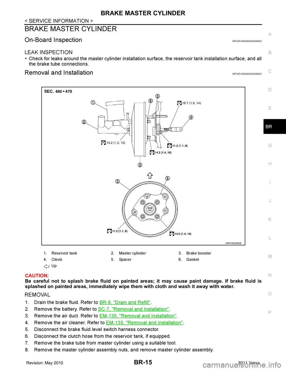
1. Reservoir tank 2. Master cylinder 3. Brake booster
4. Clevis 5. Spacer 6. Gasket
Up
AWFIA0530GB
Revision: May 2010 2011 Versa
Page 863 of 3787
BR-16
< SERVICE INFORMATION >
BRAKE MASTER CYLINDER
INSTALLATION
CAUTION:
• Refill using recommended brake fluid. Refer to MA-14, "
Fluids and Lubricants".
• Never reuse drained brake fluid.
• Check if the rod of primary piston has dust or scratches.
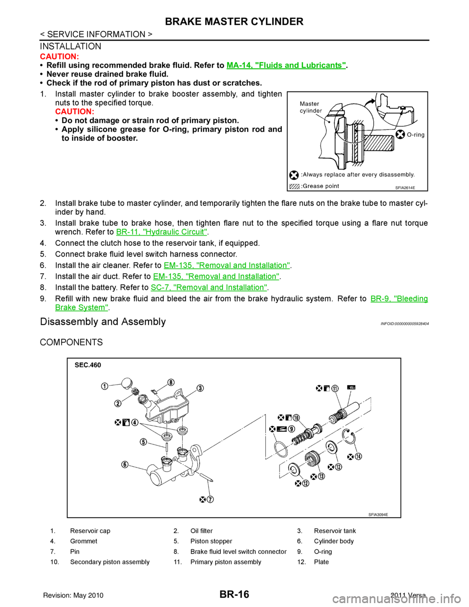
1. Install master cylinder to brake booster assembly, and tighten nuts to the specified torque.
CAUTION:
• Do not damage or strain rod of primary piston.
• Apply silicone grease for O-ring, primary piston rod andto inside of booster.
2. Install brake tube to master cylinder, and temporarily tighten the flare nuts on the brake tube to master cyl- inder by hand.
3. Install brake tube to brake hose, then tighten flare nut to the specified torque using a flare nut torque
wrench. Refer to BR-11, "
Hydraulic Circuit".
4. Connect the clutch hose to the reservoir tank, if equipped.
5. Connect brake fluid level switch harness connector.
6. Install the air cleaner. Refer to EM-135, "
Removal and Installation".
7. Install the air duct. Refer to EM-135, "
Removal and Installation".
8. Install the battery. Refer to SC-7, "
Removal and Installation".
9. Refill with new brake fluid and bleed the air from the brake hydraulic system. Refer toBR-9, "
Bleeding
Brake System".
Disassembly and AssemblyINFOID:0000000005928404
COMPONENTS
SFIA2614E
1. Reservoir cap2. Oil filter 3. Reservoir tank
4. Grommet 5. Piston stopper 6. Cylinder body
7. Pin 8. Brake fluid level switch connector 9. O-ring
10. Secondary piston assembly 11. Primary piston assembly 12. Plate
SFIA3094E
Revision: May 2010 2011 Versa
Page 992 of 3787
CLUTCH MASTER CYLINDERCL-11
< SERVICE INFORMATION >
DE
F
G H
I
J
K L
M A
B
CL
N
O P
CLUTCH MASTER CYLINDER
Removal and InstallationINFOID:0000000005928997
REMOVAL
1. Remove the battery, battery tray and brackets. Refer to SC-5.
2. Remove the air cleaner and air duct. Refer to EM-25, "
Removal and Installation" (HR16DE models), EM-
135, "Removal and Installation" (MR18DE models).
3. Use one of the following methods to remove hose from master cylinder.
• Drain clutch fluid from reservoir tank and remove hose.
• Remove hose from master cylinder. Immediately plug hose and reservoir tank to prevent clutch fluid
from dripping.
CAUTION:
Do not spill clutch fluid onto painted surfaces. If it spills, wipe up immediately and wash the
affected area with water.
4. Remove master cylinder rod end from clutch pedal assembly.
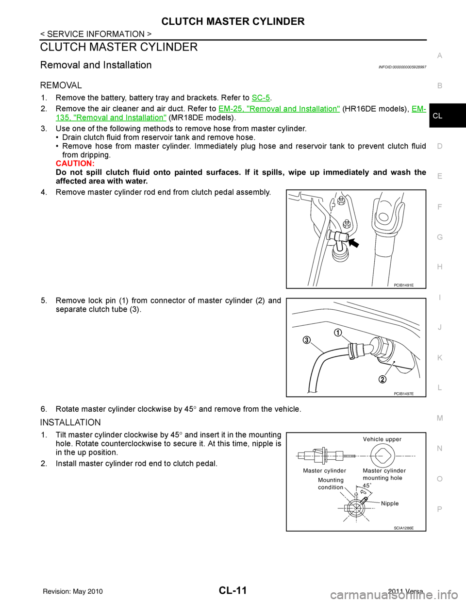
5. Remove lock pin (1) from connector of master cylinder (2) and separate clutch tube (3).
6. Rotate master cylinder clockwise by 45 ° and remove from the vehicle.
INSTALLATION
1. Tilt master cylinder clockwise by 45° and insert it in the mounting
hole. Rotate counterclockwise to secure it. At this time, nipple is
in the up position.
2. Install master cylinder rod end to clutch pedal.
PCIB1491E
PCIB1497E
SCIA1286E
Revision: May 2010 2011 Versa
Page 993 of 3787
CL-12
< SERVICE INFORMATION >
CLUTCH MASTER CYLINDER
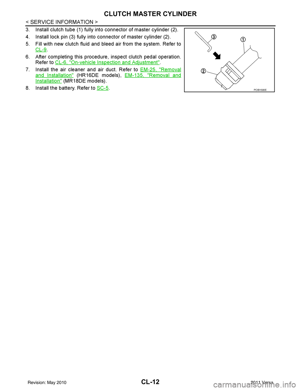
3. Install clutch tube (1) fully into connector of master cylinder (2).
4. Install lock pin (3) fully into connector of master cylinder (2).
5. Fill with new clutch fluid and bleed air from the system. Refer toCL-9
.
6. After completing this procedure, inspect clutch pedal operation. Refer to CL-6, "
On-vehicle Inspection and Adjustment".
7. Install the air cleaner and air duct. Refer to EM-25, "
Removal
and Installation" (HR16DE models), EM-135, "Removal and
Installation" (MR18DE models).
8. Install the battery. Refer to SC-5
.PCIB1500E
Revision: May 2010 2011 Versa