2011 NISSAN LATIO window
[x] Cancel search: windowPage 3475 of 3787
HARNESSPG-55
< SERVICE INFORMATION >
C
DE
F
G H
I
J
L
M A
B
PG
N
O P
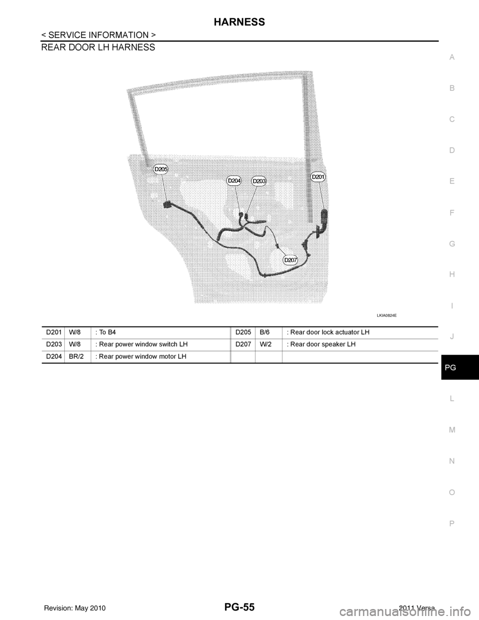
REAR DOOR LH HARNESS
LKIA0824E
D201 W/8 : To B4 D205 B/6 : Rear door lock actuator LH
D203 W/8 : Rear power window switch LH D207 W/2 : Rear door speaker LH
D204 BR/2 : Rear power window motor LH
Revision: May 2010 2011 Versa
Page 3476 of 3787
PG-56
< SERVICE INFORMATION >
HARNESS
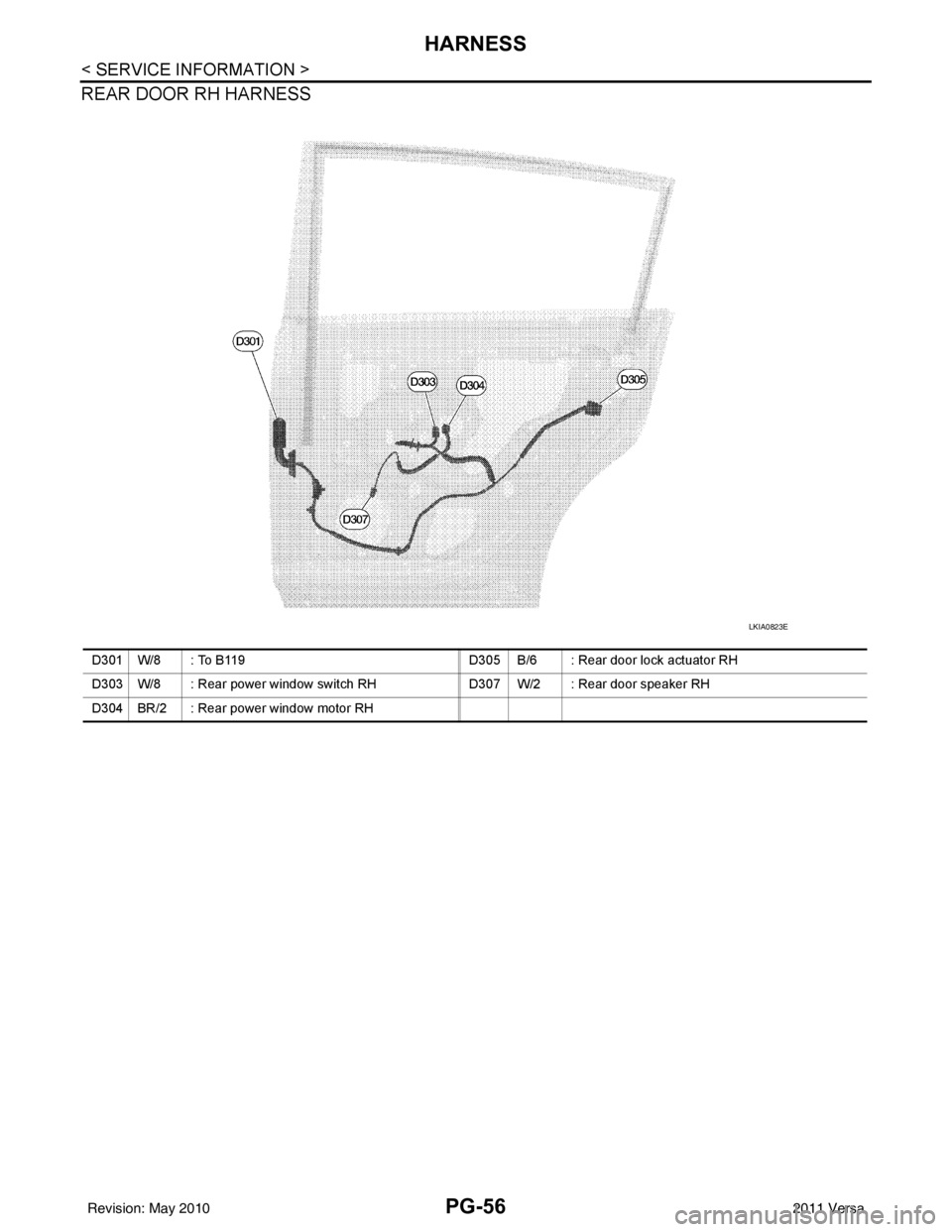
REAR DOOR RH HARNESS
LKIA0823E
D301 W/8 : To B119D305 B/6 : Rear door lock actuator RH
D303 W/8 : Rear power window switch RH D307 W/2 : Rear door speaker RH
D304 BR/2 : Rear power window motor RH
Revision: May 2010 2011 Versa
Page 3477 of 3787
HARNESSPG-57
< SERVICE INFORMATION >
C
DE
F
G H
I
J
L
M A
B
PG
N
O P
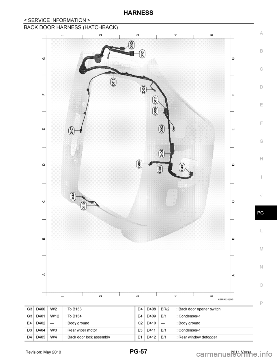
BACK DOOR HARNESS (HATCHBACK)
ABMIA2325GB
G3 D400 W/2 : To B133 D4 D408 BR/2 : Back door opener switch
G3 D401 W/12 : To B134 E4 D409 B/1 : Condenser-1
E4 D402 — : Body ground C2 D410 — : Body ground
D3 D404 W/3 : Rear wiper mo torE3 D411 B/1 : Condenser-1
D4 D405 W/4 : Back door lock assembly E1 D412 B/1 : Rear window defogger
Revision: May 2010 2011 Versa
Page 3478 of 3787

PG-58
< SERVICE INFORMATION >
HARNESS
Wiring Diagram Codes (Cell Codes)
INFOID:0000000005928356
Use the chart below to find out what each wiring diagram code stands for.
Refer to the wiring diagram code in the alphabetical index to find the location (page number) of each wiring
diagram.
D4 D406 W/2 : Back door request switch C2 D413 B/1 : Rear window defogger (-)
E2 D407 W/2 : High mounted stop lamp
Code Section Wiring Diagram Name
ABS BRC Anti-lock Brake System
A/C,M MTC Manual Air Conditioner
APPS1 EC Accelerator Pedal Position Sensor
A/F EC Air Fuel Ratio Sensor 1
A/FH EC Air Fuel Ratio Sensor 1 Heater
APPS2 EC Accelerator Pedal Position Sensor
APPS3 EC Accelerator Pedal Position Sensor
ASC/BS EC ASCD Brake Switch
ASC/SW EC ASCD Steering Switch
ASCBOF EC ASCD Brake Switch
ASCIND EC ASCD Indicator
AT/IND DI A/T Indicator Lamp
AUDIO AV Audio
BACK/L LT Back-up Lamp
BA/FTS AT A/T Fluid Temperature Sensor and TCM Power Supply
B/DOOR BL Back Door Opener
BRK/SW EC Brake Switch
CAN AT CAN Communication Line
CAN CVT CAN Communication Line
CAN EC CAN Communication Line
CAN LAN CAN System
CHARGE SC Charging System
CHIME DI Warning Chime
COOL/F EC Cooling Fan Control
COMBSW LT Combination Switch
COMM AV Audio Visual Communication System
CVTIND DI CVT Indicator Lamp
D/LOCK BL Power Door Lock
DEF GW Rear Window Defogger
DTRL LT Headlamp - With Daytime Light System
ECTS EC Engine Coolant Temperature Sensor
ENGSS AT Engine Speed Signal
EPS STC Electronic Controlled Power Steering
ETC1 EC Electric Throttle Control Function
ETC2 EC Throttle Control Motor Relay
ETC3 EC Throttle Control Motor
F/FOG LT Front Fog Lamp
F/PUMP EC Fuel Pump
FTS AT A/T Fluid Temperature Sensor
FTS CVT CVT Fluid Temperature Sensor Circuit
FTTS EC Fuel Tank Temperature Sensor
FUEL EC Fuel Ignition System Function
HEATER MTC Heater System
Revision: May 2010 2011 Versa
Page 3480 of 3787

PG-60
< SERVICE INFORMATION >
HARNESS
TCVAT Torque Converter Clutch Solenoid Valve
TCV CVT Torque Converter Clutch Solenoid Valve
T/LID BL Trunk Lid Opener
T/WARN WT Low Tire Pressure Warning System
TAIL/L LT Parking, License and Tail Lamps
TPS1 EC Throttle Position Sensor
TPS2 EC Throttle Position Sensor
TPS3 EC Throttle Position Sensor
TR/SW AT Transmission Range Switch
TR/SW CVT Transmission Range Switch
TURN LT Turn Signal and Hazard Warning Lamps
VDC BRC Vehicle Dynamic Control System
VEHSEC BL Vehicle Security (Theft Warning) System
VENT/V EC EVAP Canister Vent Control Valve
VSSA/T AT Vehicle Speed Sensor A/T (Input Speed Sensor)
VSSMTR AT Vehicle Speed Sensor MTR
WARN DI Warning Lamps
WINDOW GW Power Window
WIP/R WW Rear Wiper and Washer
WIPER WW Front Wiper and Washer
Revision: May 2010 2011 Versa
Page 3540 of 3787
TROUBLE DIAGNOSISRF-17
< FUNCTION DIAGNOSIS >
C
DE
F
G H
J
K L
M A
B
RF
N
O P
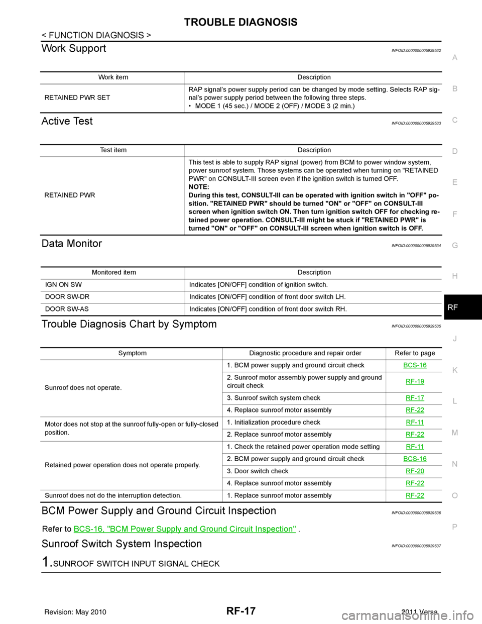
Work SupportINFOID:0000000005929532
Active TestINFOID:0000000005929533
Data MonitorINFOID:0000000005929534
Trouble Diagnosis Chart by SymptomINFOID:0000000005929535
BCM Power Supply and Gr ound Circuit InspectionINFOID:0000000005929536
Refer to BCS-16, "BCM Power Supply and Ground Circuit Inspection" .
Sunroof Switch System InspectionINFOID:0000000005929537
1.SUNROOF SWITCH INPUT SIGNAL CHECK
Work item Description
RETAINED PWR SET RAP signal’s power supply period can be changed by mode setting. Selects RAP sig-
nal’s power supply period between the following three steps.
• MODE 1 (45 sec.) / MODE 2 (OFF) / MODE 3 (2 min.)
Test item
Description
RETAINED PWR This test is able to supply RAP signal (power) from BCM to power window system,
power sunroof system. Those systems can be operated when turning on "RETAINED
PWR" on CONSULT-III screen even if the ignition switch is turned OFF.
NOTE:
During this test, CONSULT-III can be operated with ignition switch in "OFF" po-
sition. "RETAINED PWR" should be turned "ON" or "OFF" on CONSULT-III
screen when ignition switch ON. Then turn ignition switch OFF for checking re-
tained power operation. CONSULT-III might be stuck if "RETAINED PWR" is
turned "ON" or "OFF" on CONSULT-III screen when ignition switch is OFF.
Monitored item
Description
IGN ON SW Indicates [ON/OFF] condition of ignition switch.
DOOR SW-DR Indicates [ON/OFF] condition of front door switch LH.
DOOR SW-AS Indicates [ON/OFF] condition of front door switch RH.
SymptomDiagnostic procedure and repair order Refer to page
Sunroof does not operate. 1. BCM power supply and ground circuit check
BCS-16
2. Sunroof motor assembly power supply and ground
circuit check RF-19
3. Sunroof switch system check
RF-17
4. Replace sunroof motor assemblyRF-22
Motor does not stop at the sunroof fully-open or fully-closed
position. 1. Initialization procedure check
RF-11
2. Replace sunroof motor assemblyRF-22
Retained power operation does not operate properly. 1. Check the retained power operation mode setting
RF-112. BCM power supply and ground circuit checkBCS-16
3. Door switch check RF-20
4. Replace sunroof motor assemblyRF-22
Sunroof does not do the interruption detection. 1. Replace sunroof motor assemblyRF-22
Revision: May 2010 2011 Versa
Page 3586 of 3787
SC-8
< SERVICE INFORMATION >
BATTERY
INSTALLATION (All except MR18DE with CVT)
Installation is in the reverse order of removal.
CAUTION:
When connecting, connect the battery positive terminal first.
Reset electronic systems as necessary. Refer to SC-8, "
Required Procedure After Battery Disconnection".
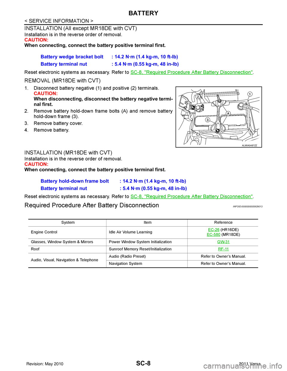
REMOVAL (MR18DE with CVT)
1. Disconnect battery negative (1) and positive (2) terminals.
CAUTION:
When disconnecting, disconnect the battery negative termi-
nal first.
2. Remove battery hold-down frame bolts (A) and remove battery hold-down frame (3).
3. Remove battery cover.
4. Remove battery.
INSTALLATION (MR18DE with CVT)
Installation is in the reverse order of removal.
CAUTION:
When connecting, connect the battery positive terminal first.
Reset electronic systems as necessary. Refer to SC-8, "
Required Procedure After Battery Disconnection".
Required Procedure After Battery DisconnectionINFOID:0000000005929013
Battery wedge bracket bolt : 14.2 N·m (1.4 kg-m, 10 ft-lb)
Battery terminal nut : 5.4 N·m (0.55 kg-m, 48 in-lb)
ALMIA0487ZZ
Battery hold-down frame bolt : 14.2 N·m (1.4 kg-m, 10 ft-lb)
Battery terminal nut : 5.4 N·m (0.55 kg-m, 48 in-lb)
System ItemReference
Engine Control Idle Air Volume Learning EC-26
(HR16DE)
EC-580
(MR18DE)
Glasses, Window System & Mirrors Power Window System Initialization GW-31
RoofSunroof Memory Reset/Initialization RF-11
Audio, Visual, Navigation & TelephoneAudio (Radio Preset)
Refer to Owner’s Manual.
Navigation System Refer to Owner’s Manual.
Revision: May 2010 2011 Versa
Page 3774 of 3787

WW-28
< SERVICE INFORMATION >
REAR WIPER AND WASHER SYSTEM
• to rear wiper motor terminal 3
• through grounds B117, B132 and D402.
With power and ground supplied, the rear wiper motor operates.
INTERMITTENT OPERATION
The rear wiper motor operates the wiper arm at low speed approximately every 7 seconds.
When the combination switch (wiper switch) is in the r ear wiper INT position, the BCM detects a rear wiper INT
request through the combination switch (wiper switch) reading function.
When BCM operates rear wiper motor, power is supplied
• through BCM terminal 55
• to rear wiper motor terminal 1.
Ground is supplied
• to rear wiper motor terminal 3
• through grounds B117, B132 and D402.
With power and ground supplied, the rear wiper operates in intermittent mode.
AUTO STOP OPERATION
When the rear wiper arm is not located at the base of the rear window, and the rear combination switch (wiper
switch) is turned OFF, the rear wiper motor will continue to operate until the rear wiper arm is at the base of the
rear window. When the rear wiper arm reaches the bas e, rear wiper motor terminals 2 and 1 are connected.
Ground is supplied
• to BCM terminal 44
• through rear wiper motor terminal 2, and
• through rear wiper motor terminal 3, and
• through grounds B117, B132 and D402.
REAR WASHER OPERATION
When the ignition switch is in the ON or START positi on, and the front and rear washer switches are OFF, the
front and rear washer motor is supplied power
• through 15A fuse [No. 4, located in the fuse block (J/B)]
• to combination switch (wiper switch) terminal 14
• through combination switch (wiper switch) terminal 11
• to front and rear washer motor terminal 2.
When the rear combination switch (wiper switch) is in rear washer position, the BCM detects a rear washer
signal by BCM combination switch (wiper switch) readi ng function. Combination switch (wiper switch) ground
is supplied
• to front and rear washer motor terminal 1
• through combination switch (wiper switch) terminal 13, and
• through combination switch (wiper switch) terminal 12
• through grounds M57 and M61.
With ground supplied, the front and rear washer motor is operated in the rear direction.
When the BCM detects that the rear washer motor has operated for 0.4 seconds or longer, BCM operates the
rear wiper motor.
When the BCM detects that the rear washer switch is in OFF, the rear wiper motor cycles approximately 3
times and then stops.
If the rear washer is operated with the rear combinati on switch (wiper switch) in the INT position, normal rear
wiper operation will take over. Once the rear washer switch is released the rear wiper will return to INT opera-
tion.
BCM Combination Switch (Wiper Switch) Reading Function
Refer to BCS-4, "System Description" .
Revision: May 2010 2011 Versa