2011 NISSAN LATIO low oil pressure
[x] Cancel search: low oil pressurePage 2874 of 3787
![NISSAN LATIO 2011 Service Repair Manual LAN-28
< SERVICE INFORMATION >[CAN]
CAN COMMUNICATION SYSTEM
*1: A/T models
*2: CVT models
*3: Models with VDC
*4: Models for Canada
*5: Models for USA
*6: Models without ABS
NOTE:
CAN data of the air NISSAN LATIO 2011 Service Repair Manual LAN-28
< SERVICE INFORMATION >[CAN]
CAN COMMUNICATION SYSTEM
*1: A/T models
*2: CVT models
*3: Models with VDC
*4: Models for Canada
*5: Models for USA
*6: Models without ABS
NOTE:
CAN data of the air](/manual-img/5/57357/w960_57357-2873.png)
LAN-28
< SERVICE INFORMATION >[CAN]
CAN COMMUNICATION SYSTEM
*1: A/T models
*2: CVT models
*3: Models with VDC
*4: Models for Canada
*5: Models for USA
*6: Models without ABS
NOTE:
CAN data of the air bag diagnosis sensor unit is not used by usual service work, thus it is omitted.
KEY warning lamp signal
T R
LOCK warning lamp signal T R
Panic alarm request signal RT
Fuel level sensor signal RT
Overdrive control switch signal TR R
Parking brake switch signal
*3TR
Stop lamp switch signal T R R
Vehicle speed signal RRRR T
RRR T R
R
*6T*6
Steering angle sensor signal*3TR
ABS warning lamp signal RT
Brake warning lamp signal RT
SLIP indicator lamp signal
*3RT
VDC OFF indicator lamp signal
*3RT
VDC warning lamp signal
*3RT
A/T check indicator signal RT
A/T self-diagnosis signal R T
Input speed signal R T
OD OFF indicator signal RT
Output shaft revolution signal R T T
Shift position indicator signal R
R
*3TT
CVT self-diagnosis signal R T
Input shaft revolution signal R T
OD OFF indicator signal RT
Front wiper stop position signal R T
High beam status signal R T
Low beam status signal R T
Oil pressure switch signal R RR T
Rear window defogger control signal R T
Signal name/Connecting unit
ECM
BCM
EPS
I-KEY M&A
STRG ABS
TCM
*1
TCM
*2
IPDM-E
Revision: May 2010 2011 Versa
Page 3045 of 3787

HEADLAMP (FOR USA)LT-13
< SERVICE INFORMATION >
C
DE
F
G H
I
J
L
M A
B
LT
N
O P
WORK SUPPORT
Display Item List
CONSULT-III Function (IPDM E/R)INFOID:0000000006227567
CONSULT-III can display each diagnostic item using the diagnostic test modes shown following.
SELF-DIAGNOSTIC RESULTS
Display Item List
Blower fan switch sig-
nal
Air conditioner switch
signal AIR CONDITION-
ER
××
Intelligent Key INTELLIGENT
KEY ×
Combination switch COMB SW ×
NVIS (NATS) IMMU ××
Interior lamp battery
saver BATTERY SAV-
ER
××
×
Back door/Trunk TRUNK ××
Theft alarm THEFT ALARM×× ×
Retained accessory
power control RETAINED PWR
×× ×
Oil pressure switch SIGNAL BUFFER ××
Low tire pressure moni-
tor AIR PRESSURE
MONITOR
××
× ×
Panic alarm PANIC ALARM ×
System and item
CONSULT-III
display Diagnostic test mode (Inspection by part)
WORK
SUPPORT SELF
DIAGNOS-
TIC RE-SULT CAN DIAG
SUPPORT MNTR DATA
MONITOR ECU
IDENTI-
FICA-TION AC-
TIVE
TEST CON-
FIGU-
RATION
Item Description
RESET SETTING VALUE Return a value set with WORK SUPPORT of each system to a default value in factory shipment.
IPDM E/R diagnostic Mode Description
SELF-DIAG RESULTS Displays IPDM E/R self-diagnosis results. DATA MONITOR Displays IPDM E/R input/output data in real time.
CAN DIAG SUPPORT MNTR The result of transmit/receive diagnosis of CAN communication can be read. ACTIVE TEST Operation of electrical loads can be checked by sending drive signal to them.
Revision: May 2010 2011 Versa
Page 3046 of 3787

LT-14
< SERVICE INFORMATION >
HEADLAMP (FOR USA)
x: Applicable
NOTE:
The details for display of the period are as follows:
• CRNT: Error currently detected with IPDM E/R.
• PAST: Error detected in the past and placed in IPDM E/R memory.
DATA MONITOR
All Signals, Main Signals, Selection From Menu
Display itemsCONSULT-
III display code Malfunction detection TIME
Possible causes
CRNT PAST
NO DTC IS DETECTED.
FURTHER TESTING
MAY BE REQUIRED. —————
CAN COMM CIRC U1000 • If CAN communication reception/transmission
data has a malfunction, or if any of the control
units fail, data reception/transmission cannot be
confirmed.
• When the data in CAN communication is not re-
ceived before the specified time. XX
Any of items listed
below have errors:
• TRANSMIT DIAG
•ECM
• BCM/SEC
IGN RELAY ON —When the ignition switch is not in the ON position,
the ignition relay in the IPDM E/R is ON. XX
Ignition relay (inte-
grated in IPDM E/R)
IGN RELAY OFF —When the ignition switch is not in the ON position,
the ignition relay in the IPDM E/R is OFF. XXIgnition relay (inte-
grated in IPDM E/R)
EEPROM —Malfunction is de
tected with the integrated EEPROM
memory diagnosis. X X IPDM E/R
Item nameCONSULT-III
screen display Display or unit Monitor item selection
Description
ALL
SIGNALS MAIN
SIGNALS SELECTION
FROM MENU
Motor fan request MOTOR FAN
REQ1/2/3/4
X X X Signal status input from ECM
Compressor re-
quest AC COMP REQ ON/OFF
X XX Signal status input from ECM
Parking, license,
and tail lamp re-
quest TAIL & CLR REQ ON/OFF
X XX Signal status input from BCM
Headlamp low
beam request HL LO REQ ON/OFF
X XX Signal status input from BCM
Headlamp high
beam request HL HI REQ ON/OFF
X XX Signal status input from BCM
Front fog request FR FOG REQ ON/OFF X XX Signal status input from BCM
FR wiper request FR WIP REQ STOP/1LO/LO/HI X X X Signal status input from BCM
Wiper auto stop WIP AUTO
STOPACT P/STOP P X X
X Output status of IPDM E/R
Wiper protection WIP PROT OFF/LS/HS/Block X X X Control status of IPDM E/R
Starter request ST RLY REQ ON/OFF XX Status of input signal (*1)
Ignition relay
status IGN RLY ON/OFF
X XXIgnition relay status monitored
with IPDM E/R
Rear defogger re-
quest RR DEF REQ ON/OFF
X XX Signal status input from BCM
Oil pressure
switch OIL P SW OPEN/CLOSE X
XSignal status input from IPDM
E/R
Hood switch HOOD SW (*2) OFF XXSignal status input from IPDM
E/R
Revision: May 2010
2011 Versa
Page 3055 of 3787

HEADLAMP (FOR USA)LT-23
< SERVICE INFORMATION >
C
DE
F
G H
I
J
L
M A
B
LT
N
O P
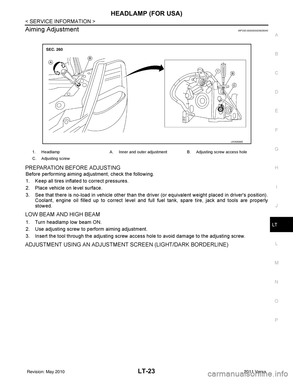
Aiming AdjustmentINFOID:0000000005929045
PREPARATION BEFORE ADJUSTING
Before performing aiming adjustment, check the following.
1. Keep all tires inflated to correct pressures.
2. Place vehicle on level surface.
3. See that there is no-load in vehicle other than the driver (or equivalent weight placed in driver's position). Coolant, engine oil filled up to correct level and full fuel tank, spare tire, jack and tools are properly
stowed.
LOW BEAM AND HIGH BEAM
1. Turn headlamp low beam ON.
2. Use adjusting screw to perform aiming adjustment.
3. Insert the tool through the adjusting screw acce ss hole to avoid damage to the adjusting screw.
ADJUSTMENT USING AN ADJUSTMENT SCREEN (LIGHT/DARK BORDERLINE)
1. HeadlampA. Inner and outer adjustment B. Adjusting screw access hole
C. Adjusting screw
LKIA0930E
Revision: May 2010 2011 Versa
Page 3069 of 3787

HEADLAMP (FOR CANADA) - DAYTIME LIGHT SYSTEM -
LT-37
< SERVICE INFORMATION >
C
D E
F
G H
I
J
L
M A
B
LT
N
O P
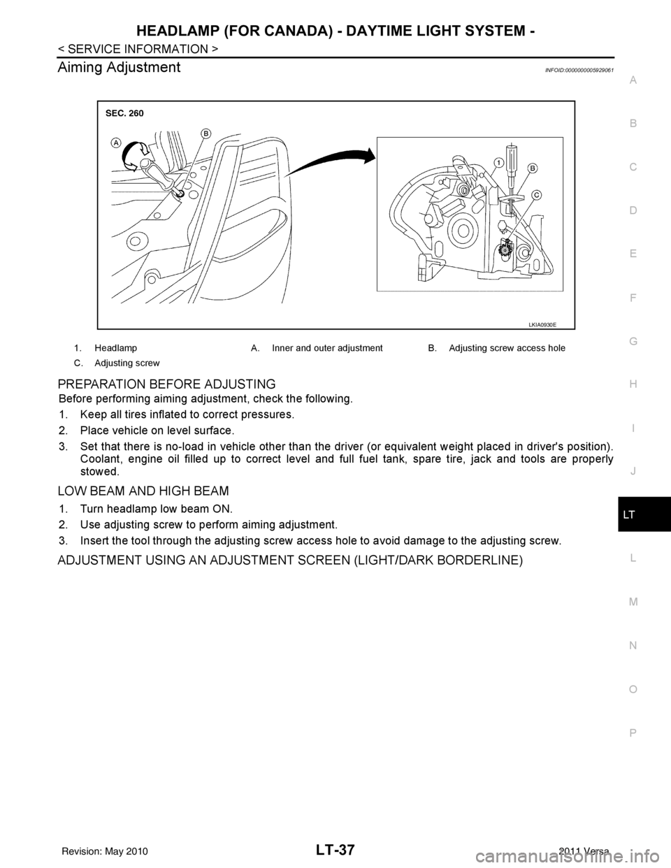
Aiming AdjustmentINFOID:0000000005929061
PREPARATION BEFORE ADJUSTING
Before performing aiming adjustment, check the following.
1. Keep all tires inflated to correct pressures.
2. Place vehicle on level surface.
3. Set that there is no-load in vehicle other than the driv er (or equivalent weight placed in driver's position).
Coolant, engine oil filled up to correct level and full fuel tank, spare tire, jack and tools are properly
stowed.
LOW BEAM AND HIGH BEAM
1. Turn headlamp low beam ON.
2. Use adjusting screw to perform aiming adjustment.
3. Insert the tool through the adjusting screw access hole to avoid damage to the adjusting screw.
ADJUSTMENT USING AN ADJUSTMENT SCREEN (LIGHT/DARK BORDERLINE)
1. Headlamp A. Inner and outer adjustment B. Adjusting screw access hole
C. Adjusting screw
LKIA0930E
Revision: May 2010 2011 Versa
Page 3080 of 3787

LT-48
< SERVICE INFORMATION >
FRONT FOG LAMP
1. Check continuity between front fog lamp harness connector and
ground.
OK or NG
OK >> Replace IPDM E/R. Refer to PG-28, "Removal and
Installation of IPDM E/R" .
NG >> Repair harness or connector.
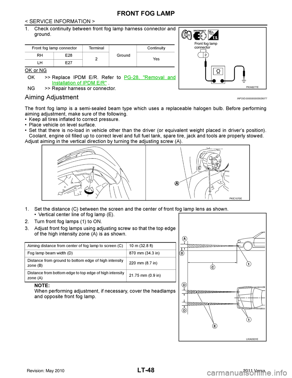
Aiming AdjustmentINFOID:0000000005929077
The front fog lamp is a semi-sealed beam type which uses a replaceable halogen bulb. Before performing
aiming adjustment, make sure of the following.
• Keep all tires inflated to correct pressure.
• Place vehicle on level surface.
• Set that there is no-load in vehicle other than the driv er (or equivalent weight placed in driver’s position).
Coolant, engine oil filled up to correct level and full fuel tank, spare tire, jack and tools are properly stowed.
Adjust aiming in the vertical direct ion by turning the adjusting screw (A).
1. Set the distance (C) between the screen and the center of front fog lamp lens as shown. • Vertical center line of fog lamp (E).
2. Turn front fog lamps (1) to ON.
3. Adjust front fog lamps using adjusting screw so that the top edge of the high intensity zone (A) is as shown.
NOTE:
When performing adjustment, if necessary, cover the headlamps
and opposite front fog lamp.
Front fog lamp connector Terminal
Ground Continuity
RH E28
2Y es
LH E27
PKIA6277E
PKIC1070E
Aiming distance from center of fog lamp to screen (C) 10 m (32.8 ft)
Fog lamp beam width (D) 870 mm (34.3 in)
Distance from ground to bottom edge of high intensity
zone (B) 220 mm (8.7 in)
Distance from bottom edge to top edge of high intensity
zone (A) 21.75 mm (0.9 in)
LKIA0931E
Revision: May 2010
2011 Versa
Page 3136 of 3787

LT-104
< SERVICE INFORMATION >
INTERIOR ROOM LAMP
1 : With remote keyless entry system
2: With Intelligent Key system
WORK SUPPORT
Display Item List
Interior Room Lamp Control Does Not Operate (With Map Lamp)INFOID:0000000005929146
1.CHECK EACH SWITCH
Select "BCM" on CONSULT-III. With "INT LAMP" data monitor, make sure switches listed in display item list
turn ON-OFF linked with switch operation. Refer to BCS-17, "
CONSULT-III Function (BCM)" for switches and
their functions.
OK or NG
OK >> GO TO 2.
NG >> Inspect malfunctioning switch system.
2.ACTIVE TEST
1. Select “BCM” on CONSULT-III. Select “INT LAMP" active test.
2. When room lamp switch is in DOOR position, make sure room lamp operates.
OK or NG
OK >> Replace BCM. Refer to BCS-19, "Removal and Installation of BCM" .
NG >> GO TO 3.
3.CHECK ROOM LAMP INPUT VOLTAGE
Blower fan switch sig-
nal
Air conditioner switch
signal AIR CONDITION-
ER
××
Combination switch COMB SW ×
NVIS (NATS) IMMU ××
Interior lamp battery
saver BATTERY SAV-
ER
××
×
Back door/Trunk TRUNK/BACK
DOOR ××
Theft alarm THEFT ALM×× ×
Retained accessory
power control RETAINED PWR
×× ×
Oil pressure swit ch SIGNAL BUFFER ××
Panic alarm PANIC ALARM ×
Remote keyless entry
system
1MULTI REMOTE
ENTRY ××
×
System and item
CONSULT-III dis-
play Diagnostic test mode (Inspection by part)
WORK
SUPPORT SELF
−
DIAG RE-
SULTS CAN DIAG
SUPPORT
MNTR DATA
MONITOR ECU
PA R T
NUMBER AC-
TIVE
TEST CON-
FIGU-
RATION
Item Description
RESET SETTING VALUE Return a value set with WORK SUPPORT of each system to a default value in factory shipment.
Room lamp should operate.
Revision: May 2010 2011 Versa
Page 3155 of 3787
![NISSAN LATIO 2011 Service Repair Manual ENGINE OILLU-7
< ON-VEHICLE MAINTENANCE > [HR16DE]
C
D
E
F
G H
I
J
K L
M A
LU
NP
O
ON-VEHICLE MAINTENANCE
ENGINE OIL
InspectionINFOID:0000000005928687
ENGINE OIL LEVEL
NOTE:
Park vehicle on a level su NISSAN LATIO 2011 Service Repair Manual ENGINE OILLU-7
< ON-VEHICLE MAINTENANCE > [HR16DE]
C
D
E
F
G H
I
J
K L
M A
LU
NP
O
ON-VEHICLE MAINTENANCE
ENGINE OIL
InspectionINFOID:0000000005928687
ENGINE OIL LEVEL
NOTE:
Park vehicle on a level su](/manual-img/5/57357/w960_57357-3154.png)
ENGINE OILLU-7
< ON-VEHICLE MAINTENANCE > [HR16DE]
C
D
E
F
G H
I
J
K L
M A
LU
NP
O
ON-VEHICLE MAINTENANCE
ENGINE OIL
InspectionINFOID:0000000005928687
ENGINE OIL LEVEL
NOTE:
Park vehicle on a level surface, wait 10 minutes and check the engine oil level.
1. Pull out oil level gauge and wipe it clean.
2. Insert oil level gauge and make sure the engine oil level is within
the range (A) as shown.
3. If it is out of range, adjust it.
ENGINE OIL APPEARANCE
• Check engine oil for white milky appearance or excessive contamination.
• If engine oil becomes white, it is highly probable t hat it is contaminated with engine coolant. Repair or
replace damaged parts.
ENGINE OIL LEAKAGE
Check for engine oil leakage around the following areas:
• Oil pan (upper and lower)
• Oil pan drain plug
• Oil pressure switch
• Oil filter
• Intake valve timing control solenoid valve
• Front cover
• Mating surface between cylinder head and camshaft bracket
• Mating surface between cylinder block and cylinder head
• Mating surface between cylinder head and rocker cover
• Crankshaft oil seals (front and rear)
• Oil filter (for intake valve timing control)
OIL PRESSURE CHECK
WARNING:
• Be careful not to burn yoursel f, as engine oil may be hot.
• For engine oil pressure check the transaxle should be in “Park position” (A/T models) or “Neutral
position” (M/T models), and apply the parking brake securely.
1. Check engine oil level.
2. Remove engine under cover. Refer to EI-15, "
Removal and Installation".
3. Disconnect harness connector at oil pressure switch (2), and remove oil pressure switch (2) from the cylinder block (1) using
suitable tool.
CAUTION:
Never drop or shock oil pressure switch.
JPBIA0554ZZ
PBIC3817E
Revision: May 2010 2011 Versa