2011 NISSAN LATIO low oil pressure
[x] Cancel search: low oil pressurePage 3320 of 3787
MTC-4
< SERVICE INFORMATION >
PRECAUTIONS
5. When the repair work is completed, return the ignition switch to the ″LOCK ″ position before connecting
the battery cables. (At this time, the steering lock mechanism will engage.)
6. Perform a self-diagnosis check of a ll control units using CONSULT-III.
Precaution for Procedure without Cowl Top CoverINFOID:0000000005930825
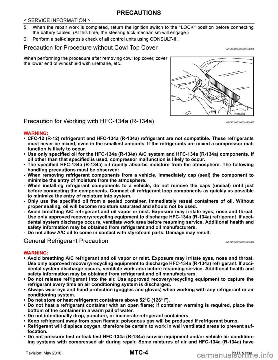
When performing the procedure after removing cowl top cover, cover
the lower end of windshield with urethane, etc.
Precaution for Working with HFC-134a (R-134a)INFOID:0000000005930826
WARNING:
• CFC-12 (R-12) refrigerant and HFC-134a (R-134a) re frigerant are not compatible. These refrigerants
must never be mixed, even in the smallest amounts. If the refrigerants are mixed a compressor mal-
function is likely to occur.
• Use only specified oil for the HFC-134a (R-134a) A/C system and HFC-134a (R-134a) components. If
oil other than that specifi ed is used, compressor malf unction is likely to occur.
• The specified HFC-134a (R-134a) oi l rapidly absorbs moisture from the atmosphere. The following
handling precautions must be observed:
- When removing refrigerant components from a vehicle, immediately cap (seal) the component to
minimize the entry of moisture from the atmosphere.
- When installing refrigerant co mponents to a vehicle, do not remove the caps (unseal) until just
before connecting the components. Connect all refrigerant loop components as quickly as possible
to minimize the entry of moisture into system.
- Only use the specified oil from a sealed container. Immediately reseal containers of oil. Without proper sealing, oil will become moisture saturat ed and should not be used.
- Avoid breathing A/C refrigerant and oil vapor or mist. Exposure may irrita te eyes, nose and throat.
Use only approved recovery/recycling equipment to discharge HFC-134a (R-134a) refrigerant. If acci-
dental system discharge occurs, ventilate work area before resuming service. Additional health and
safety information may be obtained fr om refrigerant and oil manufacturers.
- Do not allow A/C oil to come in contact with styrofoam parts. Damage may result.
General Refrigerant PrecautionINFOID:0000000005930827
WARNING:
• Avoid breathing A/C refrigerant and oil vapor or mist. Exposure may irritate eyes, nose and throat.
Use only approved recovery/recycling equipment to discharge HFC-134a (R-134a) refrigerant. If acci-
dental system discharge occurs, ventilate work area before resuming service. Additional health and
safety information may be obtained fr om refrigerant and oil manufacturers.
• Do not release refrigerant into th e air. Use approved recovery/recycling equipment to capture the
refrigerant every time an air conditioning system is discharged.
• Always wear eye and hand protection (goggles and gloves) when worki ng with any refrigerant or air
conditioning system.
• Do not store or heat refrigerant containers above 52 °C (126° F).
• Do not heat a refrigerant container with an open flame; if container warming is required, place the
bottom of the container in a warm pail of water.
• Do not intentionally drop, puncture, or incinerate refrigerant containers.
• Keep refrigerant away from open flames: poisonou s gas will be produced if refrigerant burns.
• Refrigerant will displace oxygen, therefore be certa in to work in well ventilated areas to prevent suf-
focation.
• Do not pressure test or leak test HFC-134a (R-134a) service equipment and/or vehicle air condition-
ing systems with compressed air during repair. Some mixtures of air and HFC-134a (R-134a) have
PIIB3706J
Revision: May 2010 2011 Versa
Page 3321 of 3787
PRECAUTIONSMTC-5
< SERVICE INFORMATION >
C
DE
F
G H
I
K L
M A
B
MTC
N
O P
been shown to be combustible at elevated pressures. These mixtures, if ignited, may cause injury or
property damage. Additional health and safety info rmation may be obtained from refrigerant manu-
facturers.
Oil PrecautionINFOID:0000000005930828
• Use only specified oil for the HFC-134a (R-134a) A/C system and HFC-134a (R-134a) components. If oil
other than that specified is used, comp ressor malfunction is likely to occur.
• The specified HFC-134a (R-134a) oil rapidly absorbs moisture from the atmosphere. The following handling
precautions must be observed:
- When removing refrigerant components from a vehicle, immediately cap (seal) the component to minimize the entry of moisture from the atmosphere.
- When installing refrigerant components to a vehicle, do not remove the caps (unseal) until just before con- necting the components. Connect all refrigerant loop components as quickly as possible to minimize the
entry of moisture into system.
- Only use the specified oil from a sealed container. Imm ediately reseal containers of oil. Without proper seal-
ing, oil will become moisture saturated and should not be used.
• Avoid breathing A/C refrigerant and oil vapor or mist. Exposure may irritate eyes, nose and throat.
Use only approved recovery/recycling equipment to discharge HFC-134a (R-134a) refrigerant. If accidental
system discharge occurs, ventilate work area before resuming service. Additional health and safety informa-
tion may be obtained from refrigerant and oil manufacturers.
• Do not allow A/C oil to come in contact with styrofoam parts. Damage may result.
Precaution for Refrigerant ConnectionINFOID:0000000005930829
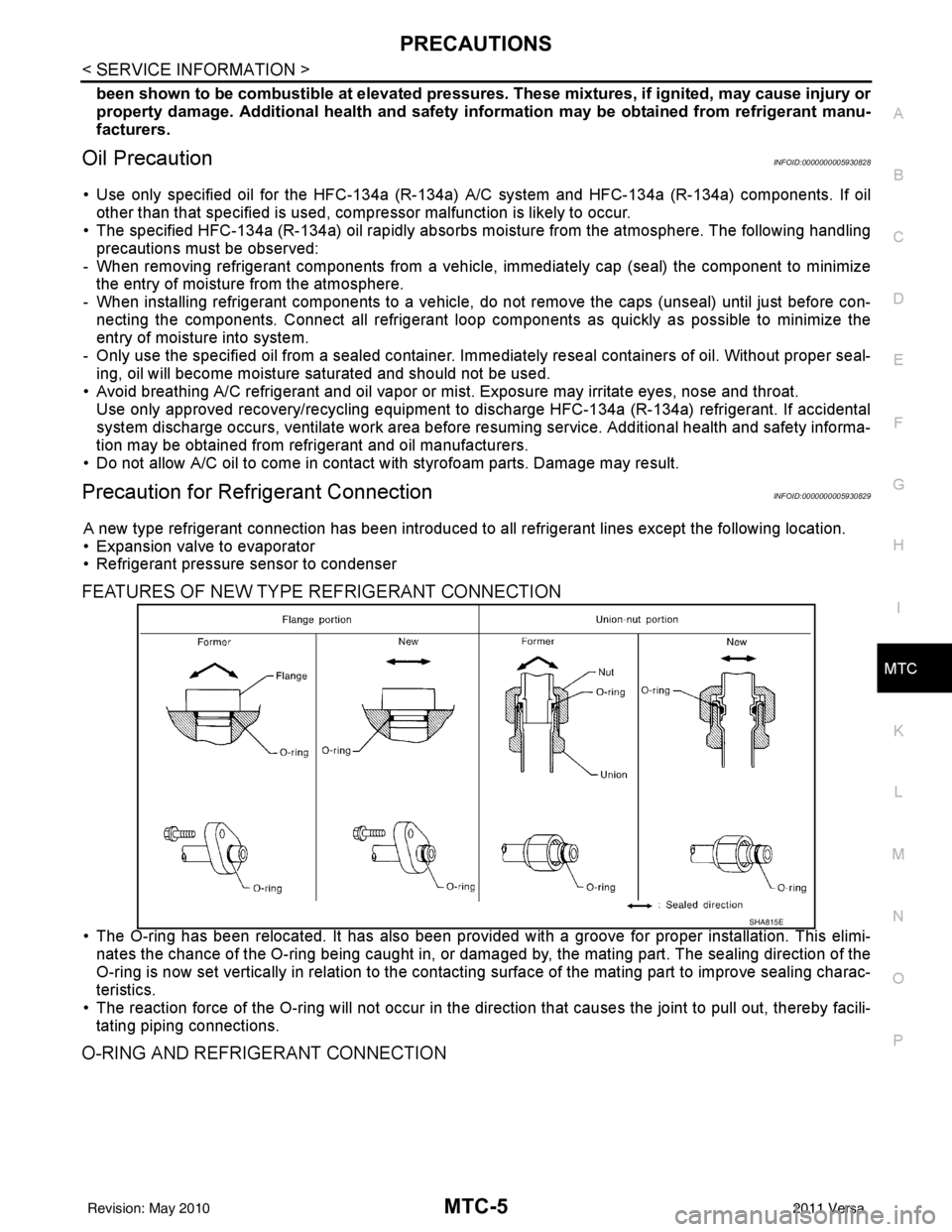
A new type refrigerant connection has been introduced to a ll refrigerant lines except the following location.
• Expansion valve to evaporator
• Refrigerant pressure sensor to condenser
FEATURES OF NEW TYPE REFRIGERANT CONNECTION
• The O-ring has been relocated. It has also been provided with a groove for proper installation. This elimi-
nates the chance of the O-ring being caught in, or damaged by, the mating part. The sealing direction of the
O-ring is now set vertically in relation to the contacti ng surface of the mating part to improve sealing charac-
teristics.
• The reaction force of the O-ring will not occur in the direction that causes the joint to pull out, thereby facili- tating piping connections.
O-RING AND REFRIGERANT CONNECTION
SHA815E
Revision: May 2010 2011 Versa
Page 3323 of 3787
PRECAUTIONSMTC-7
< SERVICE INFORMATION >
C
DE
F
G H
I
K L
M A
B
MTC
N
O P
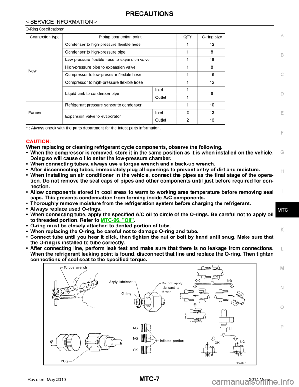
O-Ring Specifications*
* : Always check with the parts department for the latest parts information.
CAUTION:
When replacing or cleaning refrigerant cycle components, observe the following.
• When the compressor is removed, store it in the sam e position as it is when installed on the vehicle.
Doing so will cause oil to en ter the low-pressure chamber.
• When connecting tubes, always use a to rque wrench and a back-up wrench.
• After disconnecting tubes, immediately plug all op enings to prevent entry of dirt and moisture.
• When installing an air conditione r in the vehicle, connect the pipes as the final stage of the opera-
tion. Do not remove the seal caps of pipes and other components until just before required for con-
nection.
• Allow components stored in cool areas to warm to working area temperature before removing seal
caps. This prevents condensation from forming inside A/C components.
• Thoroughly remove moisture from the refrigeration system before charging the refrigerant.
• Always replace used O-rings.
• When connecting tube, apply the speci fied A/C oil to circle of the O-rings. Be careful not to apply oil
to threaded portion. Refer to MTC-96, "
Oil".
• O-ring must be closely attached to dented portion of tube.
• When replacing the O-ring, be careful not to damage O-ring and tube.
• Connect tube until you hear it cl ick, then tighten the nut or bolt by hand until snug. Make sure that
the O-ring is installed to tube correctly.
• After connecting line, perform leak test and make sure that there is no leakage from connections.
When the refrigerant leaking point is found, disconnect that line and replace the O-ring. Then tighten
connections of seal seat to the specified torque.
Connection type Piping connection point QTY O-ring size
New Condenser to high-pressure flexible hose
112
Condenser to high-pressure pipe 18
Low-pressure flexible hose to expansion valve 116
High-pressure pipe to expansion valve 18
Compressor to low-pressure flexible hose 119
Compressor to high-pressure flexible hose 112
Liquid tank to condenser pipe Inlet
1
8
Outlet 1
Former Refrigerant pressure sensor to condenser
110
Expansion valve to evaporator Inlet
212
Outlet 2 16
RHA861F
Revision: May 2010 2011 Versa
Page 3324 of 3787
MTC-8
< SERVICE INFORMATION >
PRECAUTIONS
Precaution for Service of Compressor
INFOID:0000000005930830
• Plug all openings to prevent moisture and foreign matter from entering.
• When the compressor is removed, store it in th e same position as it is when mounted on the car.
• When replacing or repairing compressor, follow “Maintenance of Oil Quantity in Compressor”
exactly. Refer to MTC-17, "
Maintenance of Oil Quantity in Compressor".
• Keep friction surfaces between clut ch and pulley clean. If the surface is contaminated, with oil, wipe
it off by using a clean waste cloth moistened with thinner.
• After compressor service operation, turn the compresso r shaft by hand more than five turns in both
directions. This will equally distribute oil inside the compressor. After the compressor is installed,
let the engine idle and operate the compressor for one hour.
• After replacing the compressor magnet clutch, ap ply voltage to the new one and check for usual
operation.
Precaution for Service EquipmentINFOID:0000000005930831
RECOVERY/RECYCLING EQUIPMENT
Be certain to follow the manufacturer’s instructions for machine operation and machine maintenance. Never
introduce any refrigerant other than that specified into the machine.
ELECTRONIC LEAK DETECTOR
Be certain to follow the manufacturer’s instruct ions for tester operation and tester maintenance.
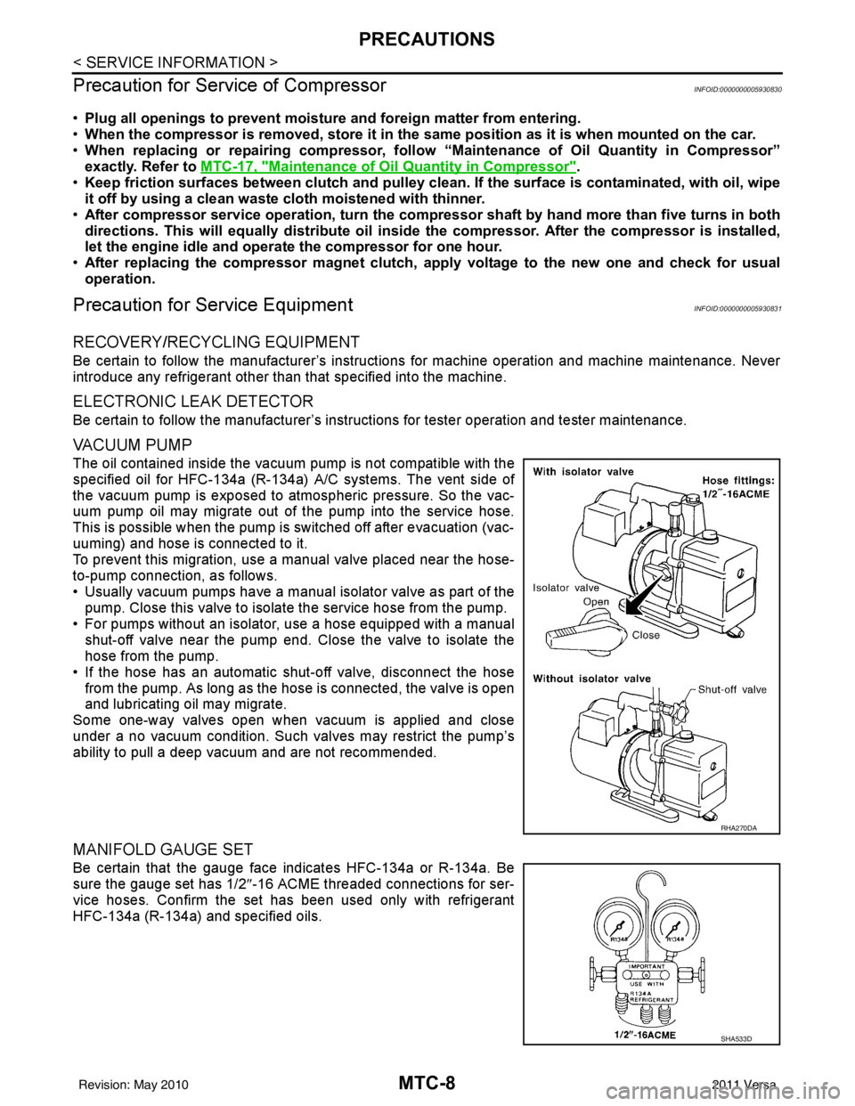
VACUUM PUMP
The oil contained inside the vacuum pump is not compatible with the
specified oil for HFC-134a (R-134a) A/C systems. The vent side of
the vacuum pump is exposed to atmospheric pressure. So the vac-
uum pump oil may migrate out of the pump into the service hose.
This is possible when the pump is switched off after evacuation (vac-
uuming) and hose is connected to it.
To prevent this migration, use a manual valve placed near the hose-
to-pump connection, as follows.
• Usually vacuum pumps have a manual isolator valve as part of the pump. Close this valve to isolat e the service hose from the pump.
• For pumps without an isolator, use a hose equipped with a manual shut-off valve near the pump end. Close the valve to isolate the
hose from the pump.
• If the hose has an automatic shut -off valve, disconnect the hose
from the pump. As long as the hose is connected, the valve is open
and lubricating oil may migrate.
Some one-way valves open when vacuum is applied and close
under a no vacuum condition. Such valves may restrict the pump’s
ability to pull a deep vacuum and are not recommended.
MANIFOLD GAUGE SET
Be certain that the gauge face indicates HFC-134a or R-134a. Be
sure the gauge set has 1/2 ″-16 ACME threaded connections for ser-
vice hoses. Confirm the set has been used only with refrigerant
HFC-134a (R-134a) and specified oils.
RHA270DA
SHA533D
Revision: May 2010 2011 Versa
Page 3339 of 3787
TROUBLE DIAGNOSISMTC-23
< SERVICE INFORMATION >
C
DE
F
G H
I
K L
M A
B
MTC
N
O P
WORK SUPPORT
Display Item List
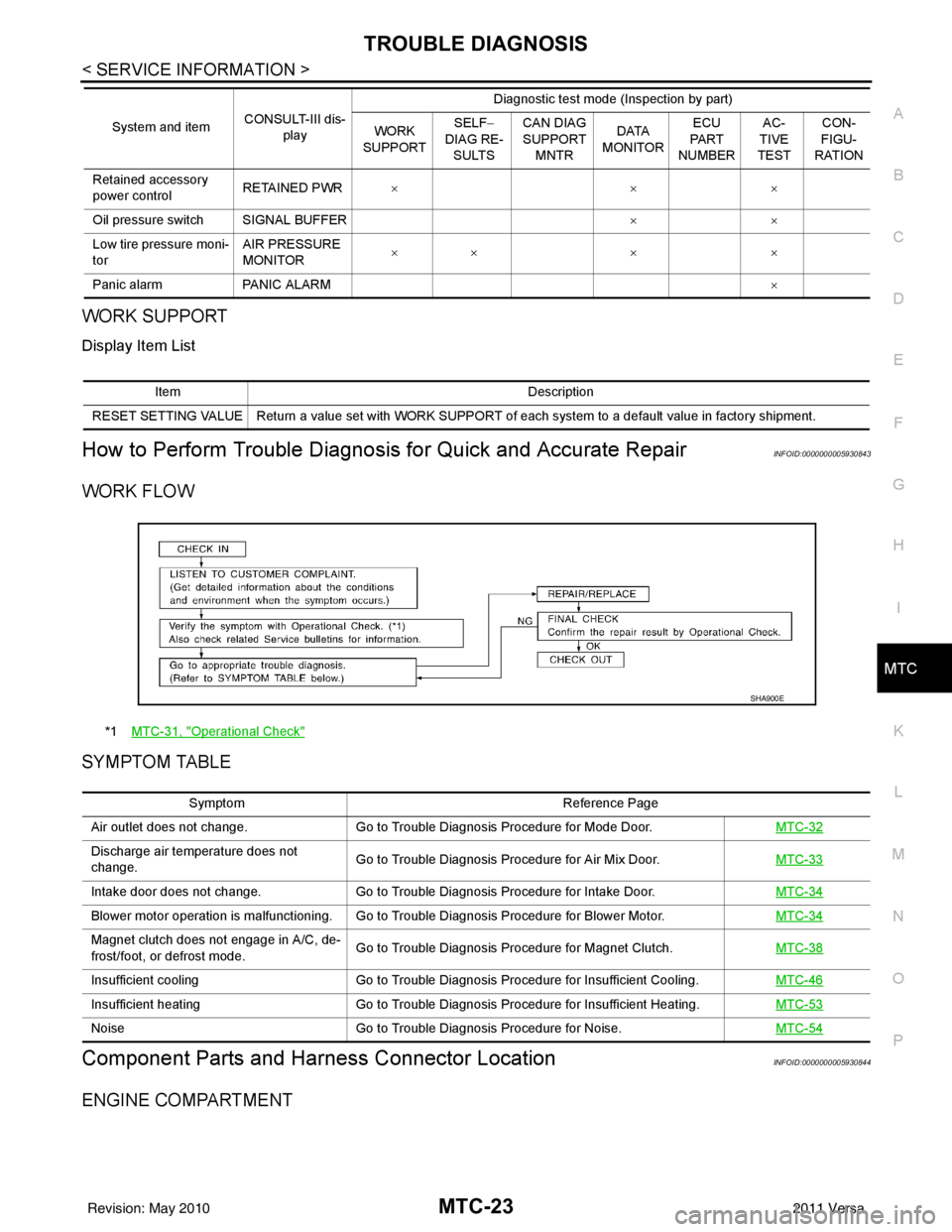
How to Perform Trouble Diagnosis for Quick and Accurate RepairINFOID:0000000005930843
WORK FLOW
SYMPTOM TABLE
Component Parts and Har ness Connector LocationINFOID:0000000005930844
ENGINE COMPARTMENT
Retained accessory
power controlRETAINED PWR
×× ×
Oil pressure switch SIGNAL BUFFER ××
Low tire pressure moni-
tor AIR PRESSURE
MONITOR
××
× ×
Panic alarm PANIC ALARM ×
System and item
CONSULT-III dis-
play Diagnostic test mode (Inspection by part)
WORK
SUPPORT SELF
−
DIAG RE-
SULTS CAN DIAG
SUPPORT
MNTR DATA
MONITOR ECU
PA R T
NUMBER AC-
TIVE
TEST CON-
FIGU-
RATION
Item Description
RESET SETTING VALUE Return a value set with WORK SUPPORT of each system to a default value in factory shipment.
*1 MTC-31, "Operational Check"
SHA900E
Symptom Reference Page
Air outlet does not change. Go to Trouble Diagnosis Procedure for Mode Door. MTC-32
Discharge air temperature does not
change.Go to Trouble Diagnosis Procedure for Air Mix Door.
MTC-33
Intake door does not change.Go to Trouble Diagnosis Procedure for Intake Door. MTC-34
Blower motor operation is malfunctioning. Go to Trouble Diagnosis Procedure for Blower Motor. MTC-34
Magnet clutch does not engage in A/C, de-
frost/foot, or defrost mode.Go to Trouble Diagnosis Procedure for Magnet Clutch.
MTC-38
Insufficient coolingGo to Trouble Diagnosis Procedure for Insufficient Cooling. MTC-46
Insufficient heatingGo to Trouble Diagnosis Procedure for Insufficient Heating. MTC-53
NoiseGo to Trouble Diagnosis Procedure for Noise. MTC-54
Revision: May 2010 2011 Versa
Page 3367 of 3787
TROUBLE DIAGNOSISMTC-51
< SERVICE INFORMATION >
C
DE
F
G H
I
K L
M A
B
MTC
N
O P
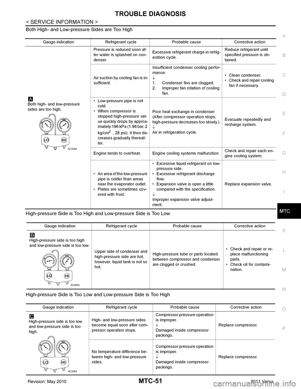
Both High- and Low-pressure Sides are Too High
High-pressure Side is Too High and Low-pressure Side is Too Low
High-pressure Side is Too Low and Low-pressure Side is Too High
Gauge indication
Refrigerant cycle Probable causeCorrective action
Both high- and low-pressure
sides are too high. Pressure is reduced soon af-
ter water is splashed on con-
denser.
Excessive refrigerant charge in refrig-
eration cycle. Reduce refrigerant until
specified pressure is ob-
tained.
Air suction by cooling fan is in-
sufficient. Insufficient condenser cooling perfor-
mance.
↓
1. Condenser fins are clogged.
2. Improper fan rotation of cooling
fan. • Clean condenser.
• Check and repair cooling
fan if necessary.
• Low-pressure pipe is not cold.
• When compressor is
stopped high-pressure val-
ue quickly drops by approx-
imately 196 kPa (1.96 bar, 2
kg/cm
2 , 28 psi). It then de-
creases gradually thereaf-
ter. Poor heat exchange in condenser
(After compressor operation stops,
high-pressure decreases too slowly.).
↓
Air in refrigeration cycle.
Evacuate repeatedly and
recharge system.
Engine tends to overheat. Engine cooling systems malfunction. Check and repair each en-
gine cooling system.
• An area of the low-pressure pipe is colder than areas
near the evaporator outlet.
• Plates are sometimes cov- ered with frost. • Excessive liquid refrigerant on low-
pressure side.
• Excessive refrigerant discharge flow.
• Expansion valve is open a little
compared with the specification.
↓
Improper expansion valve adjust-
ment. Replace expansion valve.
AC359A
Gauge indication
Refrigerant cycle Probable causeCorrective action
High-pressure side is too high
and low-pressure side is too low. Upper side of condenser and
high-pressure side are hot,
however, liquid tank is not so
hot.High-pressure tube or parts located
between compressor and condenser
are clogged or crushed. • Check and repair or re-
place malfunctioning
parts.
• Check oil for contami- nation.
AC360A
Gauge indication Refrigerant cycle Probable causeCorrective action
High-pressure side is too low
and low-pressure side is too
high. High- and low-pressure sides
become equal soon after com-
pressor operation stops. Compressor pressure operation
is improper.
↓
Damaged inside compressor
packings.
Replace compressor.
No temperature difference be-
tween high- and low-pressure
sides. Compressor pressure operation
is improper.
↓
Damaged inside compressor
packings.
Replace compressor.
AC356A
Revision: May 2010
2011 Versa
Page 3368 of 3787
MTC-52
< SERVICE INFORMATION >
TROUBLE DIAGNOSIS
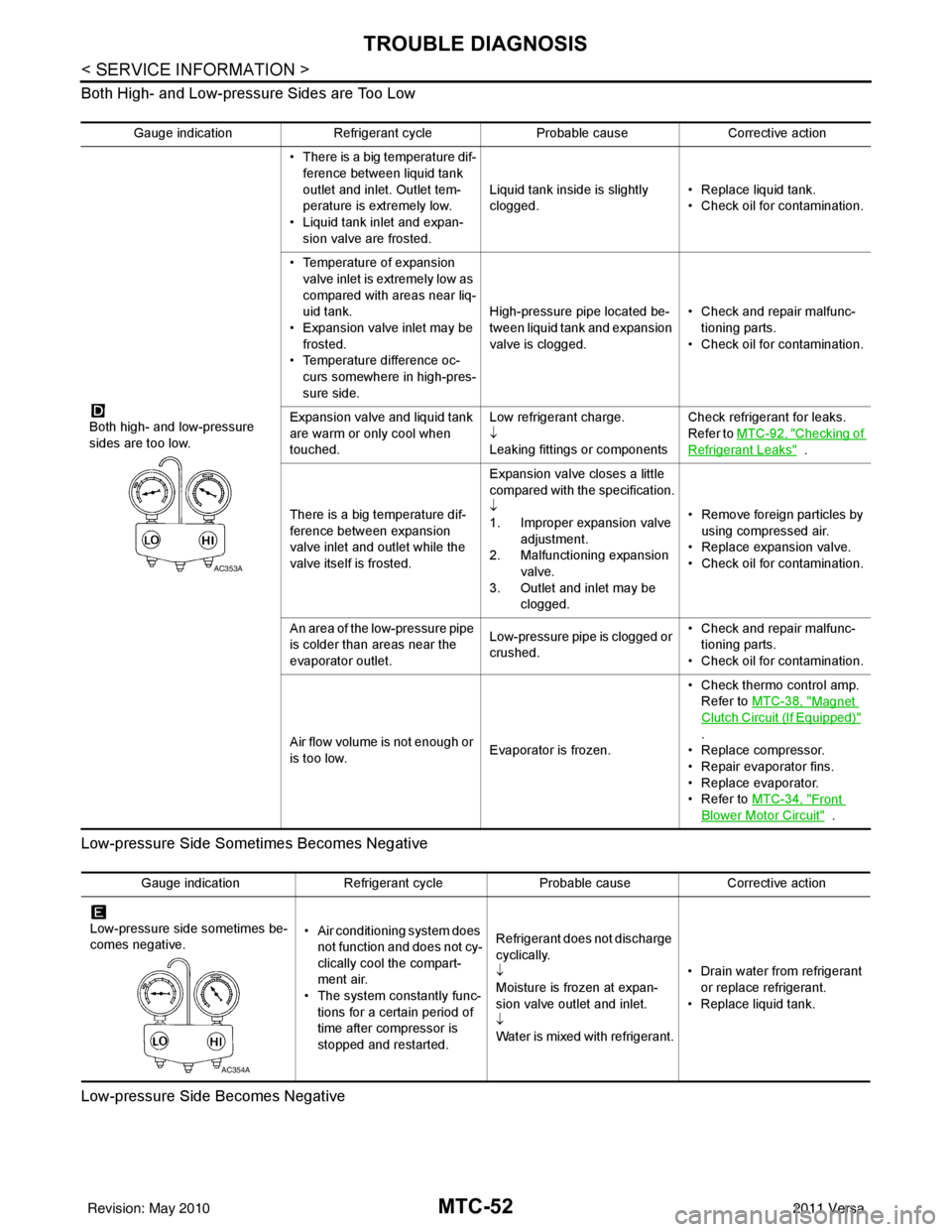
Both High- and Low-pressure Sides are Too Low
Low-pressure Side Sometimes Becomes Negative
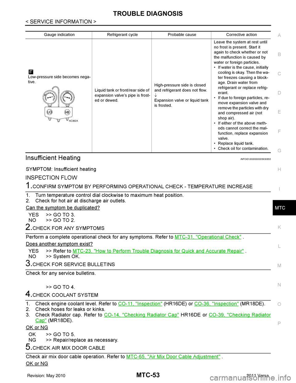
Low-pressure Side Becomes Negative
Gauge indication Refrigerant cycle Probable causeCorrective action
Both high- and low-pressure
sides are too low. • There is a big temperature dif-
ference between liquid tank
outlet and inlet. Outlet tem-
perature is extremely low.
• Liquid tank inlet and expan- sion valve are frosted. Liquid tank inside is slightly
clogged.
• Replace liquid tank.
• Check oil for contamination.
• Temperature of expansion valve inlet is extremely low as
compared with areas near liq-
uid tank.
• Expansion valve inlet may be
frosted.
• Temperature difference oc- curs somewhere in high-pres-
sure side. High-pressure pipe located be-
tween liquid tank and expansion
valve is clogged.
• Check and repair malfunc-
tioning parts.
• Check oil for contamination.
Expansion valve and liquid tank
are warm or only cool when
touched. Low refrigerant charge.
↓
Leaking fittings or componentsCheck refrigerant for leaks.
Refer to
MTC-92, "
Checking of
Refrigerant Leaks" .
There is a big temperature dif-
ference between expansion
valve inlet and outlet while the
valve itself is frosted. Expansion valve closes a little
compared with the specification.
↓
1. Improper expansion valve
adjustment.
2. Malfunctioning expansion valve.
3. Outlet and inlet may be clogged. • Remove foreign particles by
using compressed air.
• Replace expansion valve.
• Check oil for contamination.
An area of the low-pressure pipe
is colder than areas near the
evaporator outlet. Low-pressure pipe is clogged or
crushed.• Check and repair malfunc-
tioning parts.
• Check oil for contamination.
Air flow volume is not enough or
is too low. Evaporator is frozen.• Check thermo control amp.
Refer to MTC-38, "
Magnet
Clutch Circuit (If Equipped)"
.
• Replace compressor.
• Repair evaporator fins.
• Replace evaporator.
•Refer to MTC-34, "
Front
Blower Motor Circuit" .
AC353A
Gauge indication Refrigerant cycleProbable causeCorrective action
Low-pressure side sometimes be-
comes negative. • Air conditioning system does
not function and does not cy-
clically cool the compart-
ment air.
• The system constantly func-
tions for a certain period of
time after compressor is
stopped and restarted. Refrigerant does not discharge
cyclically.
↓
Moisture is frozen at expan-
sion valve outlet and inlet.
↓
Water is mixed with refrigerant.
• Drain water from refrigerant
or replace refrigerant.
• Replace liquid tank.
AC354A
Revision: May 2010 2011 Versa
Page 3369 of 3787
TROUBLE DIAGNOSISMTC-53
< SERVICE INFORMATION >
C
DE
F
G H
I
K L
M A
B
MTC
N
O P
Insufficient HeatingINFOID:0000000005930855
SYMPTOM: Insufficient heating
INSPECTION FLOW
1.CONFIRM SYMPTOM BY PERFORMING OPERAT IONAL CHECK - TEMPERATURE INCREASE
1. Turn temperature control dial clockwise to maximum heat position.
2. Check for hot air at discharge air outlets.
Can the symptom be duplicated?
YES >> GO TO 3.
NO >> GO TO 2.
2.CHECK FOR ANY SYMPTOMS
Perform a complete operational check for any symptoms. Refer to MTC-31, "
Operational Check" .
Does another symptom exist?
YES >> Refer to MTC-23, "How to Perform Trouble Diagnosis for Quick and Accurate Repair" .
NO >> System OK.
3.CHECK FOR SERVICE BULLETINS
Check for any service bulletins.
>> GO TO 4.
4.CHECK COOLANT SYSTEM
1. Check engine coolant level. Refer to CO-11, "
Inspection" (HR16DE) or CO-36, "Inspection" (MR18DE).
2. Check hoses for leaks or kinks.
3. Check Radiator cap. Refer to CO-14, "
Checking Radiator Cap" HR16DE or CO-39, "Checking Radiator
Cap" (MR18DE).
OK or NG
OK >> GO TO 5.
NG >> Repair/replace as necessary.
5.CHECK AIR MIX DOOR CABLE
Check air mix door cable operation. Refer to MTC-65, "
Air Mix Door Cable Adjustment" .
OK or NG
Gauge indication Refrigerant cycleProbable causeCorrective action
Low-pressure side becomes nega-
tive. Liquid tank or front/rear side of
expansion valve’s pipe is frost-
ed or dewed.High-pressure side is closed
and refrigerant does not flow.
↓
Expansion valve or liquid tank
is frosted.Leave the system at rest until
no frost is present. Start it
again to check whether or not
the malfunction is caused by
water or foreign particles.
• If water is the cause, initially
cooling is okay. Then the wa-
ter freezes causing a block-
age. Drain water from
refrigerant or replace refrig-
erant.
• If due to foreign particles, re-
move expansion valve and
remove the particles with dry
and compressed air (not
shop air).
• If either of the above meth- ods cannot correct the mal-
function, replace expansion
valve.
• Replace liquid tank.
• Check oil for contamination.
AC362A
Revision: May 2010 2011 Versa