Page 3340 of 3787
MTC-24
< SERVICE INFORMATION >
TROUBLE DIAGNOSIS
PASSENGER COMPARTMENT
1. Refrigerant pressure sensor E17 (if equipped) 2. A/C compressor F3 (if equipped)
WJIA2235E
Revision: May 2010
2011 Versa
Page 3357 of 3787

TROUBLE DIAGNOSISMTC-41
< SERVICE INFORMATION >
C
DE
F
G H
I
K L
M A
B
MTC
N
O P
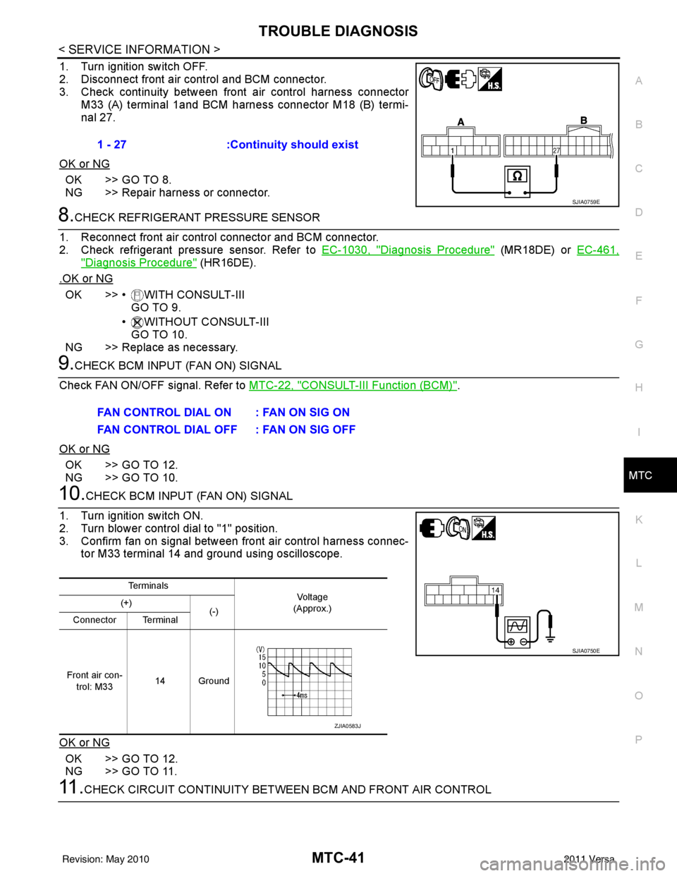
1. Turn ignition switch OFF.
2. Disconnect front air control and BCM connector.
3. Check continuity between front air control harness connector
M33 (A) terminal 1and BCM harness connector M18 (B) termi-
nal 27.
OK or NG
OK >> GO TO 8.
NG >> Repair harness or connector.
8.CHECK REFRIGERANT PRESSURE SENSOR
1. Reconnect front air control connector and BCM connector.
2. Check refrigerant pressure sensor. Refer to EC-1030, "
Diagnosis Procedure" (MR18DE) or EC-461,
"Diagnosis Procedure" (HR16DE).
.OK or NG
OK >> • WITH CONSULT-III GO TO 9.
• WITHOUT CONSULT-III GO TO 10.
NG >> Replace as necessary.
9.CHECK BCM INPUT (FAN ON) SIGNAL
Check FAN ON/OFF signal. Refer to MTC-22, "
CONSULT-III Function (BCM)".
OK or NG
OK >> GO TO 12.
NG >> GO TO 10.
10.CHECK BCM INPUT (FAN ON) SIGNAL
1. Turn ignition switch ON.
2. Turn blower control dial to "1" position.
3. Confirm fan on signal between front air control harness connec- tor M33 terminal 14 and ground using oscilloscope.
OK or NG
OK >> GO TO 12.
NG >> GO TO 11.
11 .CHECK CIRCUIT CONTINUITY BETWEE N BCM AND FRONT AIR CONTROL
1 - 27
:Continuity should exist
SJIA0759E
FAN CONTROL DIAL ON : FAN ON SIG ON
FAN CONTROL DIAL OFF : FAN ON SIG OFF
Te r m i n a l s
Vo l ta g e
(Approx.)
(+)
(-)
Connector Terminal
Front air con- trol: M33 14 Ground
SJIA0750E
ZJIA0583J
Revision: May 2010
2011 Versa
Page 3370 of 3787

MTC-54
< SERVICE INFORMATION >
TROUBLE DIAGNOSIS
YES >> GO TO 6.
NO >> Adjust or replace air mix door cable. Refer to MTC-65, "
Air Mix Door Cable Adjustment" .
6.CHECK AIR DUCTS
Check ducts for air leaks.
OK or NG
OK >> GO TO 7.
NG >> Repair air leaks.
7.CHECK HEATER HOSE TEMPERATURES
1. Start engine and warm it up to normal operating temperature.
2. Touch both the inlet and outlet heater hoses. The inlet hose should be hot and the outlet hose should be
warm.
Is the inlet hose hot and the outlet hose warm?
YES >> GO TO 8.
NO >> Both hoses warm: GO TO 9.
8.CHECK ENGINE COOLANT TEMPERATURE SENSOR
Check engine control temperature sensor. Refer to EC-172, "
Component Inspection" (MR18DE) or EC-690,
"Component Inspection" (HR16DE).
OK or NG
OK >> System OK.
NG >> Repair or replace as necessary. Retest.
9.CHECK HEATER HOSES
Check heater hoses for proper installation.
OK or NG
OK >> GO TO 10.
NG >> Repair /replace as necessary. Retest GO TO 7.
10.BACK FLUSH HEATER CORE
1. Back flush heater core.
2. Drain the water from the system.
3. Refill system with new engine coolant. Refer to CO-11, "
Changing Engine Coolant" (HR16DE) or CO-36,
"Changing Engine Coolant" (MR18DE) .
4. Start engine and warm it up to normal operating temperature.
5. Touch both the inlet and outlet heater hoses. The inlet hose should be hot and the outlet hose should be
warm.
Is the inlet hose hot and the outlet hose warm?
YES >> System OK.
NO >> Replace heater core and refill engine coolant. Refer to MTC-68, "
Removal and Installation" .
NoiseINFOID:0000000005930856
SYMPTOM: Noise
INSPECTION FLOW
Revision: May 2010 2011 Versa
Page 3392 of 3787
MTC-76
< SERVICE INFORMATION >
REFRIGERANT LINES
Component
INFOID:0000000005930871
MR18DE - Type 1 and HR16DE
WJIA2200E
1. Evaporator 2. Expansion valve 3. Low-pressure service valve
4. High-pressure service valve 5. Refrigerant pressure sensor 6. Shaft seal
7. Drain hose
Revision: May 2010 2011 Versa
Page 3393 of 3787
REFRIGERANT LINESMTC-77
< SERVICE INFORMATION >
C
DE
F
G H
I
K L
M A
B
MTC
N
O P
MR18DE - Type 2
WJIA2202E
1. Evaporator 2. Expansion valve3. Low-pressure service valve
4. High-pressure service valve 5. Refrigerant pressure sensor 6. Shaft seal
7. Drain hose
Revision: May 2010 2011 Versa
Page 3405 of 3787

REFRIGERANT LINESMTC-89
< SERVICE INFORMATION >
C
DE
F
G H
I
K L
M A
B
MTC
N
O P
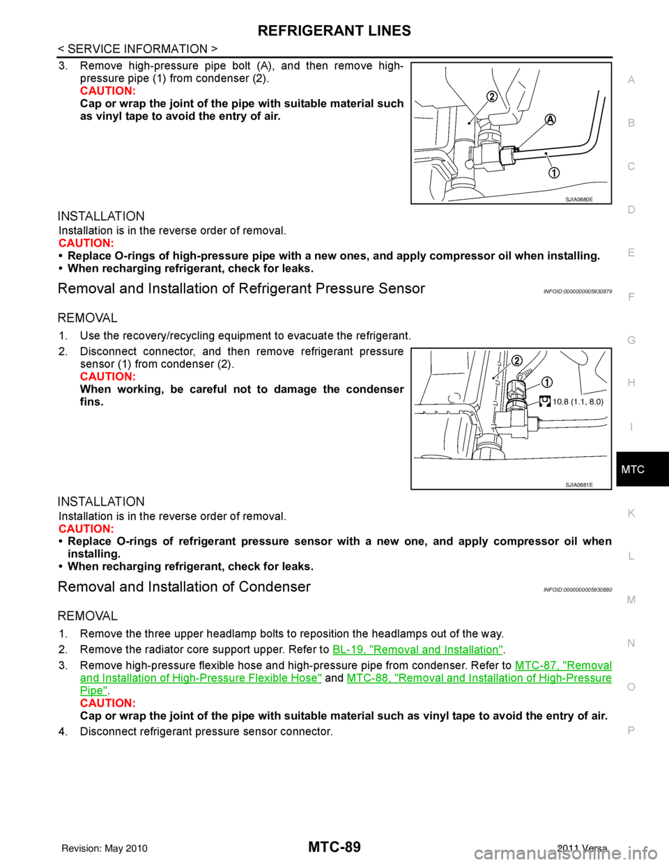
3. Remove high-pressure pipe bolt (A), and then remove high- pressure pipe (1) from condenser (2).
CAUTION:
Cap or wrap the joint of the pi pe with suitable material such
as vinyl tape to avoid the entry of air.
INSTALLATION
Installation is in the reverse order of removal.
CAUTION:
• Replace O-rings of high-pressure pipe with a new ones, and apply compr essor oil when installing.
• When recharging refrigerant, check for leaks.
Removal and Installation of Refrigerant Pressure SensorINFOID:0000000005930879
REMOVAL
1. Use the recovery/recycling equipment to evacuate the refrigerant.
2. Disconnect connector, and then remove refrigerant pressure
sensor (1) from condenser (2).
CAUTION:
When working, be careful not to damage the condenser
fins.
INSTALLATION
Installation is in the reverse order of removal.
CAUTION:
• Replace O-rings of refrigerant pressure senso r with a new one, and apply compressor oil when
installing.
• When recharging refrigerant, check for leaks.
Removal and Installation of CondenserINFOID:0000000005930880
REMOVAL
1. Remove the three upper headlamp bolts to reposition the headlamps out of the way.
2. Remove the radiator core support upper. Refer to BL-19, "
Removal and Installation".
3. Remove high-pressure flexible hose and high-pressure pipe from condenser. Refer to MTC-87, "
Removal
and Installation of High-Pressure Flexible Hose" and MTC-88, "Removal and Installation of High-Pressure
Pipe".
CAUTION:
Cap or wrap the joint of the pipe with suitable ma terial such as vinyl tape to avoid the entry of air.
4. Disconnect refrigerant pr essure sensor connector.
SJIA0680E
SJIA0681E
Revision: May 2010 2011 Versa
Page 3409 of 3787

REFRIGERANT LINESMTC-93
< SERVICE INFORMATION >
C
DE
F
G H
I
K L
M A
B
MTC
N
O P
Other gases in the work area or substances on the A/C components, for example, anti-freeze, windshield
washer fluid, solvents and oils, may falsely trigger the leak detector. Make sure the surfaces to be checked are
clean.
Clean with a dry cloth or blow off with shop air.
Do not allow the sensor tip of the detector to contact with any substance. This can also cause false readings
and may damage the detector.
Dye InjectionINFOID:0000000005930886
(This procedure is only necessary when recharging t he system or when the compressor has seized and was
replaced.)
1. Check A/C system static (at rest) pressure. Pres sure must be at least 345 kPa (3.45 bar, 3.52 kg/cm
2, 50
psi).
2. Pour one bottle (1/4 ounce / 7.4 cc) of the A/C refrigerant dye into the injector tool J-41459.
3. Connect the injector tool to the A/C low-pressure side service fitting.
4. Start engine and switch A/C ON.
5. When the A/C operating (compressor running), inject one bottle (1/4 ounce / 7.4 cc) of fluorescent dye
through the low-pressure service valve using dye injector tool J-41459 (refer to the manufacture’s operat-
ing instructions).
6. With the engine still running, disconnect the injector tool from the service fitting.
CAUTION:
Be careful the A/C system or replacing a componen t, pour the dye directly into the open system
connection and proceed wi th the service procedures.
7. Operate the A/C system for a minimum of 20 minutes to mix the dye with the system oil. Depending on the
leak size, operating conditions and location of the leak , it may take from minutes to days for the dye to
penetrate a leak and become visible.
Electronic Refrigerant Leak DetectorINFOID:0000000005930887
PRECAUTIONS FOR HANDLING LEAK DETECTOR
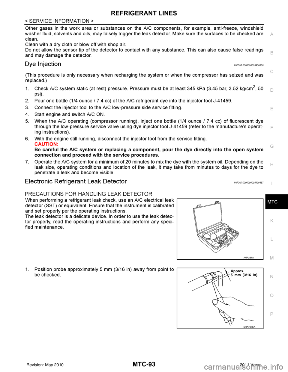
When performing a refrigerant leak check, use an A/C electrical leak
detector (SST) or equivalent. Ensure that the instrument is calibrated
and set properly per the operating instructions.
The leak detector is a delicate device. In order to use the leak detec-
tor properly, read the operating instructions and perform any speci-
fied maintenance.
1. Position probe approximately 5 mm (3/16 in) away from point to
be checked.
AHA281A
SHA707EA
Revision: May 2010 2011 Versa
Page 3410 of 3787

MTC-94
< SERVICE INFORMATION >
REFRIGERANT LINES
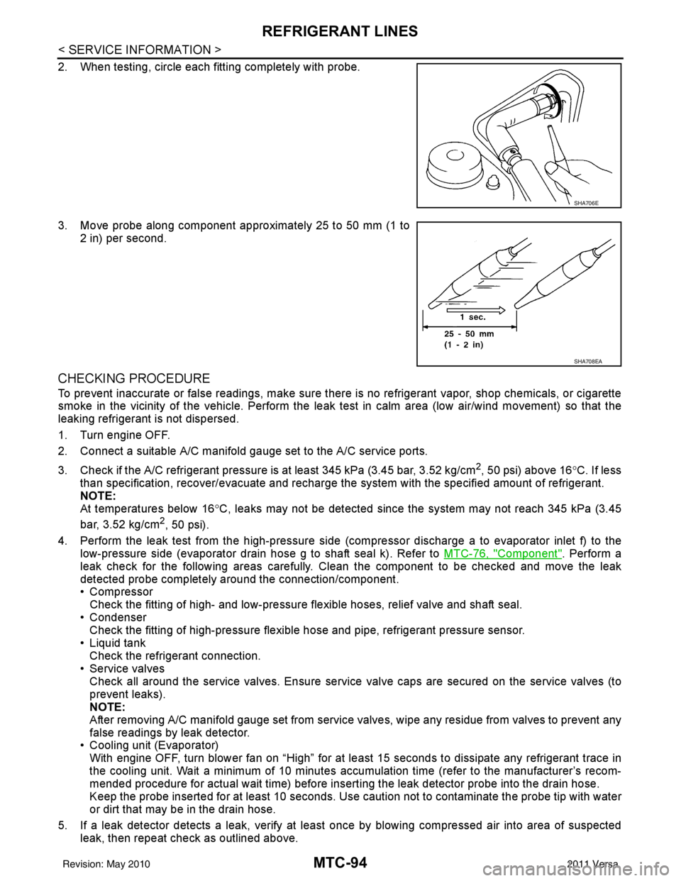
2. When testing, circle each fitting completely with probe.
3. Move probe along component approximately 25 to 50 mm (1 to2 in) per second.
CHECKING PROCEDURE
To prevent inaccurate or false readings, make sure there is no refrigerant vapor, shop chemicals, or cigarette
smoke in the vicinity of the vehicle. Perform the leak test in calm area (low air/wind movement) so that the
leaking refrigerant is not dispersed.
1. Turn engine OFF.
2. Connect a suitable A/C manifold gauge set to the A/C service ports.
3. Check if the A/C refrigerant pressure is at least 345 kPa (3.45 bar, 3.52 kg/cm
2, 50 psi) above 16°C. If less
than specification, recover/evacuate and recharge the system with the specified amount of refrigerant.
NOTE:
At temperatures below 16 °C, leaks may not be detected since t he system may not reach 345 kPa (3.45
bar, 3.52 kg/cm
2, 50 psi).
4. Perform the leak test from the high-pressure side (compressor dischar ge a to evaporator inlet f) to the
low-pressure side (evaporator drain hose g to shaft seal k). Refer to MTC-76, "
Component". Perform a
leak check for the following areas carefully. Clean the component to be checked and move the leak
detected probe completely around the connection/component.
• Compressor Check the fitting of high- and low-pressure flexible hoses, relief valve and shaft seal.
• Condenser Check the fitting of high-pressure flexible hose and pipe, refrigerant pressure sensor.
• Liquid tank Check the refrigerant connection.
• Service valves
Check all around the service valves. Ensure service valve caps are secured on the service valves (to
prevent leaks).
NOTE:
After removing A/C manifold gauge set from service valves, wipe any residue from valves to prevent any
false readings by leak detector.
• Cooling unit (Evaporator)
With engine OFF, turn blower fan on “High” for at l east 15 seconds to dissipate any refrigerant trace in
the cooling unit. Wait a minimum of 10 minutes accumulation time (refer to the manufacturer’s recom-
mended procedure for actual wait time) before insert ing the leak detector probe into the drain hose.
Keep the probe inserted for at least 10 seconds. Use c aution not to contaminate the probe tip with water
or dirt that may be in the drain hose.
5. If a leak detector detects a leak, verify at least once by blowing compressed air into area of suspected
leak, then repeat check as outlined above.
SHA706E
SHA708EA
Revision: May 2010 2011 Versa