2011 NISSAN LATIO sensor
[x] Cancel search: sensorPage 3276 of 3787
![NISSAN LATIO 2011 Service Repair Manual VEHICLE SPEED SENSORMT-55
< SERVICE INFORMATION > [RS6F94R]
D
E
F
G H
I
J
K L
M A
B
MT
N
O P
VEHICLE SPEED SENSOR
Removal and InstallationINFOID:0000000005929690
REMOVAL
1. Disconnect vehicle speed se NISSAN LATIO 2011 Service Repair Manual VEHICLE SPEED SENSORMT-55
< SERVICE INFORMATION > [RS6F94R]
D
E
F
G H
I
J
K L
M A
B
MT
N
O P
VEHICLE SPEED SENSOR
Removal and InstallationINFOID:0000000005929690
REMOVAL
1. Disconnect vehicle speed se](/manual-img/5/57357/w960_57357-3275.png)
VEHICLE SPEED SENSORMT-55
< SERVICE INFORMATION > [RS6F94R]
D
E
F
G H
I
J
K L
M A
B
MT
N
O P
VEHICLE SPEED SENSOR
Removal and InstallationINFOID:0000000005929690
REMOVAL
1. Disconnect vehicle speed sensor.
2. Remove vehicle speed sensor.
INSTALLATION
Installation is in the reverse order of removal.
Revision: May 2010 2011 Versa
Page 3284 of 3787
![NISSAN LATIO 2011 Service Repair Manual TRANSAXLE ASSEMBLYMT-63
< SERVICE INFORMATION > [RS6F94R]
D
E
F
G H
I
J
K L
M A
B
MT
N
O P
Gear Components
1. Filler plug 2. Gasket 3. Transaxle case
4. Bushing 5. Snap ring 6. Oil channel
7. Oil gutt NISSAN LATIO 2011 Service Repair Manual TRANSAXLE ASSEMBLYMT-63
< SERVICE INFORMATION > [RS6F94R]
D
E
F
G H
I
J
K L
M A
B
MT
N
O P
Gear Components
1. Filler plug 2. Gasket 3. Transaxle case
4. Bushing 5. Snap ring 6. Oil channel
7. Oil gutt](/manual-img/5/57357/w960_57357-3283.png)
TRANSAXLE ASSEMBLYMT-63
< SERVICE INFORMATION > [RS6F94R]
D
E
F
G H
I
J
K L
M A
B
MT
N
O P
Gear Components
1. Filler plug 2. Gasket 3. Transaxle case
4. Bushing 5. Snap ring 6. Oil channel
7. Oil gutter 8. Position switch 9. Bracket
10. Differential side oil seal 11. Magnet 12. Drain plug
13. Input shaft oil seal 14. Clutch housing 15. Two way connector
16. Plug (With ABS models) 17. Vehi cle speed sensor (Without
ABS models) 18. Pinion shaft
19. Pinion gear Use specified transaxle fluid. Refer to MA-14, "
Fluids and Lubricants"
: Apply Genuine Liquid Gasket, Three Bond 1215 or an equivalent.
AWDIA0715ZZ
Revision: May 2010 2011 Versa
Page 3294 of 3787
![NISSAN LATIO 2011 Service Repair Manual TRANSAXLE ASSEMBLYMT-73
< SERVICE INFORMATION > [RS6F94R]
D
E
F
G H
I
J
K L
M A
B
MT
N
O P
31. Remove bushing (1) from clutch housing, using suitable tool.
32. Remove two way connector (1) from clutch NISSAN LATIO 2011 Service Repair Manual TRANSAXLE ASSEMBLYMT-73
< SERVICE INFORMATION > [RS6F94R]
D
E
F
G H
I
J
K L
M A
B
MT
N
O P
31. Remove bushing (1) from clutch housing, using suitable tool.
32. Remove two way connector (1) from clutch](/manual-img/5/57357/w960_57357-3293.png)
TRANSAXLE ASSEMBLYMT-73
< SERVICE INFORMATION > [RS6F94R]
D
E
F
G H
I
J
K L
M A
B
MT
N
O P
31. Remove bushing (1) from clutch housing, using suitable tool.
32. Remove two way connector (1) from clutch housing.
33. Remove plug from clutch housing. (With ABS models)
34. Remove vehicle speed sensor from clutch housing. (Without ABS models)
35. Remove pinion gear (1) and pinion shaft (2) from clutch housing.
ASSEMBLY
1. Install pinion gear (1) and pinion shaft (2) to clutch housing. CAUTION:
Replace transaxle assembly when replacing clutch hous-
ing.
2. Install plug to clutch housing. (With ABS models)
3. Install vehicle speed sensor to clutch housing. (Without ABS models)
NOTE:
Apply specified transaxle fluid to O-rings prior to installation.
Refer to MA-14, "
Fluids and Lubricants".
PCIB1717E
PCIB1720E
PCIB1719E
PCIB1719E
Revision: May 2010 2011 Versa
Page 3318 of 3787

MTC-2
REFRIGERANT LINES ......................................74
HFC-134a (R-134a) Service Procedure .............. ...74
Component .............................................................76
Removal and Installation of Compressor -
HR16DE .................................................................
78
Removal and Installation of Compressor -
MR18DE .................................................................
80
Removal and Installation for Compressor Clutch -
Type 1 .................................................................. ...
81
Removal and Installation for Compressor Clutch -
Type 2 .................................................................. ...
83
Removal and Installation of Low-Pressure Flexi-
ble Hose .................................................................
86
Removal and Installation of High-Pressure Flexi-
ble Hose .................................................................
87
Removal and Installation of High-Pressure Pipe ....88
Removal and Installation of Refrigerant Pressure
Sensor .................................................................. ...
89
Removal and Installation of Condenser ..................89
Removal and Installation of Liquid Tank .................90
Removal and Installation of Evaporator ............... ...91
Removal and Installation of Expansion Valve .........92
Checking of Refrigerant Leaks ................................92
Checking System for Leaks Using the Fluorescent
Leak Detector ..........................................................
92
Dye Injection ...........................................................93
Electronic Refrigerant Leak Detector ......................93
SERVICE DATA AND SPECIFICATIONS
(SDS) .................................................................
96
Compressor ......................................................... ...96
Oil ............................................................................96
Refrigerant ..............................................................96
Revision: May 2010 2011 Versa
Page 3319 of 3787

PRECAUTIONSMTC-3
< SERVICE INFORMATION >
C
DE
F
G H
I
K L
M A
B
MTC
N
O P
SERVICE INFORMATION
PRECAUTIONS
Precaution for Supplemental Restraint System (SRS) "AIR BAG" and "SEAT BELT
PRE-TENSIONER"
INFOID:0000000006412028
The Supplemental Restraint System such as “AIR BAG” and “SEAT BELT PRE-TENSIONER”, used along
with a front seat belt, helps to reduce the risk or severi ty of injury to the driver and front passenger for certain
types of collision. This system includes seat belt switch inputs and dual stage front air bag modules. The SRS
system uses the seat belt switches to determine the front air bag deployment, and may only deploy one front
air bag, depending on the severity of a collision and w hether the front occupants are belted or unbelted.
Information necessary to service the system safely is included in the SRS and SB section of this Service Man-
ual.
WARNING:
• To avoid rendering the SRS inoper ative, which could increase the risk of personal injury or death in
the event of a collision which would result in air bag inflation, all maintenance must be performed by
an authorized NISSAN/INFINITI dealer.
• Improper maintenance, including in correct removal and installation of the SRS can lead to personal
injury caused by unintentional act ivation of the system. For removal of Spiral Cable and Air Bag
Module, see the SRS section.
• Do not use electrical test equipm ent on any circuit related to the SRS unless instructed to in this
Service Manual. SRS wiring harnesses can be identi fied by yellow and/or orange harnesses or har-
ness connectors.
PRECAUTIONS WHEN USING POWER TOOLS (AIR OR ELECTRIC) AND HAMMERS
WARNING:
• When working near the Airbag Diagnosis Sensor Un it or other Airbag System sensors with the Igni-
tion ON or engine running, DO NOT use air or el ectric power tools or strike near the sensor(s) with a
hammer. Heavy vibration could activate the sensor( s) and deploy the air bag(s), possibly causing
serious injury.
• When using air or electric power tools or hammers, always switch the Ignition OFF, disconnect the battery, and wait at least 3 minutes before performing any service.
Precaution Necessary for Steering Wheel Rotation After Battery Disconnect
INFOID:0000000005930824
NOTE:
• This Procedure is applied only to models with Intelligent Key system and NATS (NISSAN ANTI-THEFT SYS-
TEM).
• Remove and install all control units after disconnecti ng both battery cables with the ignition knob in the
″ LOCK ″ position.
• Always use CONSULT-III to perform self-diagnosis as a part of each function inspection after finishing work.
If DTC is detected, perform trouble diagnosis according to self-diagnostic results.
For models equipped with the Intelligent Key system and NATS , an electrically controlled steering lock mech-
anism is adopted on the key cylinder.
For this reason, if the battery is disconnected or if the battery is discharged, the steering wheel will lock and
steering wheel rotation will become impossible.
If steering wheel rotation is required when battery power is interrupted, follow the procedure below before
starting the repair operation.
OPERATION PROCEDURE
1. Connect both battery cables. NOTE:
Supply power using jumper cables if battery is discharged.
2. Use the Intelligent Key or mechanical key to turn the ignition switch to the ″ACC ″ position. At this time, the
steering lock will be released.
3. Disconnect both battery cables. The steering lock will remain released and the steering wheel can be
rotated.
4. Perform the necessary repair operation.
Revision: May 2010 2011 Versa
Page 3321 of 3787

PRECAUTIONSMTC-5
< SERVICE INFORMATION >
C
DE
F
G H
I
K L
M A
B
MTC
N
O P
been shown to be combustible at elevated pressures. These mixtures, if ignited, may cause injury or
property damage. Additional health and safety info rmation may be obtained from refrigerant manu-
facturers.
Oil PrecautionINFOID:0000000005930828
• Use only specified oil for the HFC-134a (R-134a) A/C system and HFC-134a (R-134a) components. If oil
other than that specified is used, comp ressor malfunction is likely to occur.
• The specified HFC-134a (R-134a) oil rapidly absorbs moisture from the atmosphere. The following handling
precautions must be observed:
- When removing refrigerant components from a vehicle, immediately cap (seal) the component to minimize the entry of moisture from the atmosphere.
- When installing refrigerant components to a vehicle, do not remove the caps (unseal) until just before con- necting the components. Connect all refrigerant loop components as quickly as possible to minimize the
entry of moisture into system.
- Only use the specified oil from a sealed container. Imm ediately reseal containers of oil. Without proper seal-
ing, oil will become moisture saturated and should not be used.
• Avoid breathing A/C refrigerant and oil vapor or mist. Exposure may irritate eyes, nose and throat.
Use only approved recovery/recycling equipment to discharge HFC-134a (R-134a) refrigerant. If accidental
system discharge occurs, ventilate work area before resuming service. Additional health and safety informa-
tion may be obtained from refrigerant and oil manufacturers.
• Do not allow A/C oil to come in contact with styrofoam parts. Damage may result.
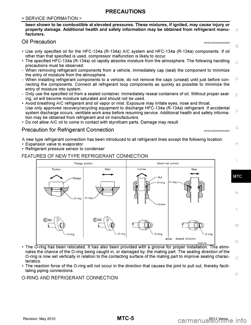
Precaution for Refrigerant ConnectionINFOID:0000000005930829
A new type refrigerant connection has been introduced to a ll refrigerant lines except the following location.
• Expansion valve to evaporator
• Refrigerant pressure sensor to condenser
FEATURES OF NEW TYPE REFRIGERANT CONNECTION
• The O-ring has been relocated. It has also been provided with a groove for proper installation. This elimi-
nates the chance of the O-ring being caught in, or damaged by, the mating part. The sealing direction of the
O-ring is now set vertically in relation to the contacti ng surface of the mating part to improve sealing charac-
teristics.
• The reaction force of the O-ring will not occur in the direction that causes the joint to pull out, thereby facili- tating piping connections.
O-RING AND REFRIGERANT CONNECTION
SHA815E
Revision: May 2010 2011 Versa
Page 3323 of 3787

PRECAUTIONSMTC-7
< SERVICE INFORMATION >
C
DE
F
G H
I
K L
M A
B
MTC
N
O P
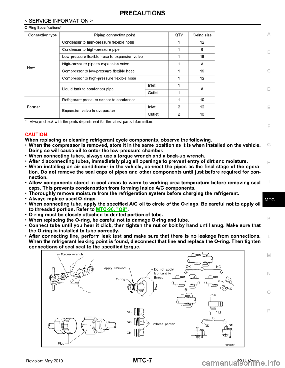
O-Ring Specifications*
* : Always check with the parts department for the latest parts information.
CAUTION:
When replacing or cleaning refrigerant cycle components, observe the following.
• When the compressor is removed, store it in the sam e position as it is when installed on the vehicle.
Doing so will cause oil to en ter the low-pressure chamber.
• When connecting tubes, always use a to rque wrench and a back-up wrench.
• After disconnecting tubes, immediately plug all op enings to prevent entry of dirt and moisture.
• When installing an air conditione r in the vehicle, connect the pipes as the final stage of the opera-
tion. Do not remove the seal caps of pipes and other components until just before required for con-
nection.
• Allow components stored in cool areas to warm to working area temperature before removing seal
caps. This prevents condensation from forming inside A/C components.
• Thoroughly remove moisture from the refrigeration system before charging the refrigerant.
• Always replace used O-rings.
• When connecting tube, apply the speci fied A/C oil to circle of the O-rings. Be careful not to apply oil
to threaded portion. Refer to MTC-96, "
Oil".
• O-ring must be closely attached to dented portion of tube.
• When replacing the O-ring, be careful not to damage O-ring and tube.
• Connect tube until you hear it cl ick, then tighten the nut or bolt by hand until snug. Make sure that
the O-ring is installed to tube correctly.
• After connecting line, perform leak test and make sure that there is no leakage from connections.
When the refrigerant leaking point is found, disconnect that line and replace the O-ring. Then tighten
connections of seal seat to the specified torque.
Connection type Piping connection point QTY O-ring size
New Condenser to high-pressure flexible hose
112
Condenser to high-pressure pipe 18
Low-pressure flexible hose to expansion valve 116
High-pressure pipe to expansion valve 18
Compressor to low-pressure flexible hose 119
Compressor to high-pressure flexible hose 112
Liquid tank to condenser pipe Inlet
1
8
Outlet 1
Former Refrigerant pressure sensor to condenser
110
Expansion valve to evaporator Inlet
212
Outlet 2 16
RHA861F
Revision: May 2010 2011 Versa
Page 3331 of 3787

REFRIGERATION SYSTEMMTC-15
< SERVICE INFORMATION >
C
DE
F
G H
I
K L
M A
B
MTC
N
O P
REFRIGERATION SYSTEM
Refrigerant CycleINFOID:0000000005930835
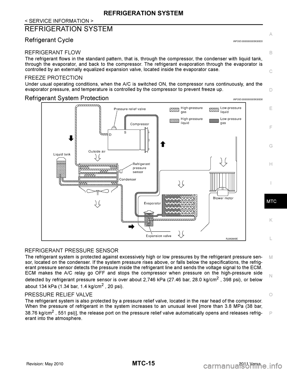
REFRIGERANT FLOW
The refrigerant flows in the standard pattern, that is, through the compressor, the condenser with liquid tank,
through the evaporator, and back to the compressor. T he refrigerant evaporation through the evaporator is
controlled by an externally equalized expansion valve, located inside the evaporator case.
FREEZE PROTECTION
Under usual operating conditions, when the A/C is s witched ON, the compressor runs continuously, and the
evaporator pressure, and temperature is controlled by the compressor to prevent freeze up.
Refrigerant System ProtectionINFOID:0000000005930836
REFRIGERANT PRESSURE SENSOR
The refrigerant system is protected against excessively hi gh or low pressures by the refrigerant pressure sen-
sor, located on the condenser. If the system pressure rises above, or falls below the specifications, the refrig-
erant pressure sensor detects the pressure inside t he refrigerant line and sends the voltage signal to the ECM.
ECM makes the A/C relay go OFF and stops the compressor when pressure on the high-pressure side
detected by refrigerant pressure sensor is over about 2,746 kPa (27.46 bar, 28.0 kg/cm
2 , 398 psi), or below
about 134 kPa (1.34 bar, 1.4 kg/cm
2 , 20 psi).
PRESSURE RELIEF VALVE
The refrigerant system is also protected by a pressure relief valve, located in the rear head of the compressor.
When the pressure of refrigerant in the system in creases to an unusual level [more than 3.8 MPa (38 bar,
38.76 kg/cm
2 , 551 psi)], the release port on the pressure relief valve automatically opens and releases refrig-
erant into the atmosphere.
RJIA0849E
Revision: May 2010 2011 Versa