Page 280 of 330

NOTEl Do not allow the wiper arm to fall onto the
windscreen; it could damage the glass.
3. Attach the retainers (C) to a new wiper blade.
Refer to the illustration to ensure that the re-
tainers are correctly aligned as you attach
them.
4. Insert the wiper blade into the arm, starting
with the opposite end of the blade from the
stopper. Make sure the hook (B) is fitted cor-
rectly in the grooves in the blade.
NOTE l If retainers are not supplied with the new wip-
er blade, use the retainers from the old blade.
5. Push the wiper blade until the hook (B) en-
gages securely with the stopper (A).General maintenance E01002700113
Fuel, engine coolant, oil and exhaust
gas leakage
Look under the body of your vehicle to check for
fuel, engine coolant, oil and exhaust gas leaks.WARNINGl If you see a suspicious fuel leak or if you
smell fuel, do not operate the vehicle; we
recommend you to call for assistance.
Exterior and interior lamp operation
Operate the combination lamp switch to check that
all lamps are functioning properly.
If the lamps do not illuminate, the probable cause
is a blown fuse or defective lamp bulb. Check the
fuses first. If there is no blown fuses, check the
lamp bulbs.
For information regarding the inspection and re-
placement of the fuses and the lamp bulbs, refer to
“ Fuses” on page 8-20 and “Replacement of lamp
bulbs” on page 8-23.
If the fuses and bulbs are all OK, we recommend
you to have your vehicle checked and repaired.
Meter, gauge and indicator/warning
lamps operation
Run the engine to check the operation of all meters,
gauges, and indicator/warning lamps.
If there is anything wrong, we recommend you to
have your vehicle inspected.
Maintenance
8-18
8
Page 283 of 330

Passenger compartment fuse location (RHD)
No.SymbolElectrical systemCa-
pacity1Tail lamp (left)7.5 A2Cigarette lighter15 A3Ignition coil10 A4Starter motor7.5 A5Sunroof20 A6Accessory socket15 ANo.SymbolElectrical systemCa-
pacity7Tail lamp (right)7.5 A8Outside rear-view mirrors7.5 A9Engine control unit7.5 A10Control unit7.5 A11Rear fog lamp10 A12Central door lock15 A13Room lamp10 A14Rear window wiper15 A15Gauge7.5 A16Relay7.5 A17Heated seat20 A18Option10 A19Heated door mirror7.5 A20Windscreen wiper20 A21Reversing lamps7.5 A22Demister30 A23Heater30 A24Power seat40 A25Radio10 ANo.SymbolElectrical systemCa-
pacity26Electronic controlled unit15 A27—Spare fuse7.5 A28—Spare fuse20 A29—Spare fuse30 A
l Some fuses may not be installed on your ve-
hicle, depending on the vehicle model or spec-
ifications.
l The table above shows the main equipment
corresponding to each fuse.
The fuse block does not contain spare 10 A
and 15 A fuses. If a fuse of one of these ca-
pacities blows, replace it temporarily by bor-
rowing the one that matches from:
10 A: Radio
15 A: Cigarette lighter
Replace the borrowed fuse as soon as possible.
Maintenance
8-21
8
Page 285 of 330
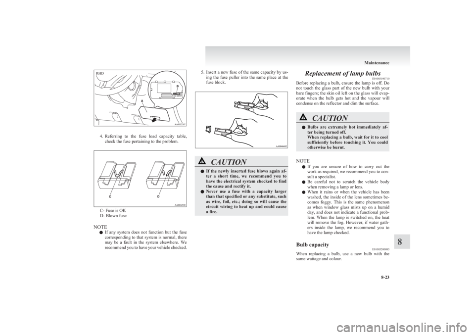
4.Referring to the fuse load capacity table,
check the fuse pertaining to the problem.
C- Fuse is OK
D- Blown fuse
NOTE l If any system does not function but the fuse
corresponding to that system is normal, there
may be a fault in the system elsewhere. We
recommend you to have your vehicle checked.
5. Insert a new fuse of the same capacity by us-
ing the fuse puller into the same place at the
fuse block.CAUTIONl If the newly inserted fuse blows again af-
ter a short time, we recommend you to
have the electrical system checked to find
the cause and rectify it.
l Never use a fuse with a capacity larger
than that specified or any substitute, such
as wire, foil, etc.; doing so will cause the
circuit wiring to heat up and could cause
a fire.Replacement of lamp bulbs E01003100710
Before replacing a bulb, ensure the lamp is off. Do
not touch the glass part of the new bulb with your
bare fingers; the skin oil left on the glass will evap-
orate when the bulb gets hot and the vapour will
condense on the reflector and dim the surface.CAUTIONl Bulbs are extremely hot immediately af-
ter being turned off.
When replacing a bulb, wait for it to cool
sufficiently before touching it. You could
otherwise be burnt.
NOTE
l If you are unsure of how to carry out the
work as required, we recommend you to con-
sult a specialist.
l Be careful not to scratch the vehicle body
when removing a lamp or lens.
l When it rains or when the vehicle has been
washed, the inside of the lens sometimes be-
comes foggy. This is the same phenomenon
as when window glass mists up on a humid
day, and does not indicate a functional prob-
lem. When the lamp is switched on, the heat
will remove the fog. However, if water gath-
ers inside the lamp, we recommend you to
have the lamp checked.
Bulb capacity E01003200085
When replacing a bulb, use a new bulb with the
same wattage and colour.
Maintenance
8-23
8RHD
Page 287 of 330

Club cab
1- Door courtesy lamps*: 3.4 W
2- Front room lamp and personal lamps*:
7.5 W
3- Rear room lamp: 8 W
4- Glove box lamp: 1.4 W
5- Centre console downlight: 1.4 W
Double cab
1- Door courtesy lamps*: 3.4 W
2- Front room lamp and personal lamps: 7.5 W
3- Rear room lamp*: 8 W
4- Glove box lamp: 1.4 W
5- Centre console downlight: 1.4 W
Headlamps E01003501375
Type 1 1.Remove the bulb and connector assembly
(A) by turning it anticlockwise.High beamLow beam2. Depress the tab (B) on the harness connector
and pull the harness connector (C) to remove
it.High beamLow beam
3. To install the bulb, perform the removal
steps in reverse.
CAUTIONl Handle halogen lamp bulbs with care.
The gas inside halogen lamp bulbs is high-
ly pressurized, so dropping, knocking, or
scratching a halogen lamp bulb can cause
it to shatter.
l Never hold the halogen lamp bulb with a
bare hand, dirty glove, etc.
The oil from your hand could cause the
bulb to break the next time the head-
lamps are operated.
If the glass surface is dirty, it must be
cleaned with alcohol, paint thinner, etc.,
and refit it after drying it thoroughly.
Maintenance
8-25
8
Page 288 of 330
Type 21. Disconnect the connector (A).
2. Remove the sealing cover (B).
3.Unhook the spring (C) which secures the
bulb, and then remove the headlamp bulb.
4. To install the bulb, perform the removal
steps in reverse.
CAUTIONl Handle halogen lamp bulbs with care.
The gas inside halogen lamp bulbs is high-
ly pressurized, so dropping, knocking, or
scratching a halogen lamp bulb can cause
it to shatter.
l Never hold the halogen lamp bulb with a
bare hand, dirty glove, etc.
The oil from your hand could cause the
bulb to break the next time the head-
lamps are operated.
If the glass surface is dirty, it must be
cleaned with alcohol, paint thinner, etc.,
and refit it after drying it thoroughly.
Maintenance
8-26
8
Page 291 of 330
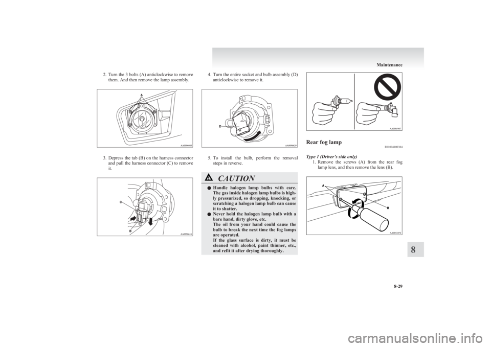
2.Turn the 3 bolts (A) anticlockwise to remove
them. And then remove the lamp assembly.
3. Depress the tab (B) on the harness connector
and pull the harness connector (C) to remove
it.
4. Turn the entire socket and bulb assembly (D)
anticlockwise to remove it.
5. To install the bulb, perform the removal
steps in reverse.
CAUTIONl Handle halogen lamp bulbs with care.
The gas inside halogen lamp bulbs is high-
ly pressurized, so dropping, knocking, or
scratching a halogen lamp bulb can cause
it to shatter.
l Never hold the halogen lamp bulb with a
bare hand, dirty glove, etc.
The oil from your hand could cause the
bulb to break the next time the fog lamps
are operated.
If the glass surface is dirty, it must be
cleaned with alcohol, paint thinner, etc.,
and refit it after drying thoroughly.Rear fog lamp E01004100384
Type 1 (Driver’s side only)
1.Remove the screws (A) from the rear fog
lamp lens, and then remove the lens (B).
Maintenance
8-29
8
Page 314 of 330
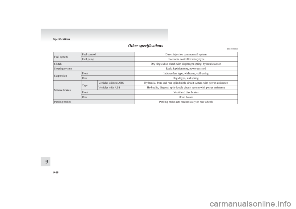
Other specificationsE01101000862Fuel systemFuel controlDirect injection common rail systemFuel pumpElectronic controlled rotary typeClutchDry single disc clutch with diaphragm spring, hydraulic actionSteering systemRack & pinion type, power assistedSuspensionFrontIndependent type, wishbone, coil springRearRigid type, leaf spring
Service brakes
TypeVehicles without ABSHydraulic, front and rear split double circuit system with power assistanceVehicles with ABSHydraulic, diagonal split double circuit system with power assistanceFrontVentilated disc brakesRearDrum brakesParking brakesParking brake acts mechanically on rear wheels
Specifications
9-18
9
Page 318 of 330
![MITSUBISHI L200 2011 Owners Manual (in English) No.ItemQuantityLubricants1Engine coolant8.2 litres
[includes 0.65 litre in the reserve tank]DIA QUEEN SUPER LONG LIFECOOLANT or equivalent2Automatic transmission fluid9.7 litresDIA QUEEN ATF SP III3Br](/manual-img/19/34873/w960_34873-317.png "MITSUBISHI L200 2011 Owners Manual (in English) No.ItemQuantityLubricants1Engine coolant8.2 litres
[includes 0.65 litre in the reserve tank]DIA QUEEN SUPER LONG LIFECOOLANT or equivalent2Automatic transmission fluid9.7 litresDIA QUEEN ATF SP III3Br")
No.ItemQuantityLubricants1Engine coolant8.2 litres
[includes 0.65 litre in the reserve tank]DIA QUEEN SUPER LONG LIFECOOLANT or equivalent2Automatic transmission fluid9.7 litresDIA QUEEN ATF SP III3Brake fluidAs requiredBrake fluid DOT3 or DOT44Clutch fluidAs requiredBrake fluid DOT3 or DOT45Power steering fluidAs requiredATF DEXRON III or DEXRON II
6Engine oil
Oil pan2WD with 15 inch tyres6.5 litres
Refer to page 8-04.
2WD with 16 inch tyres, 4WD5.5 litresOil filter0.8 litreOil cooler0.1 litre7Washer fluid4.8 litres,
4.5 litres* 1—8Manual transmis-
sion oil2WD2.3 litresGear oil API classification GL-3 SAE 75W-854WD3.4 litres9Transfer oil2.5 litresGear oil API classification GL-3 SAE
75W-85 or Gear oil API classification GL-4 SAE 75W-85
10Differential oil
Front*21.2 litres
Gear oil API classification GL-5 or
higher SAE 80WRear
Standard power en-
gine2WD with 15 inch tyres1.5 litres2WD with 16 inch tyres, 4WD2.6 litresHigh power engineA/TM/T3.2 litres11Refrigerant (air conditioning)480-520 g,
535-575 g* 3HFC-134a
*
1
: Vehicles with “front (Type 1)” (Refer to “Outside” on page 8-24)
* 2
: 4WD vehicles only
Specifications
9-22
9