Page 370 of 424
Vehicle care and maintenance
7-35
7 Fuses
N00942800263
Fuse block location
N00901000080
To prevent damage to the electrical system from short-circuit-
ing or overloading, each individual circuit is equipped with a
fuse. The fuse blocks are located in the passenger compartment
and in the engine compartment. Passenger compartmentThe fuse block in the passenger compartment is located in front
of the driver’s seat at the position shown in the illustration.
Engine compartmentIn the engine compartment, the fuse blocks are located as
shown in the illustration.
BK0121200US.book 35 ページ 2010年4月14日 水曜日 午前11時24分
Page 371 of 424
7-36 Vehicle care and maintenance
7
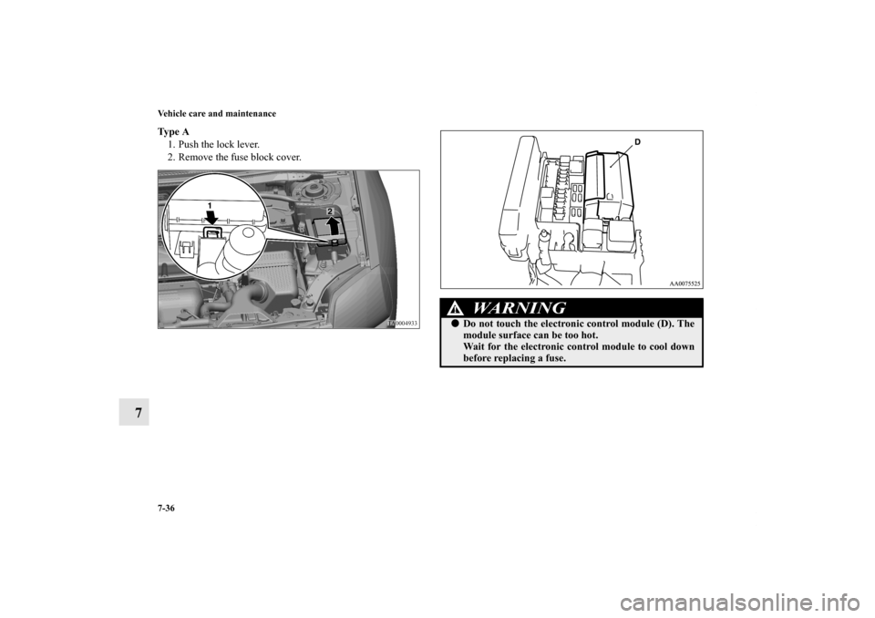
Ty p e A
1. Push the lock lever.
2. Remove the fuse block cover.
WA R N I N G
!�Do not touch the electronic control module (D). The
module surface can be too hot.
Wait for the electronic control module to cool down
before replacing a fuse.
BK0121200US.book 36 ページ 2010年4月14日 水曜日 午前11時24分
Page 372 of 424
Vehicle care and maintenance
7-37
7
Ty p e B
1. Push the lock lever.
2. Remove the relay box cover.Ty p e C
1. Pull the lock lever.
2. Open the cover.
Fuse load capacities
N00954800101
This fuse list shows the names of the electrical systems and
their fuse capacities.
There are spare fuses in the cover of the instrument panel
(driver’s side). Always replace a blown fuse with one of the
same capacity as the original.
BK0121200US.book 37 ページ 2010年4月14日 水曜日 午前11時24分
Page 373 of 424
7-38 Vehicle care and maintenance
7
Passenger compartment fuse location tablePassenger compartment fuse location
No.
Symbol
Electrical system
Capacity
1— — —
2— — —
3Radio 30 A
4 Sunroof 20 A
5 Rear window defogger 30 A
6 Heater 30 A
7— — —
8 — — —
9 Power outlet 15 A
10 Power door locks 15 A
11 — — —
12 — — —
13 Engine control 7.5 A
14 Outside rearview mirrors 7.5 A
15 — — —
16 Cigarette lighter 15 A
17 Engine control 7.5 A
18 — — —
19 Door mirror heater 7.5 A
20 Relay 7.5 A
21 — — —
BK0121200US.book 38 ページ 2010年4月14日 水曜日 午前11時24分
Page 374 of 424
Vehicle care and maintenance
7-39
7
�Some fuses may not be installed on your vehicle, depend-
ing on the vehicle model or specifications.
�The table above shows the main equipment corresponding
to each fuse.
The fuse block does not contain spare 7.5 A, 10 A and 15
A fuses. If a fuse of one of these capacities blows, replace
it temporarily by borrowing the one that matches from:
7.5 A: Door mirror heater
10 A: Radio
15 A: Cigarette lighter
Replace the borrowed fuse as soon as possible.
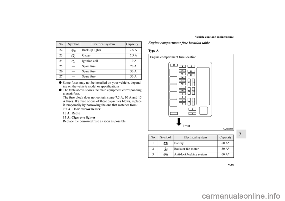
Engine compartment fuse location tableTy p e A
22 Back-up lights 7.5 A
23 Gauge 7.5 A
24 Ignition coil 10 A
25 — Spare fuse 20 A
26 — Spare fuse 30 A
27 — Spare fuse 30 A No.
Symbol
Electrical system
Capacity
No.
Symbol
Electrical system
Capacity
1 Battery 80 A*
2 Radiator fan motor 30 A*
3 Anti-lock braking system 60 A*Engine compartment fuse location
Front
BK0121200US.book 39 ページ 2010年4月14日 水曜日 午前11時24分
Page 377 of 424
7-42 Vehicle care and maintenance
7
Identification of fuse
N00901100065
Fuse replacement
N00954900043
1. Before replacing a fuse, always turn off the electrical item
connected to the fuse and turn the ignition key to the
“LOCK” position.
2. There is a fuse puller in the cover of the instrument panel
(driver’s side).
3. Remove the fuse puller from the cover.
Capacity
Color
7.5 A Brown
10 A Red
15 A Blue
20 A Yellow (fuse type) / Light blue (fusible link type)
30 A Green (fuse type) / Pink (fusible link type)
40 A Green
60 A Yellow
80 A White
BK0121200US.book 42 ページ 2010年4月14日 水曜日 午前11時24分
Page 378 of 424
Vehicle care and maintenance
7-43
7
4. Clamp it on the fuse you wish to remove, and pull the fuse
straight out from the fuse block.5. Use the fuse location diagrams and the matching tables, to
check the fuse that is related to the problem. If the fuse is
not blown, something else must be causing the problem.
Contact an authorized Mitsubishi Motors dealer or a
repair facility of your choice to have the problem checked.
A- Fuse is OK
B- Blown fuse
BK0121200US.book 43 ページ 2010年4月14日 水曜日 午前11時24分
Page 383 of 424
7-48 Vehicle care and maintenance
7
3. Remove the locking cap (D) by turning it counterclock-
wise.4. Remove the headlight bulb (E) with holder.
5. To install the bulb, perform the removal steps in reverse.
BK0121200US.book 48 ページ 2010年4月14日 水曜日 午前11時24分


 by turning it counterclock-
wise.4. Remove the headlight bulb (E) with holder.
5. To install the bulb, perform the removal steps in re")