2011 MERCEDES-BENZ SLS weight
[x] Cancel search: weightPage 337 of 436
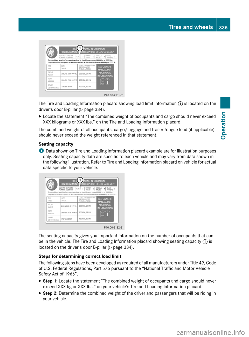
The Tire and Loading Information placard showing load limit information : is located on the
driver’s door B-pillar ( Y page 334).
XLocate the statement “The combined weight of occupants and cargo should never exceed
XXX kilograms or XXX lbs.” on the Tire and Loading Information placard.
The combined weight of all occupants, cargo/luggage and trailer tongue load (if applicable)
should never exceed the weight referenced in that statement.
Seating capacity
i Data shown on Tire and Loading Information placard example are for illustration purposes
only. Seating capacity data are specific to each vehicle and may vary from data shown in
the following illustration. Refer to Tire and Loading Information placard on vehicle for actual
data specific to your vehicle.
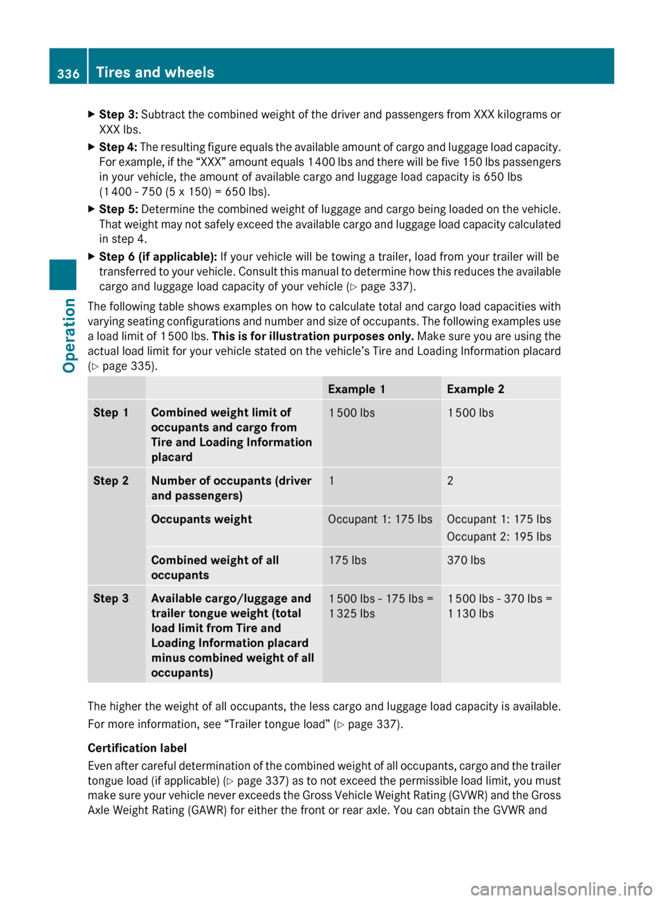
The seating capacity gives you important information on the number of occupants that can
be in the vehicle. The Tire and Loading Information placard showing seating capacity : is
located on the driver’s door B-pillar ( Y page 334).
Steps for determining correct load limit
The following steps have been developed as required of all manufacturers under Title 49, Code
of U.S. Federal Regulations, Part 575 pursuant to the “National Traffic and Motor Vehicle
Safety Act of 1966”.
XStep 1: Locate the statement “The combined weight of occupants and cargo should never
exceed XXX kg or XXX lbs.” on your vehicle’s Tire and Loading Information placard.XStep 2: Determine the combined weight of the driver and passengers that will be riding in
your vehicle.Tires and wheels335OperationBA 197 USA, CA Edition A 2011; 1; 27, en-UShereepeVersion: 3.0.3.52010-03-24T15:31:10+01:00 - Seite 335Z
Page 338 of 436
XStep 3: Subtract the combined weight of the driver and passengers from XXX kilograms or
XXX lbs.XStep 4: The resulting figure equals the available amount of cargo and luggage load capacity.
For example, if the “XXX” amount equals 1 400 lbs and there will be five 150 lbs passengers
in your vehicle, the amount of available cargo and luggage load capacity is 650 lbs
(1 400 - 750 (5 x 150) = 650 lbs).XStep 5: Determine the combined weight of luggage and cargo being loaded on the vehicle.
That weight may not safely exceed the available cargo and luggage load capacity calculated
in step 4.XStep 6 (if applicable): If your vehicle will be towing a trailer, load from your trailer will be
transferred to your vehicle. Consult this manual to determine how this reduces the available
cargo and luggage load capacity of your vehicle ( Y page 337).
The following table shows examples on how to calculate total and cargo load capacities with
varying seating configurations and number and size of occupants. The following examples use
a load limit of 1 500 lbs. This is for illustration purposes only. Make sure you are using the
actual load limit for your vehicle stated on the vehicle’s Tire and Loading Information placard
( Y page 335).
Example 1Example 2Step 1Combined weight limit of
occupants and cargo from
Tire and Loading Information
placard1 500 lbs1 500 lbsStep 2Number of occupants (driver
and passengers)12Occupants weightOccupant 1: 175 lbsOccupant 1: 175 lbs
Occupant 2: 195 lbsCombined weight of all
occupants175 lbs370 lbsStep 3Available cargo/luggage and
trailer tongue weight (total
load limit from Tire and
Loading Information placard
minus combined weight of all
occupants)1 500 lbs - 175 lbs =
1 325 lbs1 500 lbs - 370 lbs =
1 130 lbs
The higher the weight of all occupants, the less cargo and luggage load capacity is available.
For more information, see “Trailer tongue load” ( Y page 337).
Certification label
Even after careful determination of the combined weight of all occupants, cargo and the trailer
tongue load (if applicable) (Y page 337) as to not exceed the permissible load limit, you must
make sure your vehicle never exceeds the Gross Vehicle Weight Rating (GVWR) and the Gross
Axle Weight Rating (GAWR) for either the front or rear axle. You can obtain the GVWR and
336Tires and wheelsOperation
BA 197 USA, CA Edition A 2011; 1; 27, en-UShereepeVersion: 3.0.3.52010-03-24T15:31:10+01:00 - Seite 336
Page 339 of 436
GAWR from the certification label. The certification label can be found on the driver’s door
B-pillar, see the “Technical data” section ( Y page 421).
Gross Vehicle Weight Rating (GVWR): The total weight of the vehicle, all occupants, all cargo,
and the trailer tongue load (if applicable) must never exceed the GVWR.
Gross Axle Weight Rating (GAWR): The total allowable weight that can be carried by a single
axle (front or rear).
To assure that your vehicle does not exceed the maximum permissible weight limits (GVWR
and GAWR for front and rear axle), have the loaded vehicle (including driver, passengers and
all cargo and, if applicable, trailer fully loaded) weighed on a suitable commercial scale.
Trailer tongue load
The tongue load of any trailer is an important weight to measure because it affects the load
you can carry in your vehicle. If a trailer is towed, the tongue load must be added to the weight
of all occupants riding and any cargo you are carrying in the vehicle. The tongue load typically
is 10% of the trailer weight and everything loaded in it.
Your Mercedes-Benz has been designed primarily to carry passengers and their cargo.
Mercedes-Benz does not recommend trailer towing with your vehicle.Maximum tire loadGWarning!
Do not overload the tires by exceeding the
specified load limit as indicated on the Tire
and Loading Information placard on the
driver’s door B-pillar. Overloading the tires
can overheat them, possibly causing a
blowout. Overloading the tires can also result
in handling or steering problems, or brake
failure.
i For illustration purposes only. Actual data
on tires are specific to each vehicle and
may vary from data shown in above
illustration.
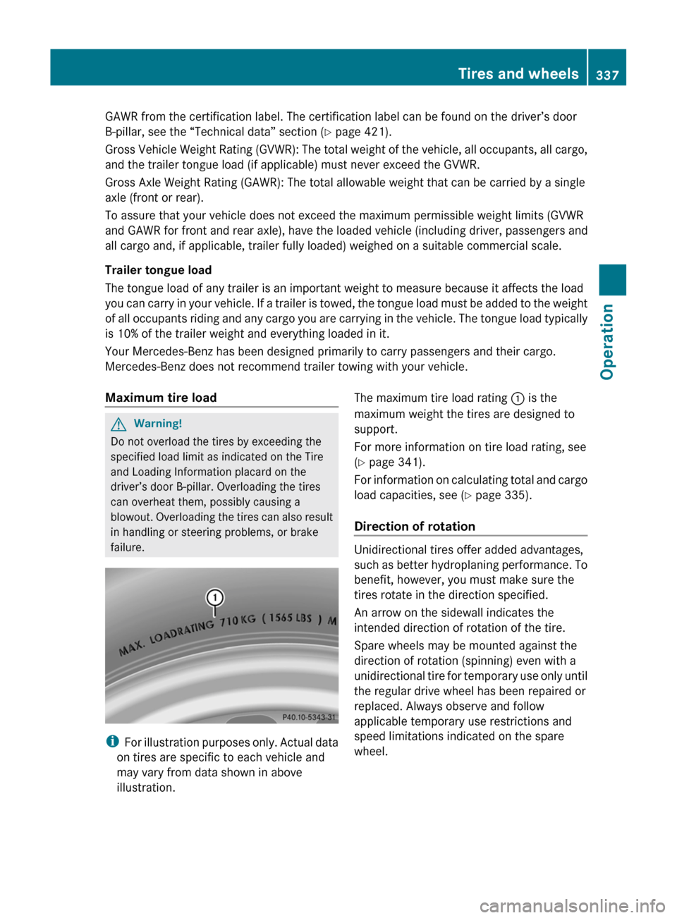
The maximum tire load rating : is the
maximum weight the tires are designed to
support.
For more information on tire load rating, see
( Y page 341).
For information on calculating total and cargo
load capacities, see ( Y page 335).
Direction of rotation
Unidirectional tires offer added advantages,
such as better hydroplaning performance. To
benefit, however, you must make sure the
tires rotate in the direction specified.
An arrow on the sidewall indicates the
intended direction of rotation of the tire.
Spare wheels may be mounted against the
direction of rotation (spinning) even with a
unidirectional tire for temporary use only until
the regular drive wheel has been repaired or
replaced. Always observe and follow
applicable temporary use restrictions and
speed limitations indicated on the spare
wheel.
Tires and wheels337OperationBA 197 USA, CA Edition A 2011; 1; 27, en-UShereepeVersion: 3.0.3.52010-03-24T15:31:10+01:00 - Seite 337Z
Page 347 of 436
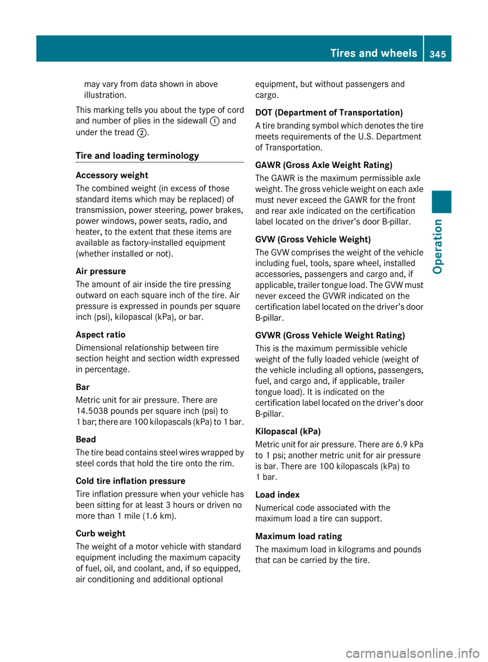
may vary from data shown in above
illustration.
This marking tells you about the type of cord
and number of plies in the sidewall : and
under the tread ;.
Tire and loading terminology
Accessory weight
The combined weight (in excess of those
standard items which may be replaced) of
transmission, power steering, power brakes,
power windows, power seats, radio, and
heater, to the extent that these items are
available as factory-installed equipment
(whether installed or not).
Air pressure
The amount of air inside the tire pressing
outward on each square inch of the tire. Air
pressure is expressed in pounds per square
inch (psi), kilopascal (kPa), or bar.
Aspect ratio
Dimensional relationship between tire
section height and section width expressed
in percentage.
Bar
Metric unit for air pressure. There are
14.5038 pounds per square inch (psi) to
1 bar; there are 100 kilopascals (kPa) to 1 bar.
Bead
The tire bead contains steel wires wrapped by
steel cords that hold the tire onto the rim.
Cold tire inflation pressure
Tire inflation pressure when your vehicle has
been sitting for at least 3 hours or driven no
more than 1 mile (1.6 km).
Curb weight
The weight of a motor vehicle with standard
equipment including the maximum capacity
of fuel, oil, and coolant, and, if so equipped,
air conditioning and additional optional
equipment, but without passengers and
cargo.
DOT (Department of Transportation)
A tire branding symbol which denotes the tire
meets requirements of the U.S. Department
of Transportation.
GAWR (Gross Axle Weight Rating)
The GAWR is the maximum permissible axle
weight. The gross vehicle weight on each axle
must never exceed the GAWR for the front
and rear axle indicated on the certification
label located on the driver’s door B-pillar.
GVW (Gross Vehicle Weight)
The GVW comprises the weight of the vehicle
including fuel, tools, spare wheel, installed
accessories, passengers and cargo and, if
applicable, trailer tongue load. The GVW must
never exceed the GVWR indicated on the
certification label located on the driver’s door
B-pillar.
GVWR (Gross Vehicle Weight Rating)
This is the maximum permissible vehicle
weight of the fully loaded vehicle (weight of
the vehicle including all options, passengers,
fuel, and cargo and, if applicable, trailer
tongue load). It is indicated on the
certification label located on the driver’s door
B-pillar.
Kilopascal (kPa)
Metric unit for air pressure. There are 6.9 kPa
to 1 psi; another metric unit for air pressure
is bar. There are 100 kilopascals (kPa) to
1 bar.
Load index
Numerical code associated with the
maximum load a tire can support.
Maximum load rating
The maximum load in kilograms and pounds
that can be carried by the tire.Tires and wheels345OperationBA 197 USA, CA Edition A 2011; 1; 27, en-UShereepeVersion: 3.0.3.52010-03-24T15:31:10+01:00 - Seite 345Z
Page 348 of 436
Maximum loaded vehicle weight
The sum of curb weight, accessory weight,
total load limit, and production options
weight.
Maximum permissible tire inflation
pressure
This number is the greatest amount of air
pressure that should ever be put in the tire.
Normal occupant weight
The number of occupants the vehicle is
designed to seat, multiplied by 68 kilograms
(150 lb).
Occupant distribution
The distribution of occupants in a vehicle at
their designated seating positions.
Production options weight
The combined weight of those installed
regular production options weighing over
5 lbs (2.3 kilograms) in excess of those
standard items which they replace, not
previously considered in curb weight or
accessory weight, including heavy duty
brakes, ride levelers, roof rack, heavy duty
battery, and special trim.
PSI (Pounds per square inch)
A standard unit of measure for air pressure.
Recommended tire inflation pressure
The recommended tire inflation pressure for
normal driving conditions is listed on the Tire
and Loading Information placard located on
the driver’s door B-pillar. It provides best
handling, tread life and riding comfort.
Supplemental information pertaining to
special driving situations can be found on the
tire inflation pressure label on the inside of
the fuel filler flap.
Rim
A metal support for a tire or a tire and tube
assembly upon which the tire beads are
seated.Sidewall
The portion of a tire between the tread and
the bead.
TIN (Tire Identification Number)
Unique identifier which facilitates efforts by
tire manufacturers to notify purchasers in
recall situations or other safety matters
concerning tires and gives purchasers the
means to easily identify such tires. The TIN is
comprised of “Manufacturer’s identification
mark”, “Tire size”, “Tire type code” and “Date
of manufacture”.
Tire ply composition and material used
This indicates the number of plies or the
number of layers of rubber-coated fabric in
the tire tread and sidewall. Tire
manufacturers also must indicate the ply
materials in the tire and sidewall, which
include steel, nylon, polyester, and others.
Tire speed rating
Part of tire designation (speed symbol);
indicates the speed range for which a tire is
approved.
Total load limit
Rated cargo and luggage load plus
68 kilograms (150 lb) times the vehicle’s
designated seating capacity.
Traction
The adhesive friction of a tire on a surface on
which it moves. The amount of grip provided.
Tread
The portion of a tire that comes into contact
with the road.
Treadwear indicators
Narrow bands, sometimes called “wear bars”
that show across the tread of a tire when
only 1
/ 16 in (1.6 mm) of tread remains.
Uniform Tire Quality Grading Standards
A tire information system that provides
consumers with ratings for a tire’s traction,
temperature and treadwear. Ratings are346Tires and wheelsOperation
BA 197 USA, CA Edition A 2011; 1; 27, en-UShereepeVersion: 3.0.3.52010-03-24T15:31:10+01:00 - Seite 346
Page 349 of 436
determined by tire manufacturers using U.S.
government testing procedures. The ratings
are molded into the sidewall of the tire.
Vehicle maximum load on the tire
Load on an individual tire that is determined
by distributing to each axle its share of the
maximum loaded vehicle weight and dividing
it by two.
Winter driving
General information
Have your vehicle winterized at an authorized
Mercedes-Benz Center.
Winter tires
Always use winter tires at temperatures
below 45‡ (7†) and whenever wintry road
conditions prevail. Not all M+S rated tires
provide special winter performance. Make
sure the tires you use show the mountain/
snowflake imarking on the tire sidewall.
These tires meet specific snow traction
performance requirements of the Rubber
Manufacturers Association (RMA) and the
Rubber Association of Canada (RAC) and
have been designed specifically for use in
snow conditions. Use of winter tires is the
only way to achieve the maximum
effectiveness of your vehicle’s driving safety
systems such as the ABS and the ESC in
winter operation.
For safe handling, make sure all mounted
winter tires are of the same make and have
the same tread design.
GWarning!
Winter tires with a tread depth of less than 1
/ 6
in (4 mm) must be replaced. They are no
longer suitable for winter operation.
For information on winter tires for your
vehicle model, see the “Technical data”
section ( Y page 424).
Always observe the speed rating of the winter
tires installed on your vehicle.
After installing winter tires:XCheck the tire inflation pressure and adjust
it if necessary ( Y page 329).XRestart the Advanced Tire Pressure
Monitoring System ( Y page 329).
i
Vehicle speeds of up to 149 mph
(240 km/h) with winter tires of version 1:
As opposed to the information given on the
tire inflation pressure label on the inside of
the fuel filler flap, the tire inflation pressure
can be reduced by
R front -30 kPa (0.3 bar, 4 psi)
R rear -90 kPa (0.6 bar, 9 psi)
The continuous-travel comfort increases
while the fuel consumption may be
increased slightly.
Snow chains
! Some tire sizes do not leave adequate
clearance for snow chains. To help avoid
serious damage to your vehicle or tires,
make sure the use of snow chains is
permissible as specified in the “Technical
data” section of this Operator’s Manual.
Snow chains should only be driven on snow-
covered roads at speeds not to exceed
30 mph (50 km/h). Remove chains as soon
as possible when driving on roads without
snow.
Observe the following guidelines when using
snow chains:
R Use of snow chains is not permissible with
all wheel/tire combinations ( Y page 424).
R Use snow chains in pairs and on rear
wheels only. Follow the manufacturer’s
mounting instructions.
! If snow chains are mounted to the front
wheels, they may scrape against the body
or axle components. The tires or the vehicle
could be damaged as a result.
Winter driving347OperationBA 197 USA, CA Edition A 2011; 1; 27, en-UShereepeVersion: 3.0.3.52010-03-24T15:31:10+01:00 - Seite 347Z
Page 367 of 436
Text messages
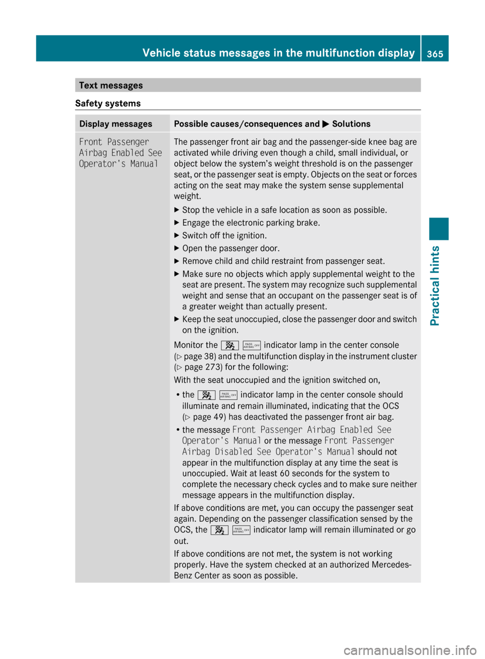
Safety systemsDisplay messagesPossible causes/consequences and M SolutionsFront Passenger
Airbag Enabled See
Operator's ManualThe passenger front air bag and the passenger-side knee bag are
activated while driving even though a child, small individual, or
object below the system’s weight threshold is on the passenger
seat, or the passenger seat is empty. Objects on the seat or forces
acting on the seat may make the system sense supplemental
weight. XStop the vehicle in a safe location as soon as possible.XEngage the electronic parking brake.XSwitch off the ignition.XOpen the passenger door.XRemove child and child restraint from passenger seat.XMake sure no objects which apply supplemental weight to the
seat are present. The system may recognize such supplemental
weight and sense that an occupant on the passenger seat is of
a greater weight than actually present.XKeep the seat unoccupied, close the passenger door and switch
on the ignition.
Monitor the 4 5 indicator lamp in the center console
( Y page 38) and the multifunction display in the instrument cluster
( Y page 273) for the following:
With the seat unoccupied and the ignition switched on,
R the 4 5 indicator lamp in the center console should
illuminate and remain illuminated, indicating that the OCS
( Y page 49) has deactivated the passenger front air bag.
R the message Front Passenger Airbag Enabled See
Operator's Manual or the message Front Passenger
Airbag Disabled See Operator's Manual should not
appear in the multifunction display at any time the seat is
unoccupied. Wait at least 60 seconds for the system to
complete the necessary check cycles and to make sure neither
message appears in the multifunction display.
If above conditions are met, you can occupy the passenger seat
again. Depending on the passenger classification sensed by the
OCS, the 4 5 indicator lamp will remain illuminated or go
out.
If above conditions are not met, the system is not working
properly. Have the system checked at an authorized Mercedes-
Benz Center as soon as possible.
Vehicle status messages in the multifunction display365Practical hintsBA 197 USA, CA Edition A 2011; 1; 27, en-UShereepeVersion: 3.0.3.52010-03-24T15:31:10+01:00 - Seite 365Z
Page 368 of 436
GWarning!
If the 4 5 indicator lamp remains out even after performing the above corrective steps,
do not have any children 12 years old and under and other small individuals use the passenger
seat until the system has been repaired.
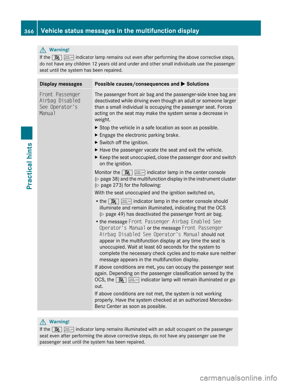
Display messagesPossible causes/consequences and M SolutionsFront Passenger
Airbag Disabled
See Operator's
ManualThe passenger front air bag and the passenger-side knee bag are
deactivated while driving even though an adult or someone larger
than a small individual is occupying the passenger seat. Forces
acting on the seat may make the system sense a decrease in
weight.XStop the vehicle in a safe location as soon as possible.XEngage the electronic parking brake.XSwitch off the ignition.XHave the passenger vacate the seat and exit the vehicle.XKeep the seat unoccupied, close the passenger door and switch
on the ignition.
Monitor the 4 5 indicator lamp in the center console
( Y page 38) and the multifunction display in the instrument cluster
( Y page 273) for the following:
With the seat unoccupied and the ignition switched on,
R the 4 5 indicator lamp in the center console should
illuminate and remain illuminated, indicating that the OCS
( Y page 49) has deactivated the passenger front air bag.
R the message Front Passenger Airbag Enabled See
Operator's Manual or the message Front Passenger
Airbag Disabled See Operator's Manual should not
appear in the multifunction display at any time the seat is
unoccupied. Wait at least 60 seconds for the system to
complete the necessary check cycles and to make sure neither
message appears in the multifunction display.
If above conditions are met, you can occupy the passenger seat
again. Depending on the passenger classification sensed by the
OCS, the 4 5 indicator lamp will remain illuminated or go
out.
If above conditions are not met, the system is not working
properly. Have the system checked at an authorized Mercedes-
Benz Center as soon as possible.
GWarning!
If the 4 5 indicator lamp remains illuminated with an adult occupant on the passenger
seat even after performing the above corrective steps, do not have any passenger use the
passenger seat until the system has been repaired.
366Vehicle status messages in the multifunction displayPractical hints
BA 197 USA, CA Edition A 2011; 1; 27, en-UShereepeVersion: 3.0.3.52010-03-24T15:31:10+01:00 - Seite 366