2011 MERCEDES-BENZ SLS lock
[x] Cancel search: lockPage 405 of 436
GWarning!
Keep TIREFIT out of reach of children. If
swallowed, rinse mouth immediately with
plenty of water and drink plenty of water.
Do not induce vomiting!
Consult a physician immediately.
iIf sealant has leaked out, let it dry. You
can then peel it off.
If clothing has come in contact with
TIREFIT, have it dry-cleaned with
perchloroethylene as soon as possible.
GWarning!
Observe safety instructions on air pump label.
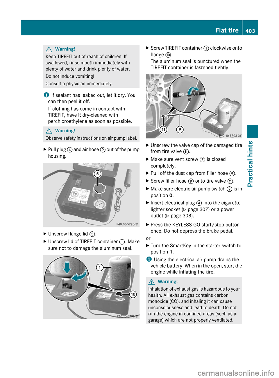
XPull plug ? and air hose E out of the pump
housing.
XUnscrew flange lid A.XUnscrew lid of TIREFIT container :. Make
sure not to damage the aluminum seal.
XScrew TIREFIT container : clockwise onto
flange F.
The aluminum seal is punctured when the
TIREFIT container is fastened tightly.
XUnscrew the valve cap of the damaged tire
from tire valve G.
XMake sure vent screw C is closed
completely.
XPull off the dust cap from filler hose E.XScrew filler hose E onto tire valve G.XMake sure electric air pump switch ; is in
position 0.
XInsert electrical plug ? into the cigarette
lighter socket (Y page 307) or a power
outlet (Y page 308).
XPress the KEYLESS-GO start/stop button
once. Do not depress the brake pedal.
or
XTurn the SmartKey in the starter switch to
position 1.
iUsing the electrical air pump drains the
vehicle battery. When in the open, start the
engine while inflating the tire.
GWarning!
Inhalation of exhaust gas is hazardous to your
health. All exhaust gas contains carbon
monoxide (CO), and inhaling it can cause
unconsciousness and lead to death. Do not
run the engine in confined areas (such as a
garage) which are not properly ventilated.
Flat tire403Practical hintsBA 197 USA, CA Edition A 2011; 1; 27, en-UShereepeVersion: 3.0.3.52010-03-24T15:31:10+01:00 - Seite 403Z
Page 408 of 436

Rcollapsible wheel chock
Rjack
Rwheel wrench
Ralignment bolt
For information on where to find the
respective items, see “Where will I find ...?”
(Y page 362).
XPrevent the vehicle from rolling away by
blocking wheels with wheel chocks or other
sizeable objects.
One wheel chock is included with the
vehicle tool kit (Y page 362). For
information on setting up a collapsible
wheel chock, see (Y page 363).
GWarning!
Only jack up the vehicle on level ground or on
slight inclines/declines. Otherwise, the
vehicle could fall off the jack and injure you or
others.
Changing a wheel on a level surface
Changing rear wheel on passenger side (exampleillustration)
XPlace a wheel chock or other sizeable
object in front of and another wheel chock
or other sizeable object behind the wheel
that is diagonally opposite to the wheel
being changed.
Changing a wheel on a slight decline
Always try lifting the vehicle using the jack on
a level surface. However, should
circumstances require you to do so on a slight
decline:
Changing wheel on passenger side (exampleillustration)
XPlace wheel chocks or other sizeable
objects on the downhill side in front of both
wheels on the side opposite to the side on
which the wheel is to be changed.
Changing a wheel on a slight incline
Always try lifting the vehicle using the jack on
a level surface. However, should
circumstances require you to do so on a slight
incline:
Changing wheel on passenger side (exampleillustration)
XPlace wheel chocks or other sizeable
objects on the downhill side in front of both
wheels on the side opposite to the side on
which the wheel is to be changed.
406Wheel changePractical hints
BA 197 USA, CA Edition A 2011; 1; 27, en-UShereepeVersion: 3.0.3.52010-03-24T15:31:10+01:00 - Seite 406
Page 409 of 436
Removing the wheelGWarning!
When jacking up the vehicle, only use the jack
which has been specifically approved by
Mercedes-Benz for your vehicle.
The jack is designed exclusively for jacking up
the vehicle at the jack take-up brackets built
into both sides of the vehicle. Make sure the
jack arm is fully seated in the jack take-up
bracket. The jack must always be vertical
when in use, especially on inclines or
declines.
The jack is intended only for lifting the vehicle
briefly for wheel changes. It is not suited for
performing maintenance work under the
vehicle. To help avoid personal injury, use the
jack only to lift the vehicle during a wheel
change.
Never get beneath the vehicle while it is
supported by the jack. Keep hands and feet
away from the area under the lifted vehicle.
Always lower the vehicle onto sufficient
capacity jackstands before working under the
vehicle.
Always make sure the electronic parking
brake is engaged. In addition, block the
wheels with wheel chocks or other sizeable
objects before raising the vehicle with the
jack. Do not disengage the electronic parking
brake while the vehicle is raised.
Make sure that the ground on which the
vehicle is standing and where you place the
jack is solid, level and not slippery. If
necessary, use a large underlay. On slippery
surfaces, such as tiled floors, you should use
a non-slip underlay, for example a rubber mat.
Do not use wooden blocks or similar objects
to support the jack. Otherwise the jack may
not be able to achieve its load-bearing
capacity if it is not at its full height.
Never start the engine when the vehicle is
raised.
Also observe the notes on the jack.
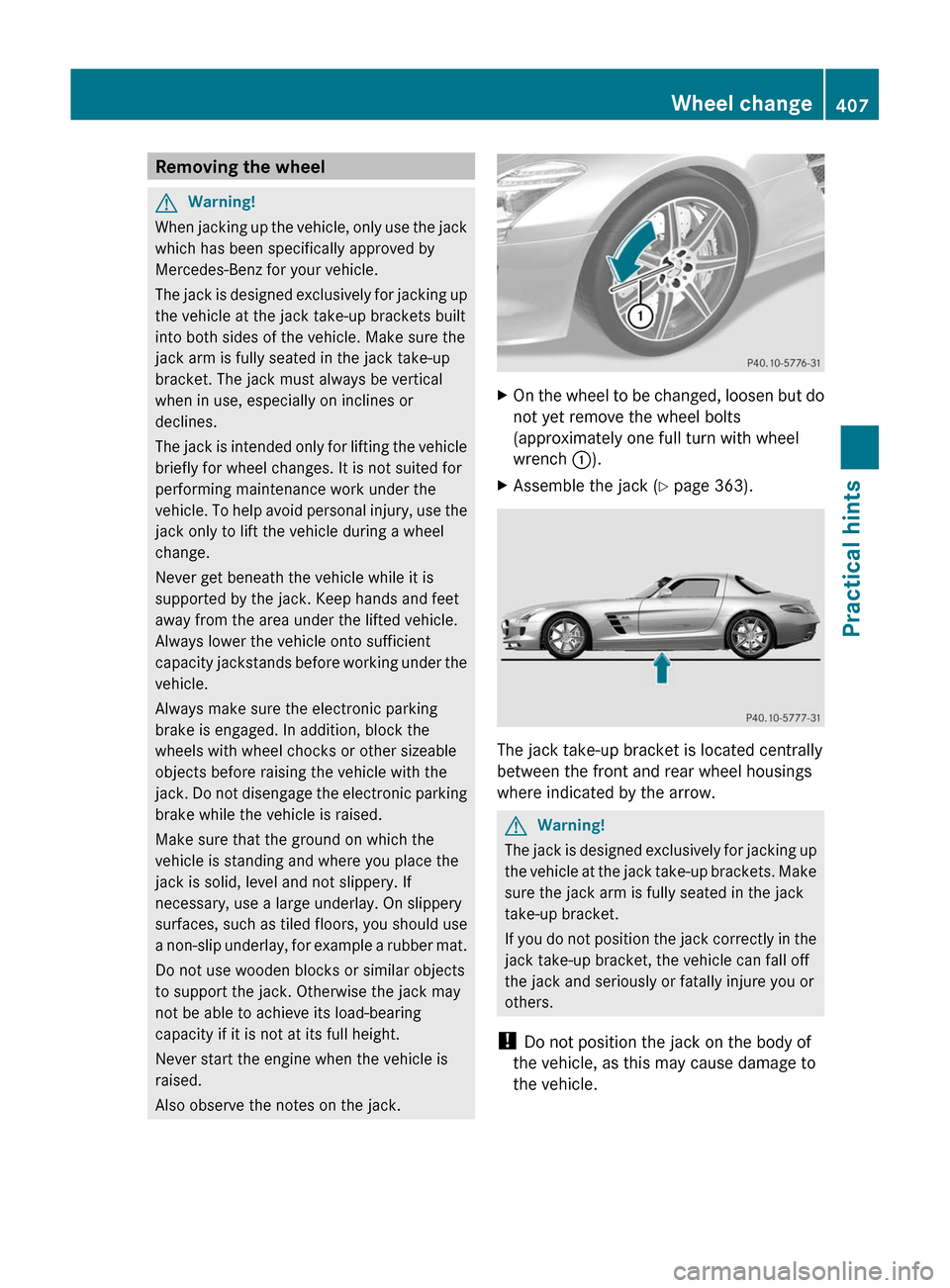
XOn the wheel to be changed, loosen but do
not yet remove the wheel bolts
(approximately one full turn with wheel
wrench :).
XAssemble the jack (Y page 363).
The jack take-up bracket is located centrally
between the front and rear wheel housings
where indicated by the arrow.
GWarning!
The jack is designed exclusively for jacking up
the vehicle at the jack take-up brackets. Make
sure the jack arm is fully seated in the jack
take-up bracket.
If you do not position the jack correctly in the
jack take-up bracket, the vehicle can fall off
the jack and seriously or fatally injure you or
others.
! Do not position the jack on the body of
the vehicle, as this may cause damage to
the vehicle.
Wheel change407Practical hintsBA 197 USA, CA Edition A 2011; 1; 27, en-UShereepeVersion: 3.0.3.52010-03-24T15:31:10+01:00 - Seite 407Z
Page 410 of 436

XPlace jack = on firm ground.XPosition jack = under take-up
bracket ; so that it is always vertical as
seen from the side, even if the vehicle is
parked on an incline.
XTurn crank ? clockwise until jack = is
fully seated in take-up bracket ; and the
jack base evenly meets the ground.
XJack up the vehicle until the wheel is a
maximum of 1.2 in (3 cm) from the ground.
! The rim could strike the ceramic
composite brake disk when removing and
attaching the wheel. The ceramic
composite brake disk could be damaged.
Exercise appropriate care and have a
second person assist you if possible or use
a second alignment bolt.
XUnscrew the uppermost wheel bolt and
remove it.
XReplace this wheel bolt with alignment bolt
A.
XRemove the remaining bolts.
! Do not place wheel bolts in sand or dirt.
This could result in damage to the wheel
bolts and wheel hub threads.
XRemove the wheel.
Mounting the wheel
GWarning!
Always replace wheel bolts that are damaged
or rusted.
Never apply oil or grease to wheel bolts.
Damaged wheel hub threads should be
repaired immediately. Do not continue to
drive under these circumstances! Contact an
authorized Mercedes-Benz Center or call
Roadside Assistance.
Incorrect wheel bolts or improperly tightened
wheel bolts can cause the wheel to come off.
This could cause an accident. Make sure to
use the correct wheel bolts.
GWarning!
Only use genuine Mercedes-Benz wheel bolts.
Other wheel bolts may come loose.
Do not tighten the wheel bolts when the
vehicle is raised. Otherwise the vehicle could
fall off the jack.
408Wheel changePractical hints
BA 197 USA, CA Edition A 2011; 1; 27, en-UShereepeVersion: 3.0.3.52010-03-24T15:31:10+01:00 - Seite 408
Page 411 of 436
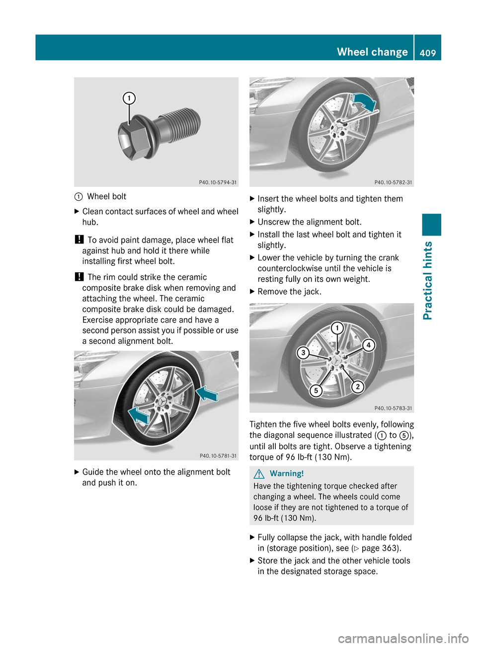
:Wheel boltXClean contact surfaces of wheel and wheel
hub.
! To avoid paint damage, place wheel flat
against hub and hold it there while
installing first wheel bolt.
! The rim could strike the ceramic
composite brake disk when removing and
attaching the wheel. The ceramic
composite brake disk could be damaged.
Exercise appropriate care and have a
second person assist you if possible or use
a second alignment bolt.
XGuide the wheel onto the alignment bolt
and push it on.
XInsert the wheel bolts and tighten them
slightly.
XUnscrew the alignment bolt.XInstall the last wheel bolt and tighten it
slightly.
XLower the vehicle by turning the crank
counterclockwise until the vehicle is
resting fully on its own weight.
XRemove the jack.
Tighten the five wheel bolts evenly, following
the diagonal sequence illustrated (: to A),
until all bolts are tight. Observe a tightening
torque of 96 lb-ft (130 Nm).
GWarning!
Have the tightening torque checked after
changing a wheel. The wheels could come
loose if they are not tightened to a torque of
96 lb-ft (130 Nm).
XFully collapse the jack, with handle folded
in (storage position), see (Y page 363).
XStore the jack and the other vehicle tools
in the designated storage space.
Wheel change409Practical hintsBA 197 USA, CA Edition A 2011; 1; 27, en-UShereepeVersion: 3.0.3.52010-03-24T15:31:10+01:00 - Seite 409Z
Page 413 of 436
Do not rub the battery with rags or cloths. The
battery could explode if touched due to
electrostatic charge or due to spark
formation.
! The battery is a Valve-Regulated Lead
Acid (VRLA) battery, also referred to as
“fleece” battery.
Such batteries do not require topping-up of
the electrolyte level. VRLA batteries
therefore do not have cell caps and the
battery cover is non-removable. Do not
attempt to open the battery as otherwise
the battery will be damaged.
VRLA batteries do not require topping-up of
the electrolyte level. They cannot be
opened to check the electrolyte level.
However, the battery condition must be
checked periodically by performing a
battery conductance test. Refer to
Maintenance Booklet for battery condition
testing intervals.
The factory-equipped battery may only be
replaced with a battery that
Rhas the same security features
Ris of identical size
Ris of identical voltage
Ris of identical capacity
! As any other battery, the battery may
discharge if you do not operate the vehicle
for an extended period of time. Have the
battery disconnected at a qualified
workshop or an authorized Mercedes-Benz
Center in such a case. You may also
connect an accessory battery charge unit
expressly approved by Mercedes-Benz for
your vehicle model to maintain the battery
charge. Contact an authorized Mercedes-
Benz Center for further information.
The battery, the battery ventilation hose
and the lateral plug must always be
securely installed when the vehicle is in
operation.
! Never loosen or detach battery terminal
clamps while the engine is running or the
SmartKey is in the starter switch or
KEYLESS-GO button is in position 1.
Otherwise the alternator and other
electronic components could be severely
damaged.
Have the battery checked regularly at an
authorized Mercedes-Benz Center.
Refer to Maintenance Booklet for
maintenance intervals or contact an
authorized Mercedes-Benz Center for
further information.
iMake sure the vehicle’s on-board
electronics have status 0 when you turn off
the engine and no longer require any
electrical consumers. The vehicle then
uses very little power and the battery is
spared.
iIf the battery is discharged, you must use
the mechanical key to unlock the vehicle.
iAfter battery power was interrupted, do
the following:
RSynchronize the power windows
(Y page 256).
RSynchronize the exterior rear view
mirrors (Y page 248).
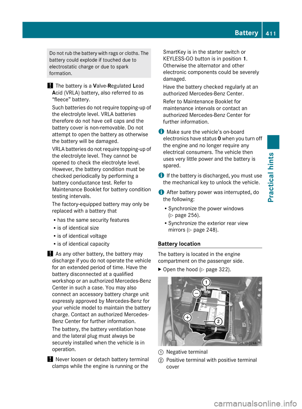
Battery location
The battery is located in the engine
compartment on the passenger side.
XOpen the hood (Y page 322).:Negative terminal;Positive terminal with positive terminal
cover
Battery411Practical hintsBA 197 USA, CA Edition A 2011; 1; 27, en-UShereepeVersion: 3.0.3.52010-03-24T15:31:10+01:00 - Seite 411Z
Page 418 of 436
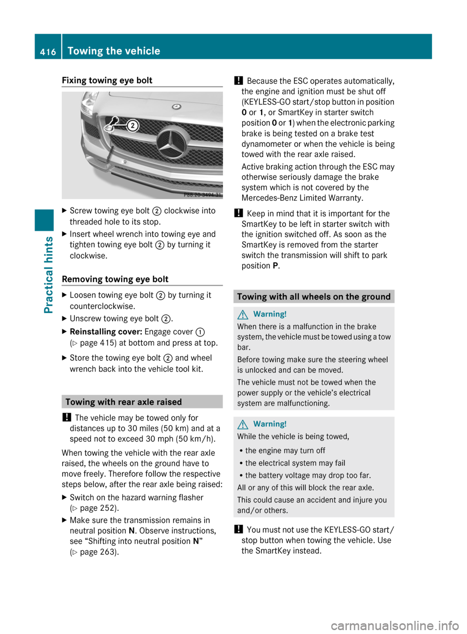
Fixing towing eye boltXScrew towing eye bolt ; clockwise into
threaded hole to its stop.XInsert wheel wrench into towing eye and
tighten towing eye bolt ; by turning it
clockwise.
Removing towing eye bolt
XLoosen towing eye bolt ; by turning it
counterclockwise.XUnscrew towing eye bolt ;.XReinstalling cover: Engage cover :
( Y page 415) at bottom and press at top.XStore the towing eye bolt ; and wheel
wrench back into the vehicle tool kit.
Towing with rear axle raised
! The vehicle may be towed only for
distances up to 30 miles (50 km) and at a
speed not to exceed 30 mph (50 km/h).
When towing the vehicle with the rear axle
raised, the wheels on the ground have to
move freely. Therefore follow the respective
steps below, after the rear axle being raised:
XSwitch on the hazard warning flasher
( Y page 252).XMake sure the transmission remains in
neutral position N. Observe instructions,
see “Shifting into neutral position N”
( Y page 263).!
Because the ESC operates automatically,
the engine and ignition must be shut off
(KEYLESS-GO start/stop button in position
0 or 1, or SmartKey in starter switch
position 0 or 1) when the electronic parking
brake is being tested on a brake test
dynamometer or when the vehicle is being
towed with the rear axle raised.
Active braking action through the ESC may
otherwise seriously damage the brake
system which is not covered by the
Mercedes-Benz Limited Warranty.
! Keep in mind that it is important for the
SmartKey to be left in starter switch with
the ignition switched off. As soon as the
SmartKey is removed from the starter
switch the transmission will shift to park
position P.
Towing with all wheels on the ground
GWarning!
When there is a malfunction in the brake
system, the vehicle must be towed using a tow
bar.
Before towing make sure the steering wheel
is unlocked and can be moved.
The vehicle must not be towed when the
power supply or the vehicle’s electrical
system are malfunctioning.
GWarning!
While the vehicle is being towed,
R the engine may turn off
R the electrical system may fail
R the battery voltage may drop too far.
All or any of this will block the rear axle.
This could cause an accident and injure you
and/or others.
! You must not use the KEYLESS-GO start/
stop button when towing the vehicle. Use
the SmartKey instead.
416Towing the vehiclePractical hints
BA 197 USA, CA Edition A 2011; 1; 27, en-UShereepeVersion: 3.0.3.52010-03-24T15:31:10+01:00 - Seite 416
Page 423 of 436
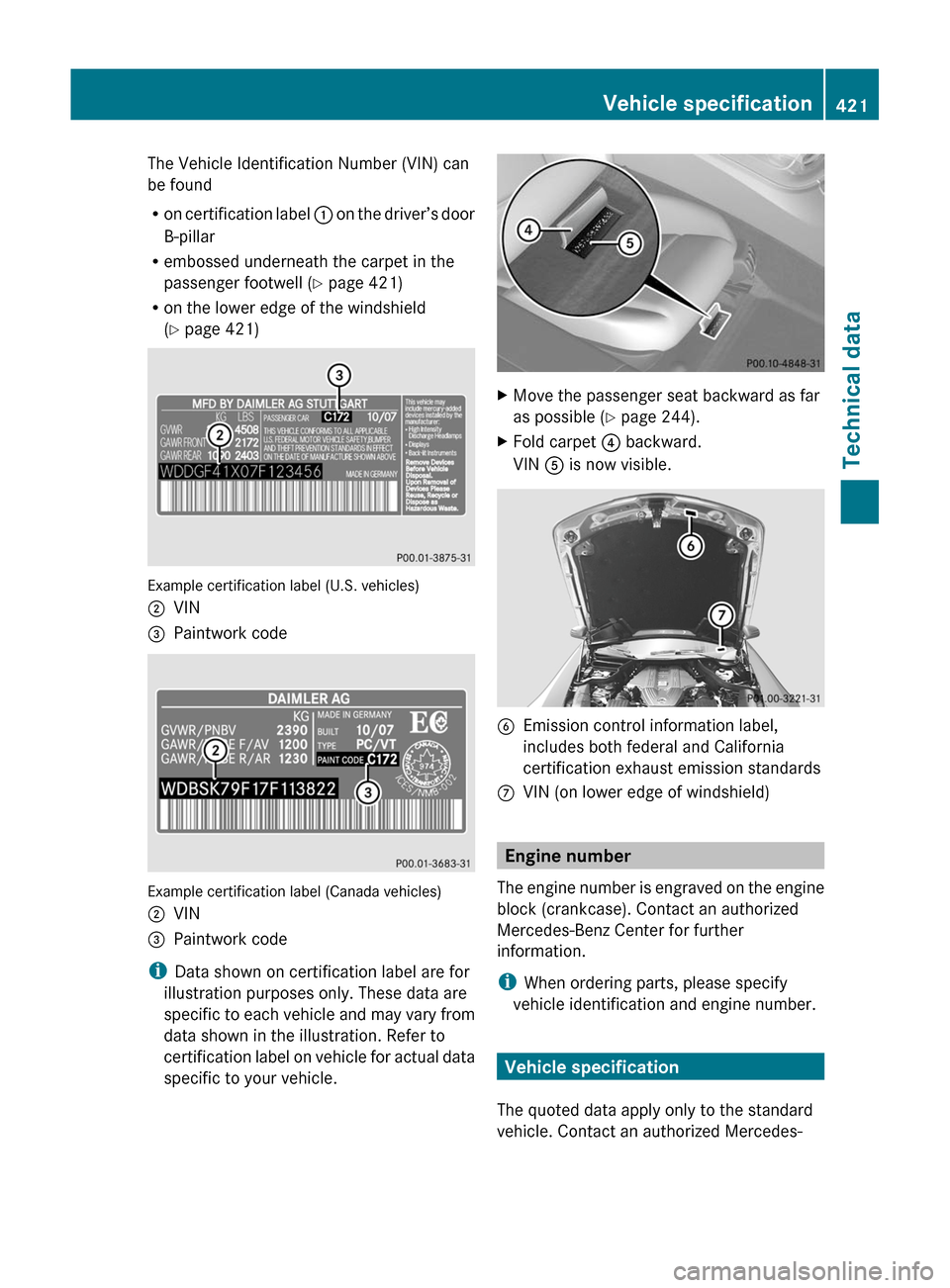
The Vehicle Identification Number (VIN) can
be found
R on certification label : on the driver’s door
B-pillar
R embossed underneath the carpet in the
passenger footwell ( Y page 421)
R on the lower edge of the windshield
( Y page 421)
Example certification label (U.S. vehicles)
;VIN=Paintwork code
Example certification label (Canada vehicles)
;VIN=Paintwork code
i
Data shown on certification label are for
illustration purposes only. These data are
specific to each vehicle and may vary from
data shown in the illustration. Refer to
certification label on vehicle for actual data
specific to your vehicle.
XMove the passenger seat backward as far
as possible ( Y page 244). XFold carpet ? backward.
VIN A is now visible.BEmission control information label,
includes both federal and California
certification exhaust emission standardsCVIN (on lower edge of windshield)
Engine number
The engine number is engraved on the engine
block (crankcase). Contact an authorized
Mercedes-Benz Center for further
information.
i When ordering parts, please specify
vehicle identification and engine number.
Vehicle specification
The quoted data apply only to the standard
vehicle. Contact an authorized Mercedes-
Vehicle specification421Technical dataBA 197 USA, CA Edition A 2011; 1; 27, en-UShereepeVersion: 3.0.3.52010-03-24T15:31:10+01:00 - Seite 421