2011 MERCEDES-BENZ S-Class Starting the car
[x] Cancel search: Starting the carPage 315 of 524

Problems with the transmissionProblemPossible causes/consequences and M SolutionsThe acceleration ability
is deteriorating.
The transmission no
longer changes gear.The transmission is in emergency mode.
It is only possible to shift into 2nd gear and reverse gear.XStop the vehicle.XShift the transmission to position P.XSwitch off the engine.XWait at least 10 seconds before restarting the engine.XShift the transmission to position D or R.
If D is selected, the transmission shifts into 2nd gear; if R is
selected, the transmission shifts into reverse gear.XHave the transmission checked at a qualified specialist
workshop immediately.Transfer case
This section is only valid for vehicles with 4-
wheel drive (4MATIC). Power is always
transmitted to both axles.
! Performance tests may only be carried
out on a 2-axle dynamometer. The brake
system or transfer case could otherwise be
damaged. Contact an authorized
Mercedes-Benz Center for a performance
test. Mercedes-Benz recommends that you
use an authorized Mercedes-Benz Center
for this purpose.
! To prevent ESP ®
from intervening, the
ignition must be switched off (SmartKey or
the Start/Stop button in position 0 or 1) if:
R the electric parking brake is being tested
on a brake dynamometer.
R the vehicle is being towed with only one
axle raised (not permitted for vehicles
with 4MATIC).
The brake system could otherwise be
damaged.Refueling
Important safety notes
GWarning
Gasoline is highly flammable and poisonous.
It burns violently and can cause serious
personal injury.
Never allow sparks, flames or smoking
materials near gasoline.
Turn off the engine before refueling.
Whenever you are around gasoline, avoid
inhaling fumes and any skin or clothing
contact.
Direct skin contact with fuels and the
inhalation of fuel vapors are damaging to your
health.
GWarning
Overfilling of the fuel tank may create
pressure in the system which could cause a
gas discharge. This could cause the gasoline
to spray back out when removing the fuel
pump nozzle, which could cause personal
injury.
Refueling313Driving and parkingZ
Page 394 of 524
Display messagesPossible causes/consequences and M SolutionsThe yellow F (USA only)/ ! (Canada only) warning lamp
lights up. The red F (USA only)/ ! (Canada only) indicator
lamp flashes for approximately 10 seconds after the electric
parking brake has been applied or released. It then goes out or
remains lit.
The electric parking brake is malfunctioning, e.g. because of over
or undervoltage.XPull away carefully.XVisit a qualified specialist workshop.
In the event of over or undervoltage:
XRemove the cause for the over or undervoltage, e.g. by charging
the battery or restarting the engine.XSwitch the ignition off and on, and then apply or release the
electric parking brake.
If this does not release the electric parking brake:
XDo not drive on.XConsult a qualified specialist workshop.The yellow F (USA only)/ ! (Canada only) warning lamp
lights up. The red F (USA only)/ ! (Canada only) indicator
lamp flashes for approximately 10 seconds after the electric
parking brake has been applied or released. It then goes out or
remains lit.
The electric parking brake has overheated.XAllow the vehicle to cool down. Do not apply or release the
electric parking brake during this time.XUse the folding wheel chock (Y page 464) from the vehicle tool
kit to secure the vehicle against rolling away.XWhen the vehicle has cooled down: switch the ignition off and
on again, then apply or release the electric parking brake.392Display messagesOn-board computer and displays
Page 437 of 524

pressed the SOS button. Carefully leave the
vehicle and move to a safe location. The
Response Center will automatically contact
local emergency officials with the vehicle's
approximate location if they receive an
automatic SOS signal and cannot make voice
contact with the vehicle occupants.
Roadside Assistance call buttonXOpen the stowage compartment under the
armrest ( Y page 423).XPress and hold Roadside Assistance
button : for more than two seconds.
A call to a Mercedes-Benz Roadside
Assistance Representative is initiated. The
indicator lamp in Roadside Assistance
button : flashes while the call is active.
The Connecting Call message appears in
the COMAND display and COMAND is
muted.
If a connection can be established, the Call
Connected message appears in the
COMAND display.
If a mobile phone network is available and
there is sufficient GPS reception, the mbrace
system transmits data to the Response
Center, for example:
R current location of the vehicle
R vehicle identification number
R vehicle model
R vehicle color
i The COMAND display shows that an
mbrace call is active. You can switch to the
navigation menu by pressing the
S button on COMAND during the call.
Spoken commands are not available.
A voice connection is established between
the Mercedes-Benz Roadside Assistance
Representative and the vehicle occupants.XDescribe the type of assistance needed.
The Mercedes-Benz Roadside Assistance
Representative either sends a qualified
Mercedes-Benz technician or organizes for
your vehicle to be transported to the nearest
authorized Mercedes-Benz Center. You may
be charged for services such as repair work
and/or towing. Further details are available
in your mbrace manual.
i If the indicator lamp in MB info call
button : flashes continuously and it was
not possible to establish a voice
connection to the Response Center, then
the mbrace system has failed to initiate a
Roadside Assistance call (e.g. the
corresponding cellular phone network is
not available). The Call Failed message
appears in the multifunction display.
The COMAND display shows the Call
could not be connected! message.
Press W to confirm the message.
XTo end a call: press the ~ button on the
multifunction steering wheel.
or
XPress the corresponding button for ending
a phone call on the COMAND telephone
keypad.
i Sign and Drive services 30
: you are not
charged for services such as jump-starting,
providing a few gallons of fuel for a fuel tank
that has been run dry or changing a flat tire
with the vehicle's own spare tire.
30 USA only.Features435Loading, stowing and featuresZ
Page 448 of 524
Vehicle equipment
iThis manual describes all the standard
and optional equipment of your vehicle
which was available at the time of
purchase. Country-specific differences are
possible. Note that your vehicle may not be
equipped with all functions described.
Engine compartment
Hood
Opening the hood
GWarning
Do not pull the release lever while the vehicle
is in motion. Otherwise, the hood could be
forced open by passing air flow.
This could cause the hood to come loose and
injure you and/or others.
GWarning
Hybrid vehicles: ensure that you read the
"HYBRID" supplement. You may otherwise fail
to recognize dangers.
GWarning
Do not open the hood when the engine is
overheated. You could be seriously injured.
Observe the coolant temperature gauge to
determine whether the engine may be
overheated. If you see flames or smoke
coming from the engine compartment, move
away from the vehicle. Wait until the engine
has cooled. If necessary, call the fire
department.
GWarning
There is a risk of injury if the hood is open,
even if the engine is not running.
Some engine components can become very
hot.
To avoid the risk of burns, only touch those
components described in the Operator's
Manual and observe the relevant safety notes.
GWarning
To help prevent personal injury, stay clear of
moving parts when the hood is open and the
engine is running.
The radiator fan may continue to run for
approximately 30 seconds or may even
restart after the engine has been turned off.
Stay clear of fan blades.
GWarning
The engine is equipped with a transistorized
ignition system. Because of the high voltage,
it is dangerous to touch any components
(ignition coils, spark plug sockets, diagnostic
socket) of the ignition system:
Rwith the engine running
Rwhile starting the engine
Rwhen the ignition is switched on and the
engine is turned manually
XMake sure that the windshield wipers are
switched off.
GWarning
The windshield wipers and wiper linkage
could be set in motion.
When the hood is open, you or others could
be injured by the wiper linkage.
Make sure that the windshield wipers are
switched off. Remove the SmartKey or make
sure that no ignition position has been
selected with KEYLESS-GO. All indicator
lamps must be off in the instrument cluster.
446Engine compartmentMaintenance and care
Page 472 of 524
The battery, breather hose and cover of the
positive terminal clamp must be installed
securely during operation.
i Remove the key if you park the vehicle
and do not require any electrical
consumers. The vehicle will then use very
little energy, thus conserving battery
power.
Mercedes-Benz recommends that you do not
carry out work on batteries yourself, e.g.
removing, charging or replacing. Always have
this work performed at a qualified specialist
workshop, e.g. an authorized Mercedes-Benz
Center.
Charging the battery
GWarning
Never charge a battery while still installed in
the vehicle unless the accessory battery
charge unit approved by Mercedes-Benz is
being used. Gases may escape during
charging and cause explosions that may
result in paint damage, corrosion or personal
injury.
An accessory battery charge unit specially
adapted for Mercedes-Benz vehicles and
tested and approved by Mercedes-Benz is
available. It permits the charging of the
battery in its installed position. Contact an
authorized Mercedes-Benz Center for
information and availability.
Charge the battery in accordance with the
separate instructions for the accessory
battery charger.
GWarning
There is a risk of acid burns during the
charging process due to the gases which
escape from the battery. Do not lean over the
battery during the charging process.
GWarning
Battery acid is caustic. Avoid contact with the
skin, eyes or clothing.
! Only charge the installed battery with a
battery charger which has been tested and
approved by Mercedes-Benz. These battery
chargers allow the battery to be charged
while still installed.
! Only use battery chargers with a
maximum charging voltage of 14.8 V.
! Only charge the battery using the jump-
starting connection point.
The jump-starting connection point is in the
engine compartment ( Y page 471).XOpen the hood ( Y page 446).XConnect the battery charger to the positive
terminal and earth point in the same order
as when connecting the donor battery in
the jump-starting procedure
( Y page 471).XRead the battery charger's operating
instructions before charging the battery.470BatteryRoadside assistance
Page 476 of 524
Installing/removing the towing eye
Installing the towing eye
XRemove the towing eye from the vehicle
tool kit (Y page 462).
GWarning
The exhaust tail pipe may be hot. You could
burn yourself if you touch the tail pipe. Be
particularly careful when removing the rear
cover.
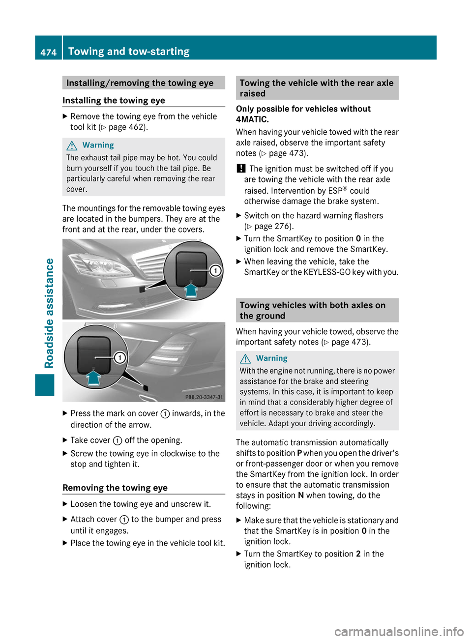
The mountings for the removable towing eyes
are located in the bumpers. They are at the
front and at the rear, under the covers.
XPress the mark on cover : inwards, in the
direction of the arrow.
XTake cover : off the opening.XScrew the towing eye in clockwise to the
stop and tighten it.
Removing the towing eye
XLoosen the towing eye and unscrew it.XAttach cover : to the bumper and press
until it engages.
XPlace the towing eye in the vehicle tool kit.Towing the vehicle with the rear axle
raised
Only possible for vehicles without
4MATIC.
When having your vehicle towed with the rear
axle raised, observe the important safety
notes (Y page 473).
! The ignition must be switched off if you
are towing the vehicle with the rear axle
raised. Intervention by ESP® could
otherwise damage the brake system.
XSwitch on the hazard warning flashers
(Y page 276).
XTurn the SmartKey to position 0 in the
ignition lock and remove the SmartKey.
XWhen leaving the vehicle, take the
SmartKey or the KEYLESS-GO key with you.
Towing vehicles with both axles on
the ground
When having your vehicle towed, observe the
important safety notes (Y page 473).
GWarning
With the engine not running, there is no power
assistance for the brake and steering
systems. In this case, it is important to keep
in mind that a considerably higher degree of
effort is necessary to brake and steer the
vehicle. Adapt your driving accordingly.
The automatic transmission automatically
shifts to position P when you open the driver's
or front-passenger door or when you remove
the SmartKey from the ignition lock. In order
to ensure that the automatic transmission
stays in position N when towing, do the
following:
XMake sure that the vehicle is stationary and
that the SmartKey is in position 0 in the
ignition lock.
XTurn the SmartKey to position 2 in the
ignition lock.
474Towing and tow-startingRoadside assistance
Page 491 of 524

XPress the 9 or : button to select
Tire Pressure .XPress the a button.
The current tire pressure for each wheel will
be displayed in the multifunction display.
If the vehicle has been parked for longer than
20 minutes, the Tire Pressures
Displayed After Driving A Few
Minutes message appears in the display.
After a teach-in period, the tire pressure
monitor automatically recognizes new wheels
or new sensors. As long as a clear allocation
of the tire pressure values to the individual
wheels is not possible, the Tire Pressure
Monitor Active message is shown instead
of the tire pressure display. The tire pressures
are already being monitored.
i If a spare wheel/emergency spare wheel
is mounted, the system may continue to
show the tire pressure of the wheel that has
been removed for a few minutes. If this
occurs, note that the value displayed for
the position where the spare wheel is
mounted is not the same as the spare
wheel/emergency spare wheel's current
tire pressure.
TPMS warning messages
If the tire pressure monitor detects a
significant pressure loss on one or more tires,
a warning message is shown in the
multifunction display. A warning tone also
sounds and the tire pressure warning lamp
lights up in the instrument cluster.
For each tire that is affected by a significant
loss of pressure, the tire pressure is shown in
yellow.
If the Correct Tire Pressure message
appears in the multifunction display:
XCheck the tire pressure on all four wheels
and correct it if necessary.
i If the wheel positions on the vehicle are
interchanged, the tire pressures may be
displayed for the wrong positions for a
short time. This is rectified after a few
minutes of driving, and the tire pressures
are displayed for the correct positions.
Restarting the tire pressure monitorGWarning
It is the driver's responsibility to set the tire
inflation pressure to the recommended cold
tire inflation pressure. Underinflated tires
affect the ability to steer or brake the vehicle.
You might lose control over the vehicle.
When you restart the tire pressure monitor,
all existing warning messages are deleted and
the warning lamps go out. The monitor uses
the currently set tire pressures as the
reference values for monitoring.
The TPMS must be restarted when you set the
tire pressure to a new value (as a result of
changed handling or load characteristics, for
example). The TPMS then monitors the new
tire pressure values.
i Canada only: in most cases, the tire
pressure monitor recognizes the new
reference values automatically. However,
you can also define reference values
manually as described here.
Restart the tire pressure monitor after you
have set the tire pressure to the value
recommended for the desired driving
situation ( Y page 483). Only correct tire
pressures on cold tires. Comply with the
recommended tire pressures on the Tire and
Loading Information placard on the B-pillar on
the driver's side Additional tire pressure
values for driving at high speeds or with heavy
loads can be found in the Tire Pressure table
on the inside of the fuel filler flap.
XMake sure that the tire pressure is correct
on all four wheels.XMake sure that the SmartKey is in position
2 in the ignition lock.XPress the = or ; button to select the
Service menu.Tire pressure489Tires and wheelsZ
Page 501 of 524
In addition to the load bearing index, load
index : may be imprinted after the letters
that identify speed index B (Y page 496) on
the sidewall of the tire.
R If no specification is given: no text (as in the
example above), represents a standard
load (SL) tire
R XL or Extra Load: represents a reinforced
tire
R Light load: represents a light load tire
R C, D, E: represents a load range that
depends on the maximum load that the tire
can carry at a certain pressure
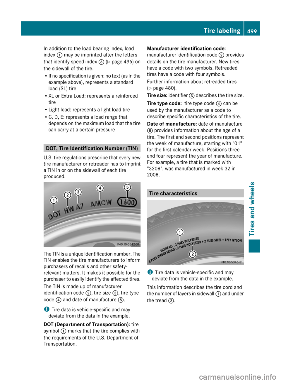
DOT, Tire Identification Number (TIN)
U.S. tire regulations prescribe that every new
tire manufacturer or retreader has to imprint
a TIN in or on the sidewall of each tire
produced.
The TIN is a unique identification number. The
TIN enables the tire manufacturers to inform
purchasers of recalls and other safety-
relevant matters. It makes it possible for the
purchaser to easily identify the affected tires.
The TIN is made up of manufacturer
identification code ;, tire size =, tire type
code ? and date of manufacture A.
i Tire data is vehicle-specific and may
deviate from the data in the example.
DOT (Department of Transportation): tire
symbol : marks that the tire complies with
the requirements of the U.S. Department of
Transportation.
Manufacturer identification code:
manufacturer identification code ; provides
details on the tire manufacturer. New tires
have a code with two symbols. Retreaded
tires have a code with four symbols.
Further information about retreaded tires
( Y page 480).
Tire size: identifier = describes the tire size.
Tire type code: tire type code ? can be
used by the manufacturer as a code to
describe specific characteristics of the tire.
Date of manufacture: date of manufacture
A provides information about the age of a
tire. The first and second positions represent
the week of manufacture, starting with "01"
for the first calendar week. Positions three
and four represent the year of manufacture.
For example, a tire that is marked with
"3208", was manufactured in week 32 in
2008.
Tire characteristics
i Tire data is vehicle-specific and may
deviate from the data in the example.
This information describes the tire cord and
the number of layers in sidewall : and under
the tread ;.
Tire labeling499Tires and wheelsZ