2011 MERCEDES-BENZ GL lock
[x] Cancel search: lockPage 266 of 376
Vehicle equipment
i This manual describes all the standard
and optional equipment of your vehicle
which was available at the time of
purchase. Country-specific differences are
possible. Bear in mind that your vehicle
may not feature all functions described
here. This also refers to safety-related
systems and functions.
Loading guidelines
GWarning!
Always fasten items being carried as securely
as possible. Use cargo tie-down rings and
fastening materials appropriate for the weight
and size of the load.
In an accident, during hard braking or sudden
maneuvers, loose items will be thrown around
inside the vehicle. This can cause injury to
vehicle occupants unless the items are
securely fastened in the vehicle.
To help avoid personal injury during a collision
or sudden maneuver, exercise care when
transporting cargo. Do not pile luggage or
cargo higher than the seat backrests.
The cargo compartment is the preferred place
to carry objects. Always use cargo tie-down
rings, and if so equipped, always use the cargo
net when transporting cargo.
Never drive a vehicle with the tailgate open.
Deadly carbon monoxide (CO) gases may
enter vehicle interior resulting in
unconsciousness and death.
The gross vehicle weight (GVW) is the weight
of the vehicle including fuel, the vehicle tool
kit, spare tire, any installed accessories,
vehicle occupants and luggage/cargo.
The load limit and the gross vehicle weight
rating (GVWR) of your vehicle must never be
exceeded. The load limit and the GVWR are
stated on the vehicle identification plate on
the B-pillar on the driver's side
( Y page 344).
Additionally, the cargo must be distributed so
that the weight on each axle never exceeds
the maximum gross axle weight rating
(GAWR) for the front and rear axles. The data
on GVWR and GAWR is stated on the vehicle
identification plate on the B-pillar on the
driver's side ( Y page 344).
Further information can be found in the
"Loading the vehicle" section ( Y page 344).
The handling characteristics of a laden
vehicle are dependent on the distribution of
the load within the vehicle. For this reason,
you should observe the following notes when
transporting a load:
R Position heavy loads as far forwards as
possible and as low down in the cargo
compartment as possible.
R The load must not protrude above the
upper edge of the seat backrests.
R always place the load against the rear or
front seat backrests. Make sure that the
seat backrests are securely locked into
place.
R Hook in the cargo net when loading.
R Always place the load behind unoccupied
seats if possible.
R Secure the load with sufficiently strong and
wear-resistant tie down. Pad sharp edges
for protection.
Stowage compartments
Important safety notes
GWarning!
To help avoid personal injury during a collision
or sudden maneuver, exercise care when
storing objects in the vehicle. Put luggage or
cargo in the cargo compartment if possible.
Do not pile luggage or cargo higher than the
seat backrests.
264Stowage compartmentsLoading, stowing and features
BA 164.8 USA, CA Edition B 2011; 1; 2, en-USd2sboikeVersion: 3.0.3.52010-04-21T15:08:44+02:00 - Seite 264
Page 267 of 376
If so equipped, always use the cargo net when
transporting cargo. The cargo net cannot
secure hard or heavy objects.
Parcel nets cannot secure hard or heavy
objects.
Keep compartment lids closed. This will help
to prevent stored objects from being thrown
about and injuring vehicle occupants during
R braking
R vehicle maneuvers
R an accident
Stowage compartments in the front
Glove box
i Depending on the vehicle equipment,
there is an AUX-IN connection or a Media
Interface installed in the glove box. Media
Interface is a universal interface for mobile
audio equipment, e.g. for an iPod ®
or USB
devices; see separate COMAND APS
operating instructions.
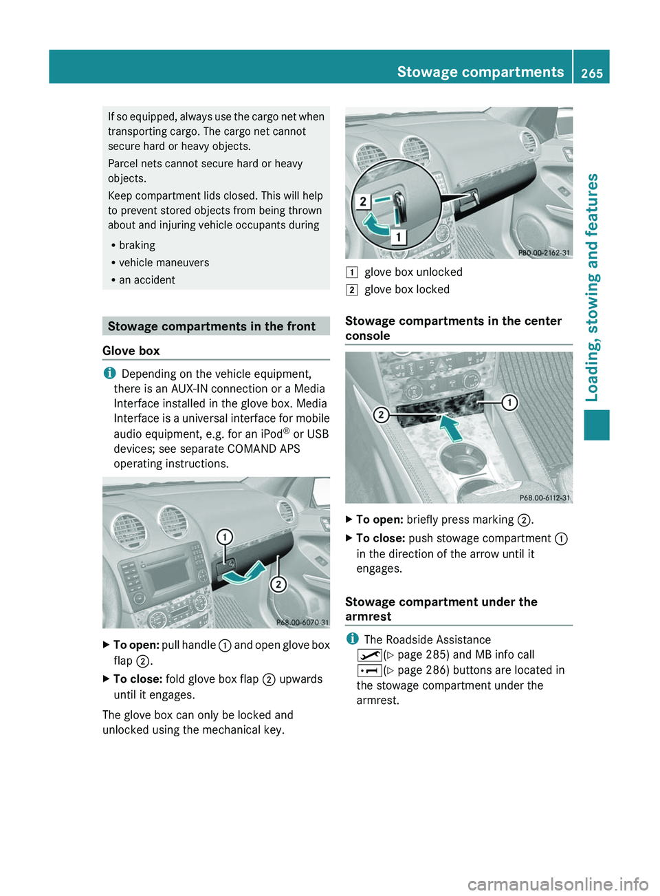
XTo open: pull handle : and open glove box
flap ;.XTo close: fold glove box flap ; upwards
until it engages.
The glove box can only be locked and
unlocked using the mechanical key.
1glove box unlocked2glove box locked
Stowage compartments in the center
console
XTo open: briefly press marking ;.XTo close: push stowage compartment :
in the direction of the arrow until it
engages.
Stowage compartment under the
armrest
i The Roadside Assistance
º (Y page 285) and MB info call
E (Y page 286) buttons are located in
the stowage compartment under the
armrest.
Stowage compartments265Loading, stowing and featuresBA 164.8 USA, CA Edition B 2011; 1; 2, en-USd2sboikeVersion: 3.0.3.52010-04-21T15:08:44+02:00 - Seite 265Z
Page 268 of 376
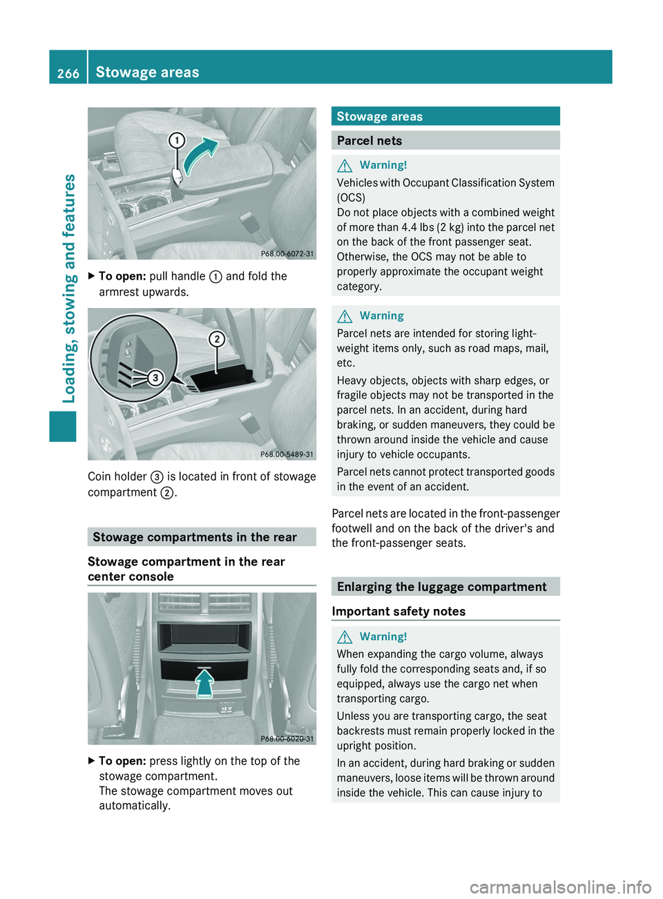
XTo open: pull handle : and fold the
armrest upwards.
Coin holder = is located in front of stowage
compartment ;.
Stowage compartments in the rear
Stowage compartment in the rear
center console
XTo open: press lightly on the top of the
stowage compartment.
The stowage compartment moves out
automatically.Stowage areas
Parcel nets
GWarning!
Vehicles with Occupant Classification System
(OCS)
Do not place objects with a combined weight
of more than 4.4 lbs (2 kg) into the parcel net
on the back of the front passenger seat.
Otherwise, the OCS may not be able to
properly approximate the occupant weight
category.
GWarning
Parcel nets are intended for storing light-
weight items only, such as road maps, mail,
etc.
Heavy objects, objects with sharp edges, or
fragile objects may not be transported in the
parcel nets. In an accident, during hard
braking, or sudden maneuvers, they could be
thrown around inside the vehicle and cause
injury to vehicle occupants.
Parcel nets cannot protect transported goods
in the event of an accident.
Parcel nets are located in the front-passenger
footwell and on the back of the driver's and
the front-passenger seats.
Enlarging the luggage compartment
Important safety notes
GWarning!
When expanding the cargo volume, always
fully fold the corresponding seats and, if so
equipped, always use the cargo net when
transporting cargo.
Unless you are transporting cargo, the seat
backrests must remain properly locked in the
upright position.
In an accident, during hard braking or sudden
maneuvers, loose items will be thrown around
inside the vehicle. This can cause injury to
266Stowage areasLoading, stowing and features
BA 164.8 USA, CA Edition B 2011; 1; 2, en-USd2sboikeVersion: 3.0.3.52010-04-21T15:08:44+02:00 - Seite 266
Page 274 of 376
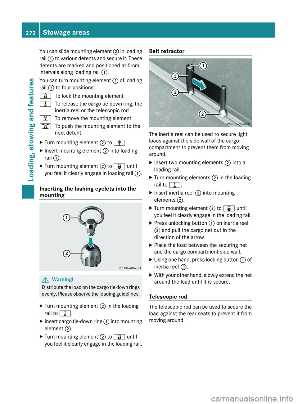
You can slide mounting element ; in loading
rail : to various detents and secure it. These
detents are marked and positioned at 5-cm
intervals along loading rail :.
You can turn mounting element ; of loading
rail : to four positions:&To lock the mounting element=To release the cargo tie-down ring, the
inertia reel or the telescopic rod;To remove the mounting elementBTo push the mounting element to the
next detentXTurn mounting element ; to ; .XInsert mounting element ; into loading
rail :.XTurn mounting element ; to & until
you feel it clearly engage in loading rail :.
Inserting the lashing eyelets into the
mounting
GWarning!
Distribute the load on the cargo tie down rings
evenly. Please observe the loading guidelines.
XTurn mounting element ; in the loading
rail to =.XInsert cargo tie-down ring : into mounting
element ;.XTurn mounting element ; to & until
you feel it clearly engage in the loading rail.Belt retractor
The inertia reel can be used to secure light
loads against the side wall of the cargo
compartment to prevent them from moving
around.
XInsert two mounting elements ; into a
loading rail.XTurn mounting elements ; in the loading
rail to =.XInsert inertia reel = into mounting
elements ;.XTurn mounting element ; to & until
you feel it clearly engage in the loading rail.XPress unlocking button : on inertia reel
= and pull the cargo net out in the
direction of the arrow.XPlace the load between the securing net
and the cargo compartment side wall.XUsing one hand, press locking button : of
inertia reel =.XWith your other hand, slowly extend the net
around the load until it is secure.
Telescopic rod
The telescopic rod can be used to secure the
load against the rear seats to prevent it from
moving around.
272Stowage areasLoading, stowing and features
BA 164.8 USA, CA Edition B 2011; 1; 2, en-USd2sboikeVersion: 3.0.3.52010-04-21T15:08:44+02:00 - Seite 272
Page 277 of 376
accessories and/or the objects attached to
them could come loose from the vehicle,
thereby injuring you and other persons and/
or causing damage to property, including
damage to your vehicle.
! Have a second person assist you when
installing the crossbars. Otherwise, the
vehicle could be damaged.
! Objects that are attached to crossbar
system accessories must not limit or
obstruct the movement of the sliding
sunroof. Otherwise, the tilt/sliding sunroof
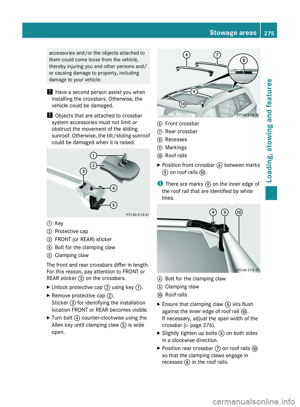
could be damaged when it is raised.:Key;Protective cap=FRONT (or REAR) sticker?Bolt for the clamping clawAClamping claw
The front and rear crossbars differ in length.
For this reason, pay attention to FRONT or
REAR sticker = on the crossbars.
XUnlock protective cap ; using key :.XRemove protective cap ;.
Sticker = for identifying the installation
location FRONT or REAR becomes visible.XTurn bolt ? counter-clockwise using the
Allen key until clamping claw A is wide
open.BFront crossbarCRear crossbarDRecessesEMarkingsFRoof railsXPosition front crossbar B between marks
E on roof rails F.
i
There are marks E on the inner edge of
the roof rail that are identified by white
lines.
?Bolt for the clamping clawAClamping clawFRoof railsXEnsure that clamping claw A sits flush
against the inner edge of roof rail F.
If necessary, adjust the span width of the
crossbar ( Y page 276).XSlightly tighten up bolts ? on both sides
in a clockwise direction.XPosition rear crossbar C on roof rails F
so that the clamping claws engage in
recesses D in the roof rails.Stowage areas275Loading, stowing and featuresBA 164.8 USA, CA Edition B 2011; 1; 2, en-USd2sboikeVersion: 3.0.3.52010-04-21T15:08:44+02:00 - Seite 275Z
Page 278 of 376
XEnsure that clamping claw A sits flush
against the inner edge of roof rail F.
If necessary, adjust the span width of the
crossbar ( Y page 276).XSlightly tighten up bolts ? on both sides
in a clockwise direction.XTighten up bolts ? on the front and rear
crossbars. Observe the tightening torque of
4 lb/ft (6 Nm) .GWarning!
Have the tightening torque checked after
mounting the crossbars. The screws could
come loose if they are not tightened to a
torque of 4 lb-ft (6 Nm).
XAttach and lock protective caps ;.XStow the key and Allen key in the stowage
compartment under the cargo
compartment floor again ( Y page 274).
Setting the span width of the crossbars
GWarning!
Only install the crossbars at the exact
locations designated on the roof rails. The
designated locations for the front crossbars
are between the markings engraved on the
inside of the roof rails. The designated
locations for the rear crossbars are between
the gaps on the roof rails.
Otherwise, the crossbars, mounted
accessories and the objects attached to them
could come loose from the vehicle causing an
accident, thereby injuring you and other
persons and/or causing damage to property,
including damage to your vehicle.
The span width of the crossbars for your
vehicle is set at the factory. The span widths
only fit in the intended positions on the
vehicle.
Only install the crossbars at the marked
positions and observe stickers = FRONT and
REAR.
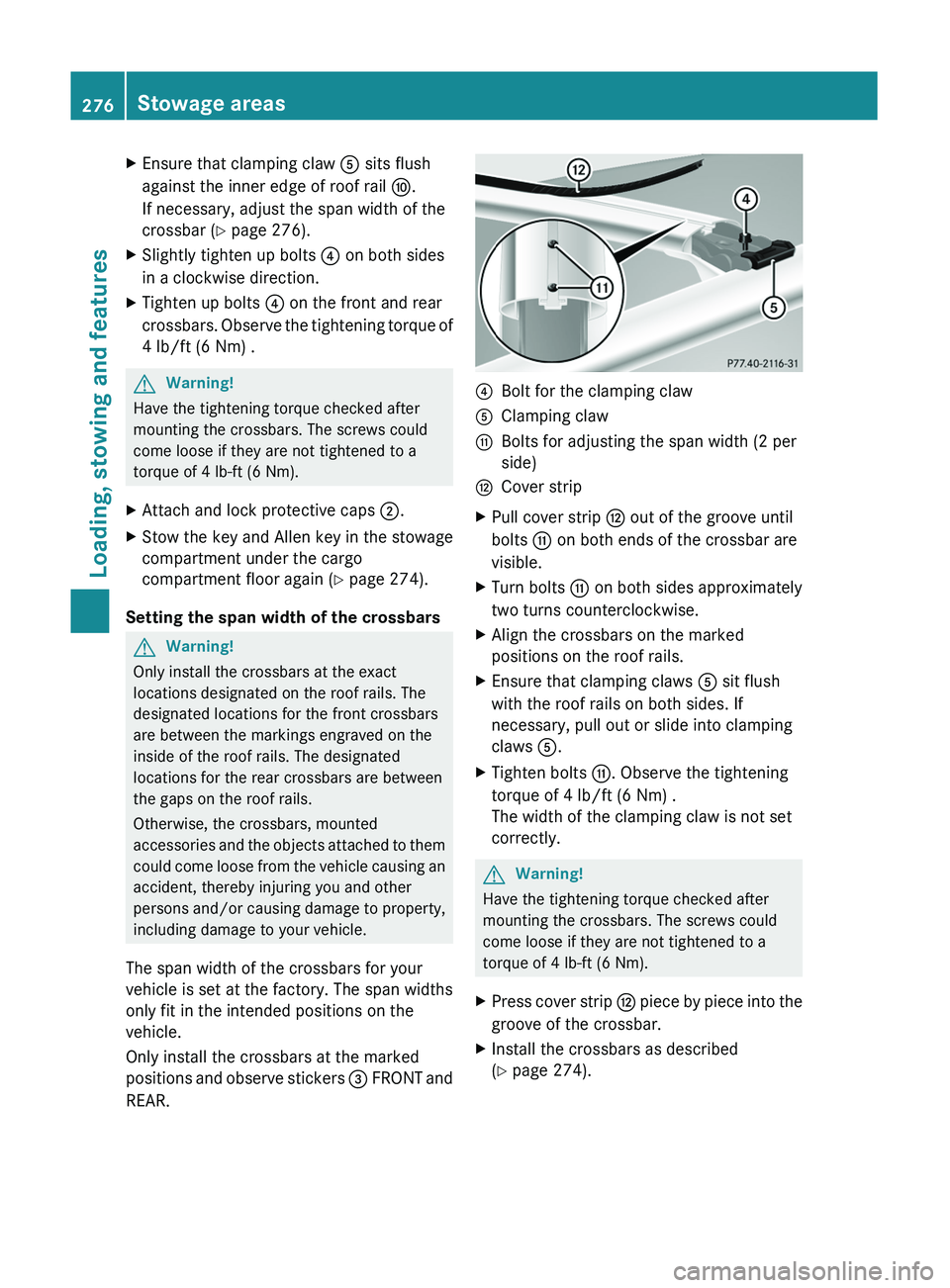
?Bolt for the clamping clawAClamping clawGBolts for adjusting the span width (2 per
side)HCover stripXPull cover strip H out of the groove until
bolts G on both ends of the crossbar are
visible.XTurn bolts G on both sides approximately
two turns counterclockwise.XAlign the crossbars on the marked
positions on the roof rails.XEnsure that clamping claws A sit flush
with the roof rails on both sides. If
necessary, pull out or slide into clamping
claws A.XTighten bolts G. Observe the tightening
torque of 4 lb/ft (6 Nm) .
The width of the clamping claw is not set
correctly.GWarning!
Have the tightening torque checked after
mounting the crossbars. The screws could
come loose if they are not tightened to a
torque of 4 lb-ft (6 Nm).
XPress cover strip H piece by piece into the
groove of the crossbar.XInstall the crossbars as described
( Y page 274).276Stowage areasLoading, stowing and features
BA 164.8 USA, CA Edition B 2011; 1; 2, en-USd2sboikeVersion: 3.0.3.52010-04-21T15:08:44+02:00 - Seite 276
Page 279 of 376
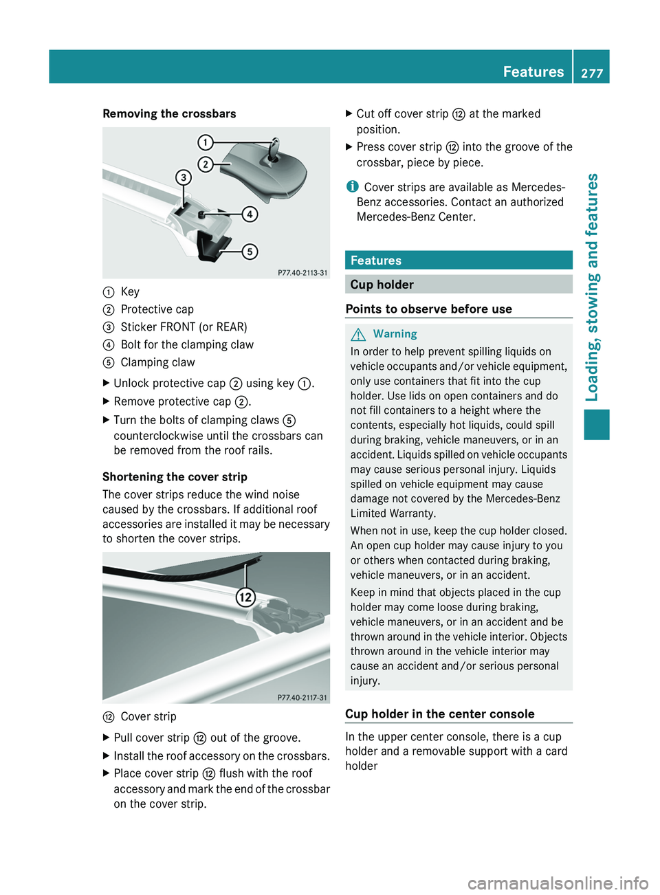
Removing the crossbars:Key;Protective cap=Sticker FRONT (or REAR)?Bolt for the clamping clawAClamping clawXUnlock protective cap ; using key :.XRemove protective cap ;.XTurn the bolts of clamping claws A
counterclockwise until the crossbars can
be removed from the roof rails.
Shortening the cover strip
The cover strips reduce the wind noise
caused by the crossbars. If additional roof
accessories are installed it may be necessary
to shorten the cover strips.
HCover stripXPull cover strip H out of the groove.XInstall the roof accessory on the crossbars.XPlace cover strip H flush with the roof
accessory and mark the end of the crossbar
on the cover strip.XCut off cover strip H at the marked
position.XPress cover strip H into the groove of the
crossbar, piece by piece.
i Cover strips are available as Mercedes-
Benz accessories. Contact an authorized
Mercedes-Benz Center.
Features
Cup holder
Points to observe before use
GWarning
In order to help prevent spilling liquids on
vehicle occupants and/or vehicle equipment,
only use containers that fit into the cup
holder. Use lids on open containers and do
not fill containers to a height where the
contents, especially hot liquids, could spill
during braking, vehicle maneuvers, or in an
accident. Liquids spilled on vehicle occupants
may cause serious personal injury. Liquids
spilled on vehicle equipment may cause
damage not covered by the Mercedes-Benz
Limited Warranty.
When not in use, keep the cup holder closed.
An open cup holder may cause injury to you
or others when contacted during braking,
vehicle maneuvers, or in an accident.
Keep in mind that objects placed in the cup
holder may come loose during braking,
vehicle maneuvers, or in an accident and be
thrown around in the vehicle interior. Objects
thrown around in the vehicle interior may
cause an accident and/or serious personal
injury.
Cup holder in the center console
In the upper center console, there is a cup
holder and a removable support with a card
holder
Features277Loading, stowing and featuresBA 164.8 USA, CA Edition B 2011; 1; 2, en-USd2sboikeVersion: 3.0.3.52010-04-21T15:08:44+02:00 - Seite 277Z
Page 282 of 376
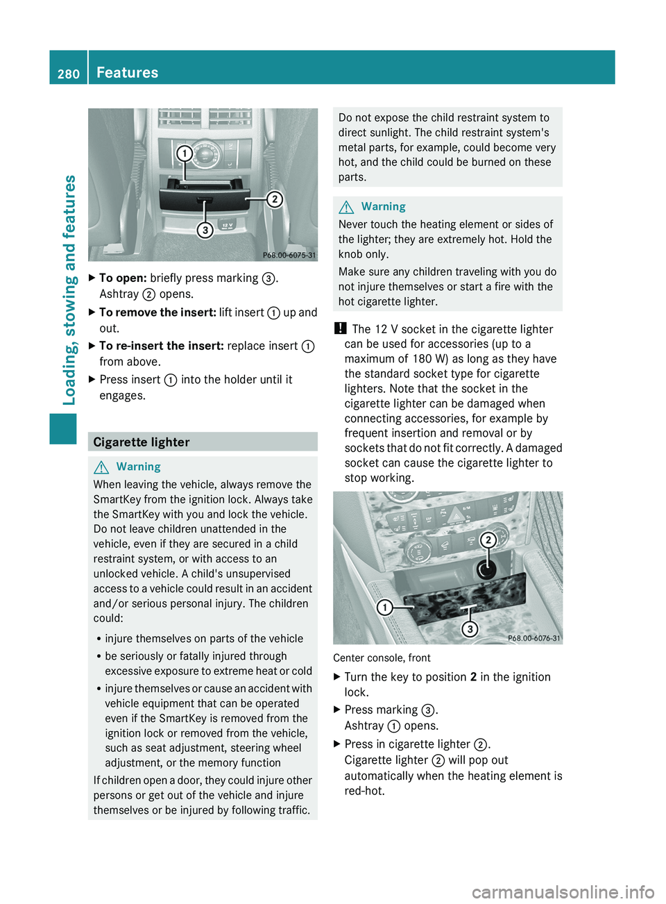
XTo open: briefly press marking =.
Ashtray ; opens.XTo remove the insert: lift insert : up and
out.XTo re-insert the insert: replace insert :
from above.XPress insert : into the holder until it
engages.
Cigarette lighter
GWarning
When leaving the vehicle, always remove the
SmartKey from the ignition lock. Always take
the SmartKey with you and lock the vehicle.
Do not leave children unattended in the
vehicle, even if they are secured in a child
restraint system, or with access to an
unlocked vehicle. A child's unsupervised
access to a vehicle could result in an accident
and/or serious personal injury. The children
could:
R injure themselves on parts of the vehicle
R be seriously or fatally injured through
excessive exposure to extreme heat or cold
R injure themselves or cause an accident with
vehicle equipment that can be operated
even if the SmartKey is removed from the
ignition lock or removed from the vehicle,
such as seat adjustment, steering wheel
adjustment, or the memory function
If children open a door, they could injure other
persons or get out of the vehicle and injure
themselves or be injured by following traffic.
Do not expose the child restraint system to
direct sunlight. The child restraint system's
metal parts, for example, could become very
hot, and the child could be burned on these
parts.GWarning
Never touch the heating element or sides of
the lighter; they are extremely hot. Hold the
knob only.
Make sure any children traveling with you do
not injure themselves or start a fire with the
hot cigarette lighter.
! The 12 V socket in the cigarette lighter
can be used for accessories (up to a
maximum of 180 W) as long as they have
the standard socket type for cigarette
lighters. Note that the socket in the
cigarette lighter can be damaged when
connecting accessories, for example by
frequent insertion and removal or by
sockets that do not fit correctly. A damaged
socket can cause the cigarette lighter to
stop working.
Center console, front
XTurn the key to position 2 in the ignition
lock.XPress marking =.
Ashtray : opens.XPress in cigarette lighter ;.
Cigarette lighter ; will pop out
automatically when the heating element is
red-hot.280FeaturesLoading, stowing and features
BA 164.8 USA, CA Edition B 2011; 1; 2, en-USd2sboikeVersion: 3.0.3.52010-04-21T15:08:44+02:00 - Seite 280