Page 302 of 353

TIREFI
Tkit version 2 X
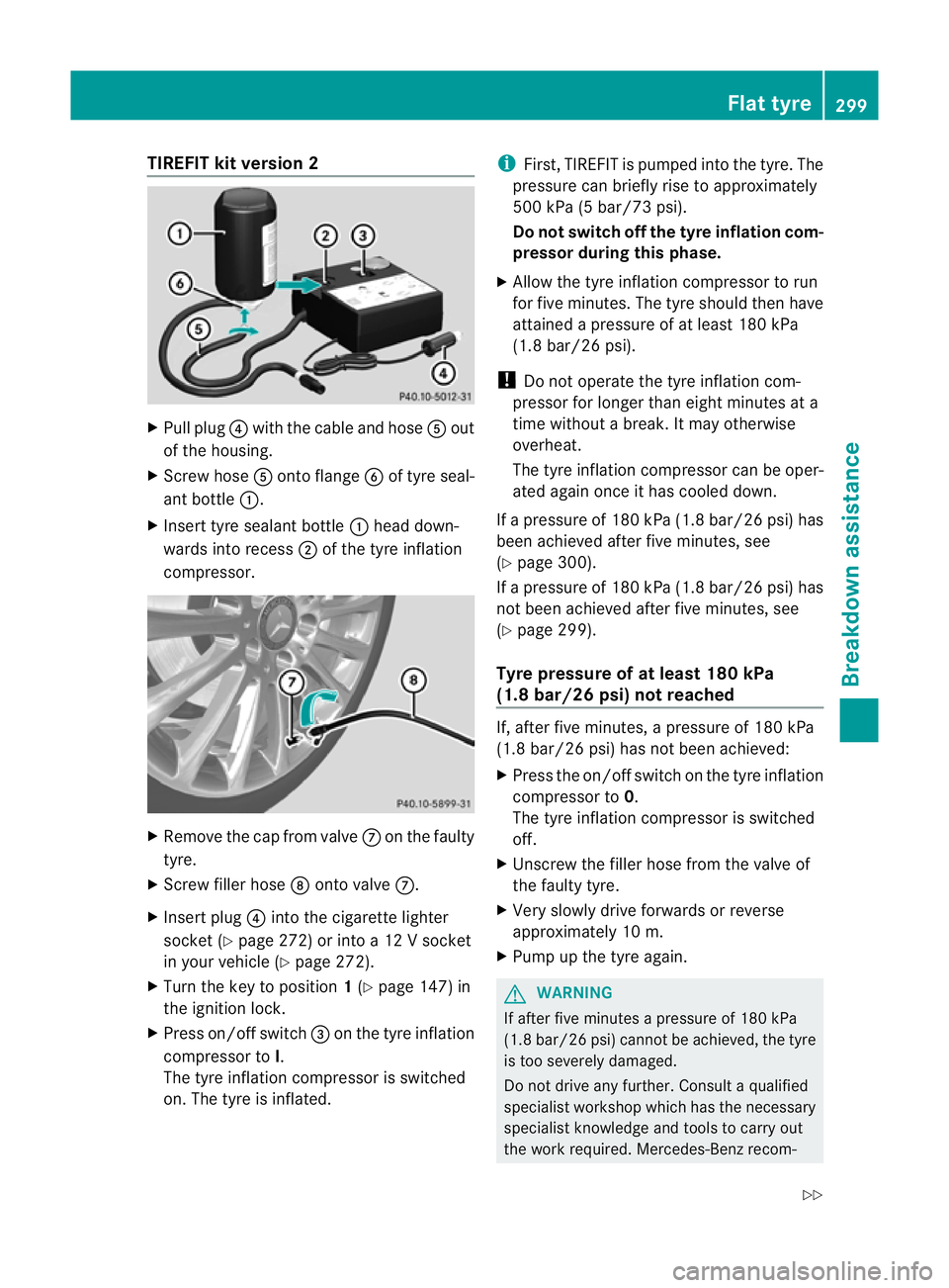
Pull plug ?with the cable and hose Aout
of the housing.
X Screw hose Aontoflange Bof tyre seal-
ant bottle :.
X Insert tyre sealant bottle :head down-
wards int orecess ;of the tyre inflation
compressor. X
Remove the cap from valve Con the faulty
tyre.
X Screw filler hose Dontovalve C.
X Insert plug ?intot he cigarett elighter
socket (Y page 272)orintoa12Vs ocket
in your vehicle (Y page 272).
X Turn the key to position 1(Y page 147 )in
the ignition lock.
X Press on/off switch =on the tyre inflation
compressor to I.
The tyre inflation compressor is switched
on. The tyre is inflated. i
First, TIREFIT is pumped int othe tyre. The
pressure can briefly rise to approximately
500 kPa (5 bar/7 3psi).
Do not switch off the tyrei nflation com-
pressor during this phase.
X Allow the tyre inflation compressor to run
for five minutes. The tyre should then have
attained apressure of at least 180 kPa
(1.8 bar/26 psi).
! Do not operate the tyre inflation com-
pressor for longer than eight minutes at a
time without abreak. It may otherwise
overheat.
The tyre inflation compressor can be oper-
ated again once it has cooled down.
If ap ressure of 180 kPa (1.8 bar/26 psi) has
been achieved after five minutes, see
(Y page 300).
If ap ressure of 180 kPa (1.8 bar/26 psi) has
not been achieved after five minutes, see
(Y page 299).
Tyrep ressur eofatleast 180 kPa
(1.8 bar/26 psi) not reached If, after five minutes,
apressure of 180 kPa
(1.8 bar/26 psi) has not been achieved:
X Press the on/off switch on the tyre inflation
compressor to 0.
The tyre inflation compressor is switched
off.
X Unscrew the filler hose from the valve of
the faulty tyre.
X Very slowly drive forwards or reverse
approximately 10 m.
X Pump up the tyre again. G
WARNING
If after five minutes apressure of 180 kPa
(1.8 bar/26 psi) cannot be achieved, the tyre
is too severel ydamaged.
Do not drive any further. Consult aqualified
specialist workshop which has the necessary
specialist knowledge and tools to carry out
the work required. Mercedes-Benz recom- Flat tyre
299Breakdown assistance
Z
Page 305 of 353

X
Fold both plates upwards :.
X Fold ou tlower plate ;.
X Guide the lugs on the lower plate fully into
the openings in base plate =.Securing the vehicle on level ground (example:
Coupé)
X
On level ground: place chocksorother
suitable items under the front and rear of
the wheel that is diagonally opposite the
wheel you wish to change. Securing the vehicle on slight downhill gradients
(example: Coupé)
X On downhill gradients: place chocksor
other suitable items in front of the wheels
of the front and rear axle.
Raising the vehicle G
WARNING
The jack is intended only for lifting the vehicle
briefly for wheel changes.
The vehicle must be placed on stands if you
intendtow ork under it. Make sure that the jack is placed on
afirm,
non-slip, level surface. Do not use wooden
blocks or similar object sasajack underlay.
The vehicle could otherwise slip off the jack
and seriously injure you.
Do not start the engine at any time while the
wheel is being changed.
Do not lie under the vehicle when it is being
supported by the jack.Ify ou do not raise the
vehicle as described, it could slip off the jack
(e.g. if the engine is started or adoor or the
boot lid is opened or closed) and seriously
injure you. G
WARNING
If you fail to position the jack correctly, the
vehicle may:
R slip off the jack
R injure you or others
R be damaged.
Therefore, make sure that the jack is posi-
tioned correctly in the respectiv ejacking
points. Before positioning the jack,r emove
any dirt that may have collected in the jacking
points. Please note that you must position the
jack in the opening of the jacking point. X
Using wheel wrench :,loosen the bolts on
the wheel you wish to change by about one
full turn. Do not unscrew the bolts com-
pletely.
The jacking points for the jack are located
behind the wheel housings of the front wheels
and in front of the wheel housings of the rear
wheels (arrows). 302
Flat tyreBreakdown assistance
Page 317 of 353

Blow
nfuses must be replace dwith fuses of
the same rating, which you can recognise by
the colour and value. The fuse ratings are lis-
ted in the fuse allocation chart. AMercedes-
BenzS ervice Centr ewill be happy to advise
you.
If the newly inserted fuse also blows, have the
cause traced and rectified at aqualified spe-
cialist workshop, e.g. aMercedes-Benz
Service Centre.
! Only use fuses that have been approved
for Mercedes-Benz vehicles and which
have the correct fuse ratin gfor the system
concerned. Otherwise, componentsors ys-
tems could be damaged. Befor
echanging afuse
X Park the vehicle and apply the parking
brake.
X Switc hoff all electrical consumers.
X Remove the key from the ignition lock.
The fuses are located in various fuse boxes:
R fuse box on the driver's side of the dash-
board
R fuse box in the engin ecompartment on the
left-hand side of the vehicle, when viewed
in the direction of travel
R fuse box in the boot on the right-hand side
of the vehicle, when viewed in the direction
of travel
The fuse allocation chart is located in the
vehicle tool kit (Y page 295)inthe stowage
compartment under the boot floor. Dashboar
dfuse box
! Do not use apointed objec tsuch as a
screwdriver to open th ecover in th edash-
board. You could damag ethe dashboard or
the cover. X
To open: pull out cover :slightly at the
botto mint hedirection of arrow =.
X Pull cover :outwards in th edirection of
arrow ;and remove it.
X To close: clip in cover :on th efront of
th ed ashboard.
X Fol dc over : inwards until it engages. Fuse box in th
eengine compartment
X Mak esure that th ewindscree nwipers are
turned off. G
WARNING
Make sure that the windscreen wipers are
turned off and the key is pulled out of the igni-
tion lock befor eyou open the cover of the fuse
box. Otherwise, the windscreen wipers and
the wiper rods above the cover could be set
in motion. This could lead to you or others
being injured by the wiper rods.
X Open the bonnet (Y page 281).314
Electrical fusesBreakdown assistance
Page 330 of 353

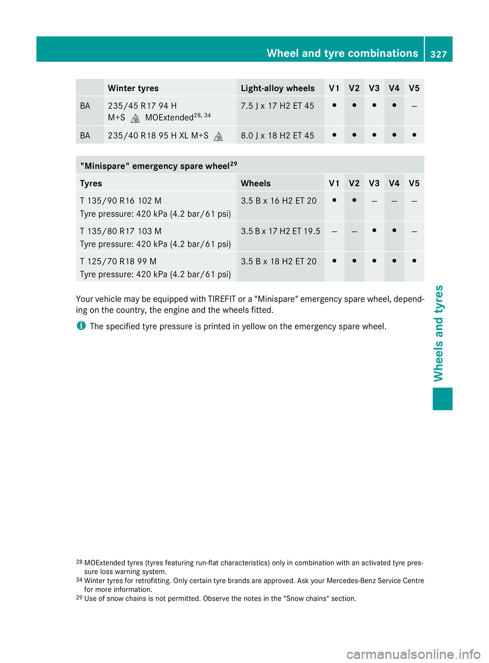
Winter tyres Light-alloy wheels V1 V2 V3 V4 V5
BA 235/45 R17 94 H
M+SiMOExtended
28, 34 7.5
Jx17H2ET45 # # # #
—
BA 235/40 R18 95
HXLM+Si 8.0
Jx18H2ET45 # # # # #
"Minispare" emergency spare wheel
29Tyres Wheels V1 V2 V3 V4 V5
T1
35/90 R16 102 M
Tyre pressure: 420 kPa (4.2 bar/61 psi) 3.5
Bx16H2ET20 # #
— — —
T1
35/80 R17 103 M
Tyre pressure: 420 kPa (4.2 bar/61 psi) 3.5
Bx17H2ET1 9.5 — — # #
—
T1
25/70 R18 99 M
Tyre pressure: 420 kPa (4.2 bar/61 psi) 3.5
Bx18H2ET20 # # # # #
Yourv
ehicle may be equipped with TIREFIT or a"Minispare" emergency spare wheel, depend-
ing on the country, the engin eand the wheels fitted.
i The specified tyre pressure is printed in yellow on the emergency spare wheel.
28 MOExtended tyres (tyres featurin grun-flat characteristics) only in combination with an activated tyre pres-
sure loss warning system.
34 Winter tyres for retrofitting. Only certain tyre brands are approved. Ask your Mercedes-Ben zService Centre
for more information.
29 Use of snow chains is not permitted. Observe the notes in the "Snow chains" section. Wheel and tyrec
ombinations
327Wheels and tyres Z