2011 MERCEDES-BENZ C-CLASS COUPE flat tire
[x] Cancel search: flat tirePage 15 of 373
F
Fatigue Assist see ATTENTION ASSIST
Fault message
see Display messages
Filler cap
see Fuel fille rflap
Fire extinguisher ............................... 315
First-aid kit ......................................... 314
Flat tyre Changing a wheel/fitting the
spare wheel ................................... 321
MOExtended run-fla tsystem ......... 324
Preparing the vehicle .....................316
Raising the vehicle .........................322
TIREFIT kit ...................................... 317
Floormat ............................................ .297
Foglamps Extended range .............................. 112
Switching on/off ........................... 109
Frequencies
Garage door opene r....................... 297
Mobile phone ................................. 351
Two-way radio ................................ 351
Fron tfoglamp
Display message (12-butto nmul-
tifunction steering wheel) ..............249
Front foglamps
Display message (4-button multi-
function steering wheel) ................246
Switching on/off ........................... 109
Fron twindscreen
see Windscreen
Fuel
Displaying the range (12-button
multifunction steering wheel) ........215
Displaying the range (4-button
multifunctio nsteering wheel) ........210
Important safety notes ..................354
Notes about consumption .............354
Problem (malfunction) ...................157
Refuelling ...................................... .152
Tank content/reserve fuel .............354
Tank content display (12-button
multifunctio nsteering wheel) ..........35
Tank content display (4-button
multifunctio nsteering wheel) ..........32Fuel consumption
Current (12-button multifunction
steering wheel) .............................. 215
Fuel filler flap
Opening/closing ............................ 155
Fuel filter
Display message (12-button mul-
tifunctio nsteering wheel) ..............255
Display message (4-button multi-
function steering wheel) ................253
Fuel reserve
Display message (12-button mul-
tifunctio nsteering wheel) ..............255
Display message (4-button multi-
function steering wheel) ................253
see Fuel
Fuel tank
Capacity ........................................ 354
Problem (malfunction) ...................157
Fuse allocation chart (vehicle tool
kit) ...................................................... 315
Fuses Allocation chart ............................. 334
Before changing ............................. 334
Fuse box in the boot ......................334
Fuse box in the engine compart-
ment .............................................. 334
Important safety notes ..................333 G
Garage door opener Clearing the memory .....................296
Frequencies ................................... 297
Notes ............................................. 294
Opening/closing the garage door ..295
Programming (button in the rear-
view mirror) ................................... 294
Gear indicator (12-button multi-
function steering wheel) ..................229
Gearshift program SETUP (on-board computer) ..........229
Genuine Mercedes-Benz parts .........350
Glove compartment ..........................28512
Index
Page 25 of 373

Couplin
gupatrailer...................... 202
Decoupling atrailer ....................... 202
Driving tips .................................... 199
ESP ®
................................................ 70
Folding in the ball coupling ............202
Folding out the ball coupling ..........201
Important safety notes ..................199
Mounting dimensions ....................361
Parking Guidance ........................... 186
Parktroni c...................................... 182
Power supply ................................. 203
Shift range ..................................... 147
Trailer loads ................................... 362
Transmission
see Automatic transmission
see Manual transmission
Transporting the vehicle ..................332
Trim pieces (cleaning instructions) .311
Trip computer On-board computer (12-button
multifunctio nsteering wheel) ........215
On-board computer (4-button
multifunctio nsteering wheel) ........210
Trip meter
Displaying/resetting (4-button
multifunctio nsteering wheel) ........209
Displaying (12-button multifunc-
tion steering wheel) .......................215
Resetting (12-button multifunc-
tion steering wheel) .......................216
Trip odometer
see Trip meter
Turn signal
Display message (12-button mul-
tifunctio nsteering wheel) ..............248
Display message (4-button multi-
function steering wheel) ................245
Turn signals
Switching on/off ........................... 110
Two-way radio
Frequencies ................................... 351
Installatio n..................................... 351
Transmission output (maximum) .... 351
Type identification plate
see Vehicle identification plate Tyre pressure
Calling up (on-board computer) .....342
Display message (12-button mul-
tifunctio nsteering wheel) ..............263
Display message (4-button multi-
function steering wheel) ................262
Not reached (TIREFIT) ....................319
Pressure loss warning ....................340
Reached (TIREFIT) ..........................320
Recommended ............................... 339
Tyre pressure monitor
Function/notes ............................. 342
Restarting ...................................... 343
Warning lamp ................................. 282
Tyres
Checking ........................................ 336
Direction of rotatio n...................... 344
Display message (12-button mul-
tifunctio nsteering wheel) ..............263
Display message (4-button multi-
function steering wheel) ................262
Grip ................................................ 161
Important safety notes ..................336
Replacing ....................................... 344
Service life ..................................... 337
Storing ........................................... 344
Tyr esize (data) .............................. 345
Tyr etread ...................................... 337
see Flat tyre U
Unladen weight see Technical data
Unlocking
Emergency unlocking .......................85
From inside the vehicle (central
unlocking button) ............................. 84 V
Vanity mirror (in sun visor) ..............290
Vehicle Correct use ...................................... 27
Data acquisition ............................... 27
Electronics ..................................... 351
Equipment ....................................... 25
Implied warranty .............................. 27
Individua lsettings .......................... 22322
Index
Page 318 of 373
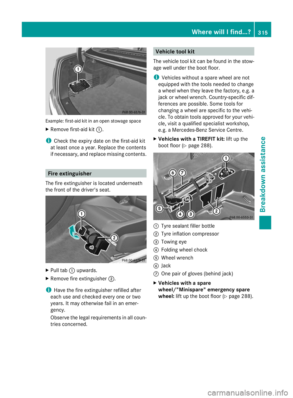
Example: first-aid kit in an open stowage space
X Remove first-aid kit :.
i Check the expiry date on the first-aid kit
at leas tonce a year .Replace the contents
if necessary, and replace missing contents. Fire extinguisher
The fire extinguisher is located underneath
the front of the driver's seat. X
Pull tab :upwards.
X Remove fire extinguisher ;.
i Have the fire extinguisher refilled after
each use and checked every one or two
years. It may otherwise fail in an emer-
gency.
Observe the legal requirement sinall coun-
tries concerned. Vehicle tool kit
The vehicle tool kit can be found in the stow-
age well under the boot floor.
i Vehicles without a spare wheel are not
equipped with the tools needed to change
a wheel when they leave the factory, e.g. a
jac korw heel wrench. Country-specific dif-
ferences are possible. Some tools for
changing a wheel are specific to the vehi-
cle. To obtain tools approved for your vehi-
cle, visit a qualified specialist workshop,
e.g. a Mercedes-Benz Service Centre.
X Vehicles with a TIREFIT kit: lift up the
boot floor (Y page 288). :
Tyre sealant filler bottle
; Tyre inflation compressor
= Towing eye
? Folding wheel chock
A Wheel wrench
B Jack
C One pair of gloves (behind jack)
X Vehicles with a spare
wheel/"Minispare" emergency spare
wheel: lift up the boot floor (Y page 288). Where will I find...?
315Breakdown assistance
Page 319 of 373

:
Vehicle tool kit tray
; Stowage well
= Spare wheel/"Minispare" emergency
spare wheel
The vehicle tool kit contains:
R Foldable wheel chock
R Fuse allocation chart
R Jack
R One pair of gloves
R Wheel wrench
R Towing eye Spare wheel/"Minispare" emergency
spare wheel
The spare wheel or "Minispare" emergency
spare wheel can be found in the stowage well
under the boot floor.
X Lift the boot floor upwards (Y page 288). X
To remove the spare wheel or
"Minispare" emergencys pare wheel:
remove vehicle tool kit tray :.
X Turn stowage well ;anti-clockwise and
remove it.
X Remove the spare wheel or "Minispare"
emergency spare wheel =.
For further information on changing a wheel
and fitting the spare wheel, see
(Y page 321). Flat tyre
Preparing the vehicle
Your vehicle may be equipped with:
R a TIREFIT kit
R an emergency spare wheel
R MOExtended tyres (tyres with run-flat char-
acteristics) (Y page 324)
i Vehicle preparation is not necessary on
vehicles with MOExtended tyres.
i Vehicles with MOExtended tyres are not
equipped with a TIREFIT kit at the factory.
It is therefore recommended that you addi-
tionally equip your vehicle with a TIREFIT kit
if you fit tyres that do not feature run-flat
properties, e.g. winter tyres. A TIREFIT kit
can be obtained from a Mercedes-Benz
Service Centre.
X Stop the vehicle as far away as possible
from traffic on solid ,non-slippery and level
ground.
X Switch on the hazard warning lamps.
X Firmly depress the parking brake.
X Bring the front wheels into the straight-
ahead position.
X Vehicles with manual transmission:
engage first or reverse gear.
X Vehicles with automatic transmission:
move the selector lever to P.
X Switch off the engine. 316
Flat tyreBreakdown assistance
Page 320 of 373

X
Vehicles withou tKEYLESS-GO: remove
the key from the ignition lock.
X Vehicles with KEYLESS-GO: open the
driver's door.
The on-board electronics have status 0,
which is the same as the key having been
removed.
X Vehicles with KEYLESS-GO: remove the
Start/Stop button from the ignition lock
(Y page 137).
X All occupants must get out of the vehicle.
Make sure that they are no tendangered as
they do so.
X Make sure tha tno one is near the danger
area whilst a wheel is being changed. Any-
one who is not directly assisting in the
wheel change should, for example, stand
behind the barrier.
X Get out of the vehicle. Pay attention to traf-
fic conditions when doing so.
X Close the driver's door.
X Place the warning triangle (Y page 314) a
suitable distance away.O bserve legal
requirements. TIREFIT kit
Using the TIREFIT kit You can use the TIREFIT kit to seal small
punctures, particularly those in the tyre tread.
You can use TIREFIT at outside temperatures
down to -20 †. G
WARNING
In the following situations, your safety is at
particular risk as tyre sealant is unable to pro-
vide sufficient breakdown assistance:
R there are cuts or punctures in the tyre
greater than 4 mm.
R the wheel rim is damaged.
R you have driven at very low tyre pressures
or on a flat tyre.
Do not drive any further. Consult a qualified
specialist workshop which has the necessary specialist knowledge and tools to carry out
the work required.
Mercedes-Benz recommends that you use a
Mercedes-Benz Service Centre for this pur-
pose. In particular, work relevant to safety or
on safety-related system
smust be carried out
at a qualified specialist workshop.
X Do not remove any foreign objects which
have penetrated the tyre, e.g .screws or
nails.
X Remove the tyre sealant bottle, the accom-
panying "max. 80 km/h" sticker and the
tyre inflation compressor from the stowage
well underneath the boo tfloor
(Y page 315). X
Affix part :of the sticker within the driv-
er's field of vision.
X Affix part ;of the sticker near the valve
on the wheel with the defective tyre. G
WARNING
TIREFIT must not com einto contact with your
skin, eyes or clothing.
R If TIREFIT comes into contact with your
eyes or skin, immediately rinse thoroughly
with clean water.
R Change ou tofclothing which has come into
contact with TIREFIT immediately.
R If an allergic reaction occurs, consult a doc-
tor immediately.
Keep TIREFIT away fro mchildren. Flat tyre
317Breakdown assistance
Z
Page 321 of 373
R
If TIREFIT is swallowed, immediately rinse
yourm outh out thoroughly and drink plenty
of water.
R Do not induce vomiting. Consult a doctor
immediately.
R Do not inhale TIREFIT fumes.
i If TIREFIT leaks out, allow it to dry. It can
then be removed like a layer of film.
If you get TIREFIT on your clothing, have it
cleaned as soon as possible with perchloro-
ethylene.
Your vehicle is provided with one of two dif-
ferent TIREFIT kits:
R Version 1: the tyre inflation compressor
and the tyre filler bottle both have their own
fixed hoses.
R Version 2: the tyre inflation compressor
and the tyre filler bottle do not come with
a fixed hose. This is in the housing of the
tyre inflation compressor.
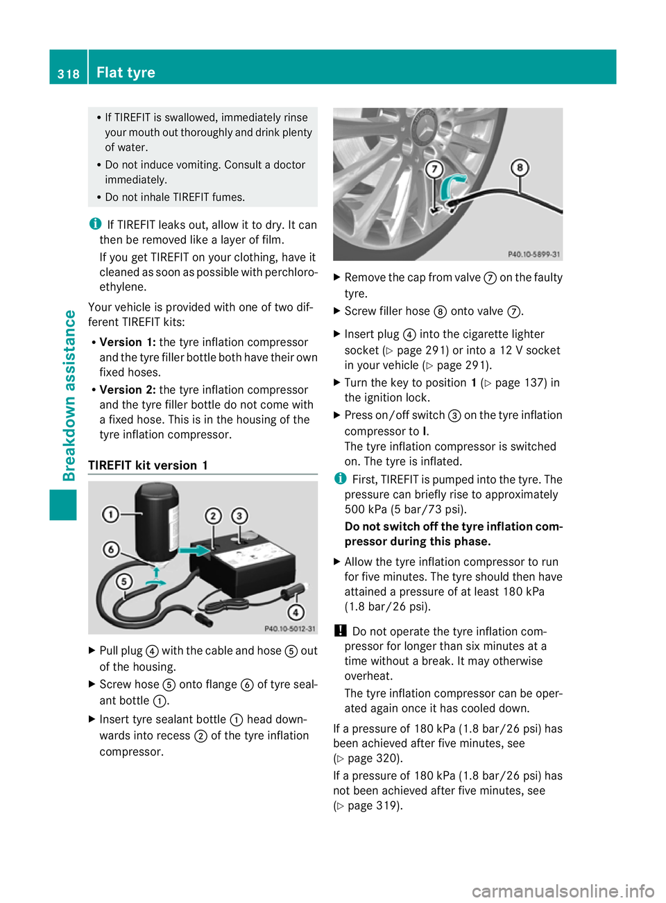
TIREFIT kit version 1 X
Pull plug ?with the cable and hose Aout
of the housing.
X Screw hose Aonto flange Bof tyre seal-
ant bottle :.
X Insert tyre sealant bottle :head down-
wards into recess ;of the tyre inflation
compressor. X
Remove the cap from valve Con the faulty
tyre.
X Screw filler hose Donto valve C.
X Insert plug ?into the cigarette lighter
socket (Y page 291) or into a 12 V socket
in your vehicle (Y page 291).
X Turn the key to position 1(Y page 137) in
the ignition lock.
X Press on/offs witch=on the tyre inflation
compressor to I.
The tyre inflatio ncompressor is switched
on. The tyre is inflated.
i First, TIREFIT is pumped into the tyre. The
pressure can briefly rise to approximately
500 kPa (5 bar/73 psi).
Do not switch off the tyre inflation com-
pressor during this phase.
X Allow the tyre inflation compressor to run
for five minutes. The tyre should then have
attained a pressure of at least 180 kPa
(1.8 bar/26 psi).
! Do not operate the tyre inflation com-
pressor for longer than six minutes at a
time without a break. It may otherwise
overheat.
The tyre inflation compressor can be oper-
ated again once it has cooled down.
If a pressure of 180 kPa (1.8 bar/26 psi) has
been achieved after five minutes, see
(Y page 320).
If a pressure of 180 kPa (1.8 bar/26 psi) has
not been achieved after five minutes, see
(Y page 319). 318
Flat tyreBreakdown assistance
Page 322 of 373
TIREFI
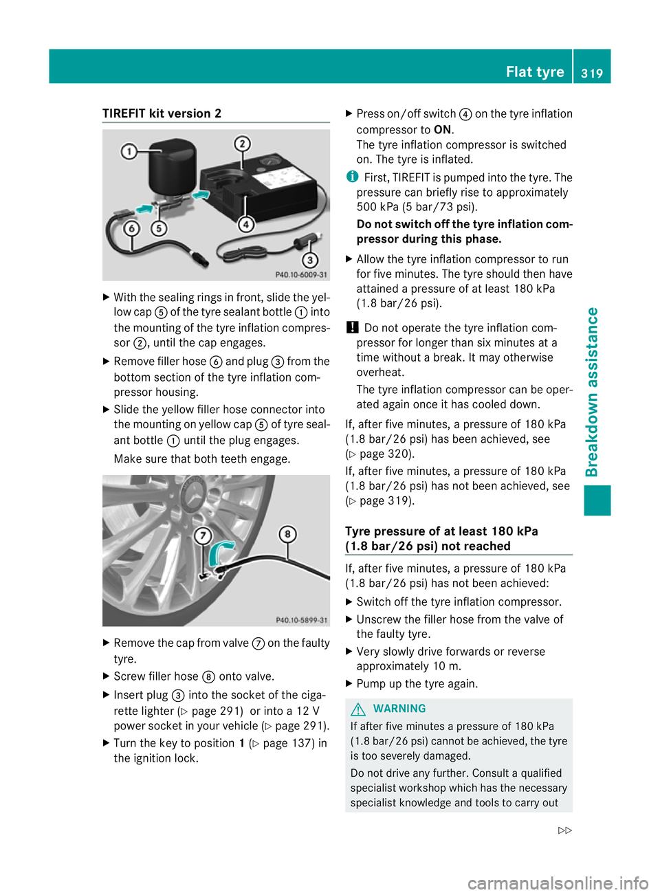
Tkit version 2 X
With the sealing rings in front, slide the yel-
low cap Aof the tyre sealant bottle :into
the mounting of the tyre inflation compres-
sor ;, until the cap engages.
X Remove filler hose Band plug =from the
bottom section of the tyre inflation com-
pressor housing.
X Slide the yellow filler hose connector into
the mounting on yellow cap Aof tyre seal-
ant bottle :until the plug engages.
Make sure that both teeth engage. X
Remove the cap from valve Con the faulty
tyre.
X Screw filler hose Donto valve.
X Insert plug =into the socket of the ciga-
rette lighter (Y page 291) or into a 12 V
power socket in your vehicle (Y page 291).
X Turn the key to position 1(Y page 137) in
the ignition lock. X
Press on/off switch ?on the tyre inflation
compressor to ON.
The tyre inflation compressor is switched
on. The tyre is inflated.
i First, TIREFIT is pumped into the tyre .The
pressure can briefly rise to approximately
500 kPa (5 bar/73 psi).
Do not switch off the tyre inflation com-
pressor during this phase.
X Allow the tyre inflation compressor to run
for five minutes. The tyre should then have
attained a pressure of at least 180 kPa
(1.8 bar/26 psi).
! Do not operate the tyre inflation com-
pressor for longer than six minutes at a
time without a break. It may otherwise
overheat.
The tyre inflation compressor can be oper-
ated again once it has cooled down.
If, after five minutes, a pressure of 180 kPa
(1.8 bar/26 psi) has been achieved, see
(Y page 320).
If, after five minutes, a pressure of 180 kPa
(1.8 bar/26 psi) has not been achieved, see
(Y page 319).
Tyre pressure of at least 180 kPa
(1.8 bar/26 psi) not reached If, after five minutes, a pressure of 180 kPa
(1.8 bar/26 psi) has not been achieved:
X
Switch off the tyre inflation compressor.
X Unscrew the filler hose from the valve of
the faulty tyre.
X Very slowly drive forwards or reverse
approximately 10 m.
X Pump up the tyre again. G
WARNING
If after five minutes apressure of 180 kPa
(1.8 bar/26 psi) cannot be achieved, the tyre
is too severely damaged.
Do not drive any further. Consult a qualified
specialist workshop which has the necessary
specialist knowledge and tools to carry out Flat tyre
319Breakdown assistance
Z
Page 323 of 373
the work required. Mercedes-Benz recom-
mends tha tyou use a Mercedes-Benz Service
Centre for this purpose. In particular, work
relevant to safety or on safety-related sys-
tems must be carried out at a qualified spe-
cialist workshop.
Tyre pressure of 180 kPa (1.8 bar/
26 psi) is reached X
Switch off the tyre inflation compressor.
X Unscrew the filler hose from the valve of
the faulty tyre.
! After use, excess TIREFIT may run out of
the filler hose. This may cause stains.
Therefore, place the filler hose in the plastic
bag which contained the TIREFIT kit.
X Stow the tyre sealant bottle, the tyre infla-
tion compressor and the warning triangle.
X Pull away immediately. G
WARNING
Do not exceed the maximum speed of
80 km/h.
The "max. 80 km/h" label must be affixed in
the driver's field of vision.
The vehicle's handling characteristics may be
affected.
X Stop after driving for approximately ten
minutes and check the tyre pressure with
the tyre inflation compressor. G
WARNING
If the tyre pressure is less than 130 kPa
(1.3 bar/20 psi), the tyre is too severely dam-
aged. Do not drive any further. Consult a
qualified specialist workshop which has the
necessary specialist knowledge and tools to
carry out the work required. Mercedes-Benz
recommends that you use aMercedes-Benz
Service Centre for this purpose. In particular,
work relevant to safety or on safety-related
systems must be carried out at a qualified
specialist workshop. X
Correct the tyre pressure if it is still at least
130 kPa (1.3 bar/20 psi) (for the values,
see the fuel filler flap).
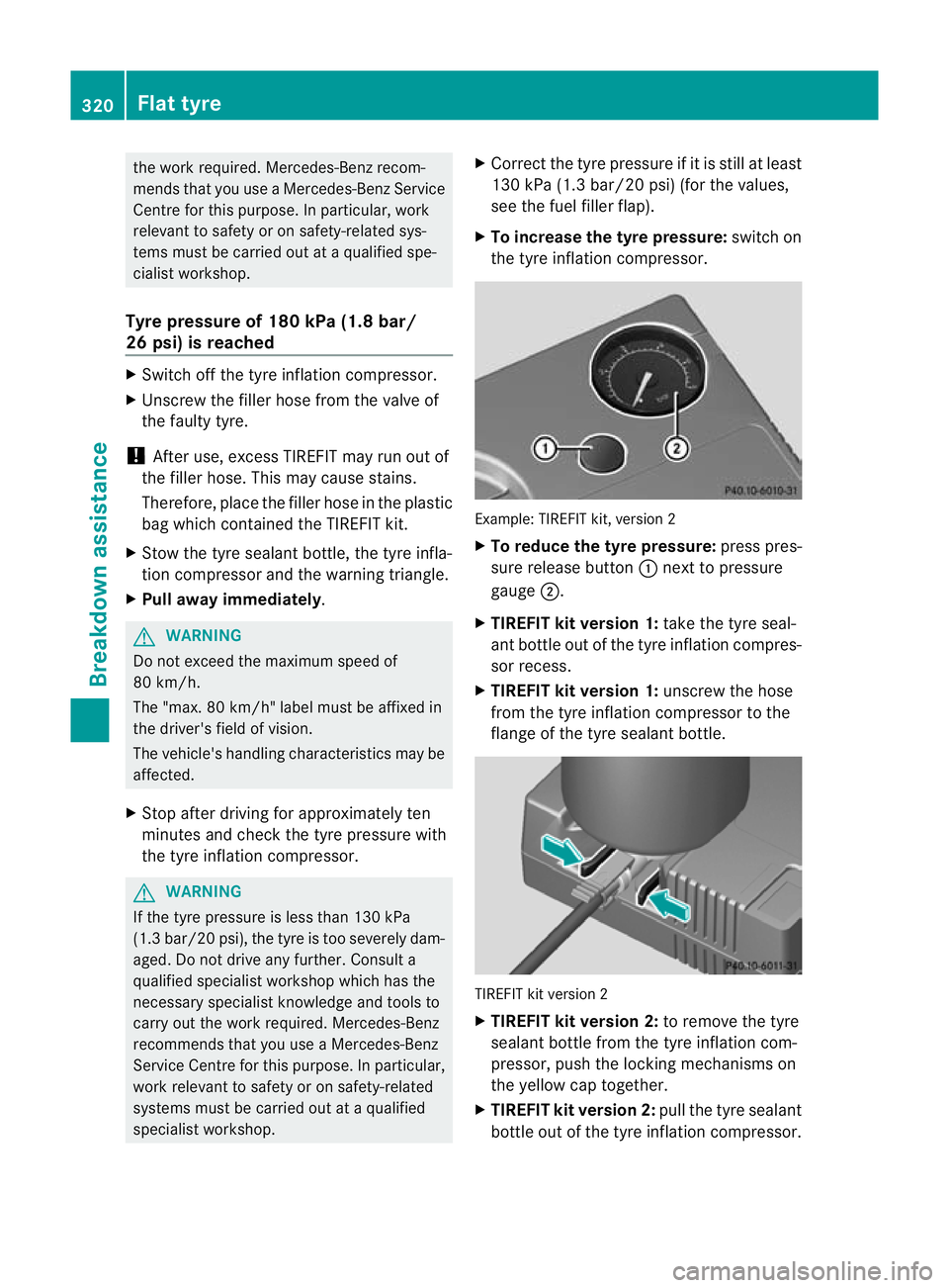
X To increase the tyre pressure: switch on
the tyre inflation compressor. Example: TIREFIT kit, version 2
X
To reduce the tyre pressure: press pres-
sure release button :next to pressure
gauge ;.
X TIREFIT kit version 1: take the tyre seal-
ant bottle out of the tyre inflation compres-
sor recess.
X TIREFIT kit version 1: unscrew the hose
from the tyre inflation compressor to the
flange of the tyre sealant bottle. TIREFIT kit version 2
X
TIREFIT kit version 2: to remove the tyre
sealant bottle from the tyre inflation com-
pressor, push the locking mechanisms on
the yellow cap together.
X TIREFIT kit version 2: pull the tyre sealant
bottle out of the tyre inflation compressor. 320
Flat tyreBreakdown assistance