2011 MERCEDES-BENZ C-CLASS COUPE radio
[x] Cancel search: radioPage 274 of 373

Display messages Possible causes/consequences and
M Solutions
+
Insert key KEYLESS-GO is temporarily malfunctioning or is defective.
Awarn-
ing tone also sounds.
X Insert the key into the ignition lock and turn it to the desired
position.
X Visi taqualified specialist workshop. Close doors
to lock veh. At least one door is open.
Awarning tone also sounds.
X Close all doors and loc kthe vehicle again. Key (12-button multifunction steering wheel)
Display messages Possible causes/consequences and
M Solutions
Â
Key does not
belong to vehicle You have put the wrong key in the ignition lock.
X
Use the correct key. Â
Replace key The key needs to be replaced.
X Visit a qualified specialist workshop. Â
Change key batter‐
ies The batteries of the KEYLESS-GO key are discharged.
X
Change the batteries (Y page 80).Â
Key not detected
(Red display message) The KEYLESS-GO key is not in the vehicle.
Aw
arning tone also sounds.
If the engine is switched off, you can no longer loc kthe vehicle
centrally or start the engine.
X Pull over and stop the vehicle safely as soon as possible, paying
attention to road and traffic conditions.
X Apply the parking brake.
X Locate the KEYLESS-GO key. The KEYLESS-GO key is not detected while the engine is running
because there is interference from a strong source of radio waves.
Aw
arning tone also sounds.
X Pull ove rand stop the vehicle safely as soo nas possible, paying
attention to road and traffic conditions.
X Apply the parking brake.
X Operate the vehicle with the key in the ignition lock if necessary. Display messages
271On-board computer and displays Z
Page 295 of 373

matically cut. This ensures that there is suf-
ficient power to start the engine.
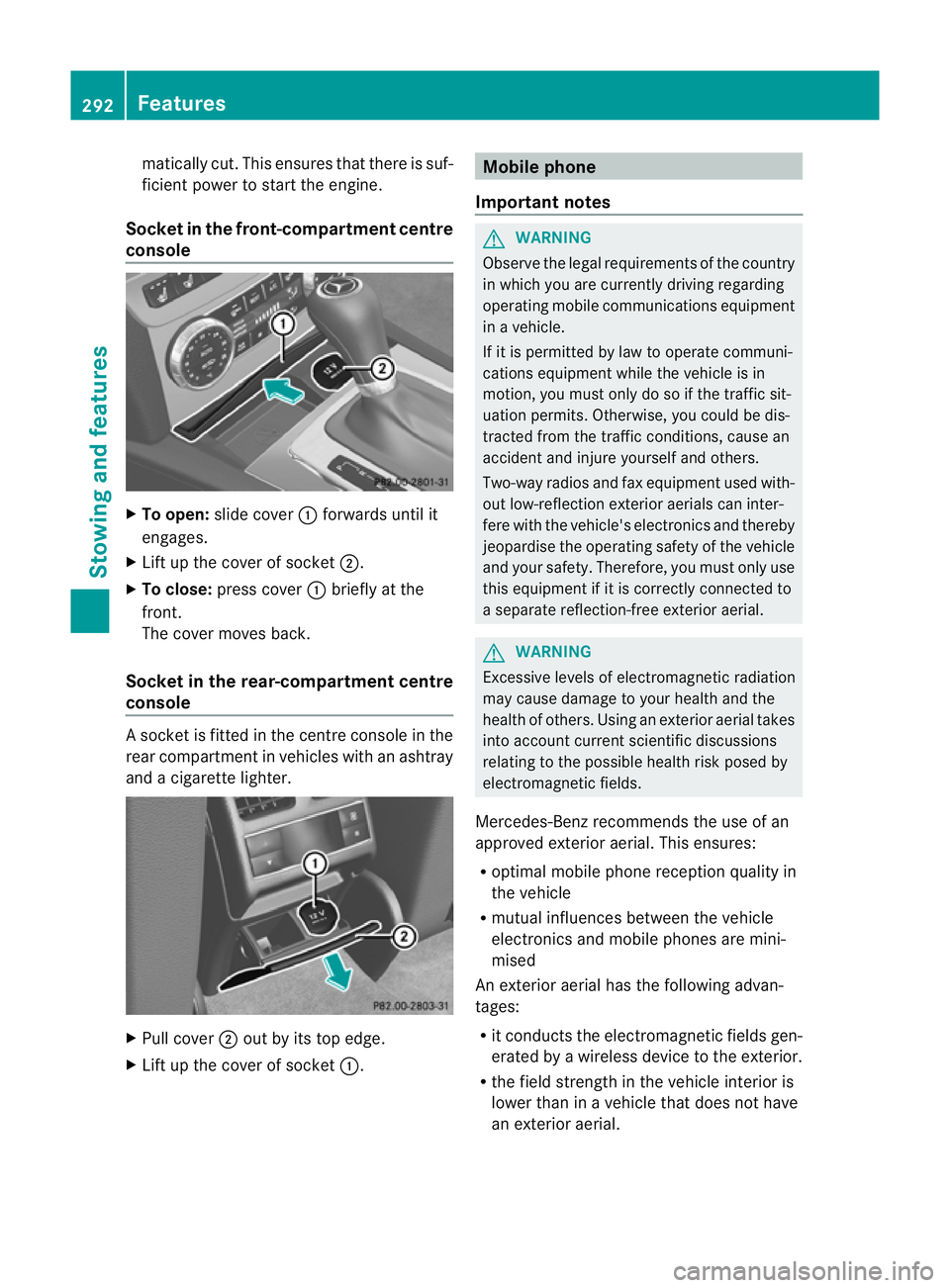
Socket in the front-compartment centre
console X
To open: slide cover :forwards until it
engages.
X Lift up the cover of socket ;.
X To close: press cover :briefly at the
front.
The cover moves back.
Socket in the rear-compartment centre
console As
ocket is fitted in the centre console in the
rear compartment in vehicles with an ashtray
and a cigarette lighter. X
Pull cover ;out by its top edge.
X Lift up the cover of socket :. Mobile phone
Important notes G
WARNING
Observe the legal requirements of the country
in which you are currently driving regarding
operating mobile communications equipment
in a vehicle.
If it is permitted by law to operate communi-
cations equipment while the vehicle is in
motion, you must only do so if the traffic sit-
uation permits. Otherwise, you could be dis-
tracted from the traffic conditions, cause an
accident and injure yourself and others.
Two-way radios and fax equipment used with-
out low-reflection exterior aerials can inter-
fere with the vehicle's electronics and thereby
jeopardise the operating safety of the vehicle
and your safety. Therefore, you must only use
this equipment if it is correctly connected to
a separate reflection-free exterior aerial. G
WARNING
Excessive levels of electromagnetic radiation
may cause damage to your health and the
health of others. Using an exterior aerial takes
into account current scientific discussions
relating to the possible health risk posed by
electromagnetic fields.
Mercedes-Benz recommends the use of an
approved exterior aerial. This ensures:
R optimal mobile phone reception quality in
the vehicle
R mutual influences between the vehicle
electronics and mobile phones are mini-
mised
An exterior aerial has the following advan-
tages:
R it conducts the electromagnetic fields gen-
erated by a wireless device to the exterior.
R the field strength in the vehicle interior is
lower than in a vehicle that does not have
an exterior aerial. 292
FeaturesStowing and features
Page 300 of 373

Frequencies for the garage door opener
The radio type approval number and the frequency range for the garage door opener can be
found on the Internet at: http://www.mercedes-benz.de/betriebsanleitung. Floormat on the driver's side
G
WARNING
Make sure that there is sufficien tclearance
around the pedals when floormats are used,
and that the floormats are properly secured.
The floormats must be correctly secured at all
times using retainers and press-studs.
Before you drive off, chec kthe floormats and
secure if necessary. Afloormat which is not
properly secured can slip and, thereby, inter-
fere with the movemen tofthe pedals.
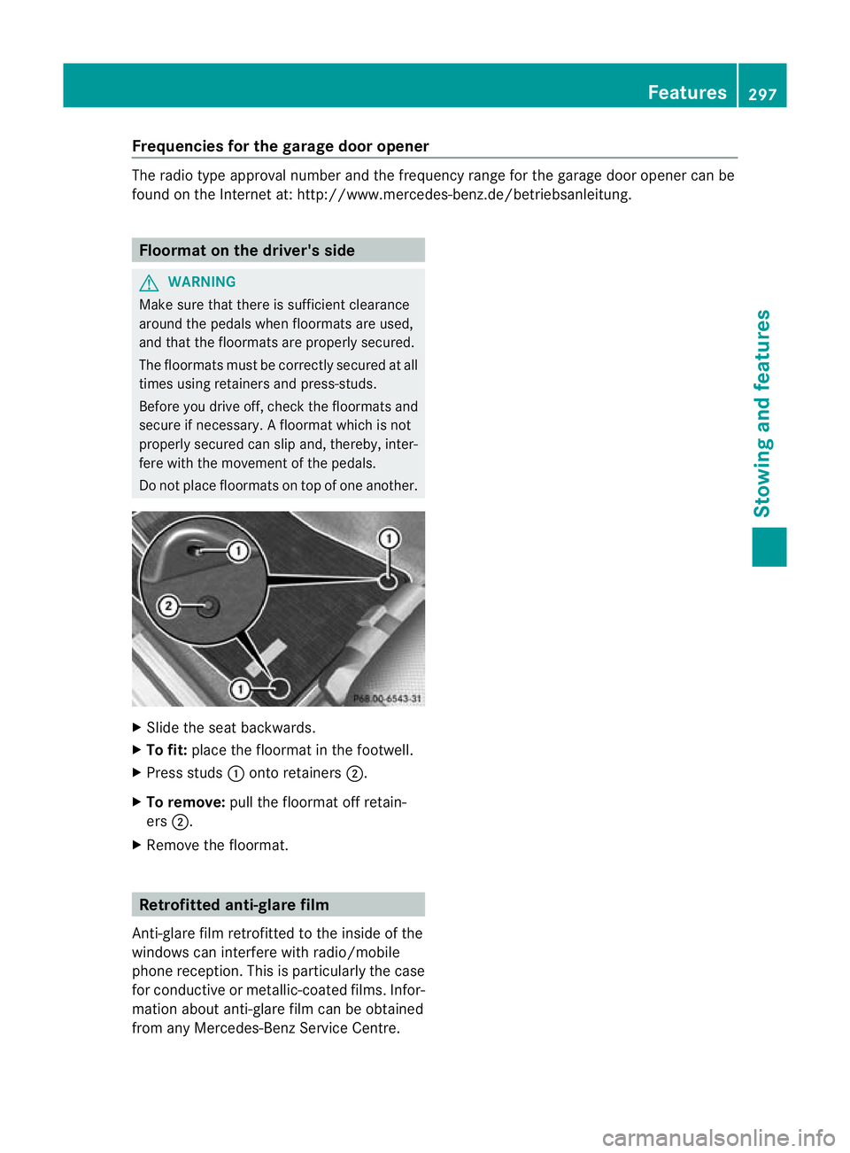
Do not place floormats on top of one another. X
Slide the seat backwards.
X To fit: place the floormat in the footwell.
X Press studs :onto retainers ;.
X To remove: pull the floormat off retain-
ers ;.
X Remove the floormat. Retrofitted anti-glare film
Anti-glare film retrofitted to the inside of the
windows can interfere with radio/mobile
phone reception. This is particularly the case
for conductive or metallic-coated films. Infor-
mation about anti-glare film can be obtained
from any Mercedes-Benz Service Centre. Features
297Stowing and features Z
Page 330 of 373

X
Apply the parking brake firmly and on vehi-
cles with automatic transmission, shift the
transmission to position P.
X Switch off all electrical consumers (e.g.
radio, blower, etc.).
X Turn the key to position 0(Y page 137) in
the ignition lock and remove it, or, on vehi-
cles with KEYLESS-GO ,make sure that the
ignition has been switched off
(Y page 137). All indicator lamps in the
instrument cluster must be off.
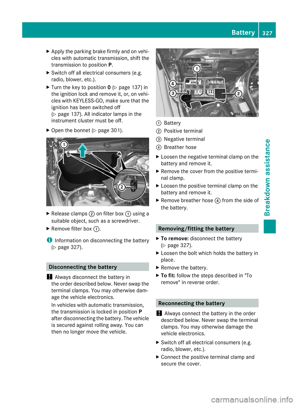
X Open the bonnet (Y page 301).X
Release clamps ;on filter box :using a
suitable object, such as a screwdriver.
X Remove filter box :.
i Information on disconnecting the battery
(Y page 327). Disconnecting the battery
! Always disconnect the battery in
the order described below. Never swap the
terminal clamps. You may otherwise dam-
age the vehicle electronics.
In vehicles with automatic transmission,
the transmission is locked in position P
after disconnecting the battery. The vehicle
is secured against rolling away. You can
then no longer move the vehicle. :
Battery
; Positive terminal
= Negative terminal
? Breather hose
X Loosen the negative terminal clamp on the
battery and remove it.
X Remove the cover from the positive termi-
nal clamp.
X Loosen the positive terminal clamp on the
battery and remove it.
X Remove breather hose ?from the side of
the battery. Removing/fitting the battery
X To remove: disconnect the battery
(Y page 327).
X Loosen the bolt which holds the battery in
place.
X Remove the battery.
X To fit: follow the steps described in "To
remove" in reverse order. Reconnecting the battery
! Always connect the battery in the order
described below. Never swap the terminal
clamps. You may otherwise damage the
vehicle electronics.
X Switch off all electrical consumers (e.g.
radio, blower, etc.).
X Connect the positive terminal clamp and
secure the cover. Battery
327Breakdown assistance Z
Page 332 of 373

Jump-starting
G
WARNING
There is a risk of acid burns when jump-starting a vehicle due to the gases which escape from
the battery. Do not lean over the battery while the engine is being jump-started. G
WARNING
Gases escaping from the battery during jump-starting may cause minor explosions. Avoid cre-
ating sparks. Keep naked flames away from the battery, and do not smoke.
Comply with safety precautions when handling batteries. You will find these under "Battery" in
the index.
! Avoid repeated and lengthy starting attempts. Otherwise, non-combusted fuel may dam-
age the catalytic converter 13
and create a risk of fire.
Do not use a rapid-charging device to start the engine.
Make sure the jump leads are not damaged.
Make sure the jump leads are not touching any other metal objects when they are connected
to the battery.
If your vehicle's battery is discharged, the engine can be jump-started from another vehicle
or from a second battery using jump leads.
Observe the following points:
X The battery is not accessible in all vehicles. If the other vehicle's battery is not accessible,
jump-start the vehicle using a second battery or ajump-starting device.
X Only jump-start the vehicle when the engine is cold and the catalyti cconverter system has
cooled down 14
.
X Do not start the engine if the battery is frozen. Let the battery thaw first.
X Jump-starting may only be performed from batteries with a nominal voltage of 12 V.
X Only use jump leads which have a sufficient cross-section and insulated terminal clamps.
X Make sure that the jump leads cannot come into contact with parts, such as the pulley or
the fan. These parts move when the engine is started and while it is running.
X If the battery is fully discharged, leave the battery that is being used to jump-start connected
for a few minutes before attempting to start.T his charges the empty battery a little.
i Jump leads and further information about jump-starting can be obtained from any
Mercedes-Benz Service Centre, for example.
X Make sure that the two vehicles do not touch.
X Apply the parking brake firmly.
X Manual transmission: engage neutral.
X Automatic transmission: move the selector lever toP.
X Switch off all electrical consumers (e.g. radio, blower, etc.).
X Open the bonnet (Y page 301).
13 Only vehicles with a petrol engine.
14 Only vehicles with a petrol engine. Jump-starting
329Breakdown assistance Z
Page 345 of 373

X
If the Tyre press. now OK? message
appears, use 9or: to select Can‐ cel .
X Press the abutton.
The tyre pressure values stored at the last
restart will continue to be monitored. Tyre pressure monitor
Important safety notes If a tyre pressure monitor system is fitted, the
vehicle's wheels have sensors fitted that
monitor the tyre pressures in all four tyres.
The tyre pressure monitor warns you when
the pressure drops in one or more of the
tyres. The tyre pressure monitor only func-
tions if the correct sensors are fitted to all
wheels.
G
WARNING
The tyre pressure monitor does not warn you
of an incorrectly set tyre pressure. The table
on the inside of the fuel fillerf lap will help you
decide whether the tyre pressures should be
corrected.
The tyre pressure monitor is not able to warn
you of a sudden loss of pressure, e.g. if the
tyre is penetrated by a foreign object. In the
even tofa sudden loss of pressure, bring the
vehicle to a halt by braking carefully.D o not
make any sudden steering movements when
doing so.
Information on tyre pressures is displayed in
the multifunction display .After a few minutes
of driving, the current tyre pressure of each
tyre is show ninthe multifunction display.
i The tyre pressure values indicated by the
on-board computer may differ from those
measured at a filling station with a pressure
gauge. The tyre pressures shown by the on-
board computer refer to those measured at
sea level. At high altitudes, the tyre pres-
sure values indicated by a pressure gauge
are higher than those shown by the on- board computer. In this case, do not reduce
the tyre pressures.
i The operation of the tyre pressure moni-
tor can be affected by interference from
radio transmitting equipment (e.g. radio
headphones, two-way radios) that may be
being operated in or near the vehicle.
Checking tyre pressure electronically X
Make sure that the key is in position 2
(Y page 137) in the ignition lock.
X Press the =or; button on the steer-
ing wheel to select the Service menu.
X Press the 9or: button to select
Tyre pressure .
X Press the abutton.
The current tyre pressure for each wheel
will be displayed in the multifunction dis-
play.
If the vehicle has been parked for longer than
20 minutes, the Tyre pressures will be
displayed after a few minutes of
driving message appears.
After a teach-in period, the tyre pressure
monitor automatically recognises new
wheels or new sensors. As long as a clear
allocation of the tyre pressure values to the
individual wheels is not possible, the Tyre pressure monitor active display mes-
sage is shown instead of the tyre pressure
display. The tyre pressures are already being
monitored.
i If a spare wheel/emergency spare wheel
is fitted, the system may continue to show
the tyre pressure of the wheel that has
been removed for a few minutes. If this
occurs, note that the value displayed for
the position where the spare wheel/emer-
gency spare wheel is fitted is not the same
as the spare wheel/emergency spare
wheel's current tyre pressure. 342
Tyre pressureWheels and tyres
Page 346 of 373

Tyre pressure monitor warning mes-
sages If the tyre pressure monitor detects a signifi-
cant pressure loss on one or more tyres, a
warning message is shown in the multifunc-
tio nd isplay. Awarning tone also sounds and
the tyre pressure warning lamp lights up in
the instrument cluster.
Each tyre that is affected by a significant loss
of pressure is highlighted in the pressure dis-
play.
If the Please correct tyre pressure message appears in the multifunction dis-
play:
X Chec kthe tyre pressure on all four wheels
and correct it if necessary.
i If the wheel positions on the vehicle are
interchanged, the tyre pressures may be
displayed for the wrong positions for a
short time. This is rectified after a few
minutes of driving, and the tyre pressures
are displayed for the correct positions.
Restarting the tyre pressure monitor When you restart the tyre pressure monitor,
all existing warning messages are deleted and
the warning lamps go out. The monitor uses
the currently set tyre pressures as the refer-
ence values for monitoring. In most cases, the
tyre pressure monitor will automatically
detect the new referencev alues after you
have changed the tyre pressure.
i For an overview of th emenus, see
(Y page 214).
If you wish to define the new reference values
manually:
X Use the table on the inside of the fuel filler
flap to ensure that the tyre pressure is set
correctly in all four tyres for the current
operating conditions. Also observe the notes in the section on
tyre pressures (Y
page 339).
X Make sure that the key is in position 2in
the ignition lock.
X Press the =or; button on the steer-
ing wheel to select the Service menu.
X Press the 9or: button to select
Tyre pressure .
X Press the abutton.
The multifunction display shows the cur-
rent tyre pressure of the individual tyres or
the Tyre pressures will be dis‐ played after a few minutes of driv‐
ing message.
X Press the :button.
The Use current pressures as new reference values message appears in
the multifunction display.
If you wish to confirm the restart:
X Press the abutton.
The Tyre press. monitor restarted message appears in the multifunction dis-
play.
After you have driven for a few minutes, the
system checks whether the current tyre
pressures are within the specified range.
The new tyre pressures are then accepted
as reference values and monitored.
If you wish to cancel the restart:
X Press the %button.
The tyre pressure values stored at the last
restart will continue to be monitored.
Radio type approval for the tyre pres-
sure monitor In certain countries, a radio type approval for
the tyre pressure monitor may be required.
The radio type approval number for the tyre
pressure monitor can be found online at:
http://www.mercedes-benz.de/
betriebsanleitung. Tyre pressure
343Wheels and tyres Z
Page 354 of 373

H
Environmental note
Daimler AG also supplies reconditioned
assemblies and parts which are of the same
quality as new parts. For these, the same war-
ranty applies as for new parts.
Always specify the vehicle identification num-
ber (VIN) (Y page 352) and the engine num-
ber (Y page 353) when ordering genuine
Mercedes-Ben zparts. Vehicle electronics
Tampering with the engine electron-
ics G
WARNING
Only have work on the engine electronics and
related components carried out at a qualified
specialist workshop which has the necessary
specialist knowledge and tools to carry out
the work required. Mercedes-Benz recom-
mends that you use a Mercedes-Ben zService
Centre for this purpose. In particular, work
relevant to safety or on safety-related sys-
tems must be carried out at a qualified spe-
cialist workshop. Otherwise, the vehicle's
roadworthiness could be affected.
! Only have maintenance work on the
engine electronics and its associated parts,
such as control units, sensors and connec-
tor leads, carried out at a qualified special-
ist workshop, e.g. a Mercedes-Benz Service
Centre. Vehicle componentsm ay other-
wise wear more quickly and the vehicle's
operating permit may be invalidated. Retrofitting of two-way radios and
mobile phones (RF transmitters)
Use the Technical Specification
ISO/TS 21609 22
implementation regulation
when retrofitting RF (radio frequency) trans-
mitters. If your vehicle has fittings for two-way radio
equipment, use the power supply or aerial
connections intended for use with the basic
wiring. Be sure to observe the manufacturer's
additional instructions when installing the fit-
tings.
!
Have aftermarket radio frequency trans-
mitting equipmen tinstalled at a qualified
specialist workshop .Mercedes-Benzr ec-
ommends that you use a Mercedes-Benz
Service Centre for this purpose.
The transmission output at the aerial base
must not exceed the maximum values below. Waveband Maximum trans-
mission output
(PEAK)
Short wave
(f < 54 MHz) 100 W
4 m waveband 30 W
2 m waveband 50 W
Trunked radio/Tetra 35 W
70 cm waveband 35 W
GSM 900/AMPS 10 W
GSM 1800 10 W
UMTS 10 W
The following aerial positions may be used if
RF transmitters have been properly installed:
22 ISO/TS 2160 9–Technical Specification for Road Vehicles (EMC) guidelines for installation of aftermarket
radio frequency transmitting equipment. Vehicle electronics
351Technical data Z