2011 INFINITI QX56 Vehicle security
[x] Cancel search: Vehicle securityPage 1 of 5598
A
B
D
E
F
G
H
I
J
K
L
M
N
P
O
C
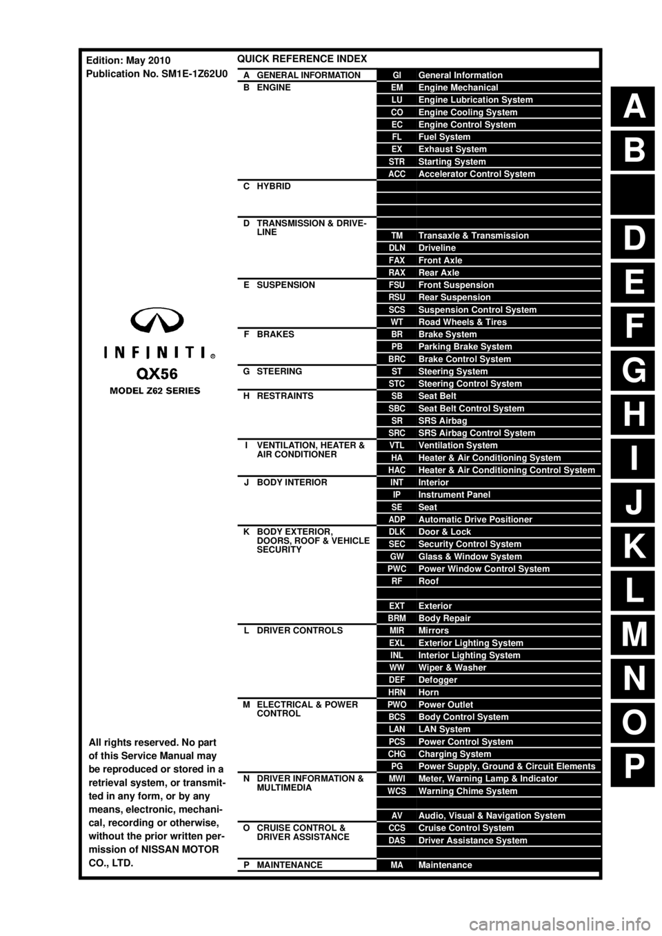
QUICK REFERENCE INDEX
AGENERAL INFORMATIONGIGeneral Information
BENGINEEMEngine Mechanical
LUEngine Lubrication System
COEngine Cooling System
ECEngine Control System
FLFuel System
EXExhaust System
STRStarting System
ACCAccelerator Control System
CHYBRIDHBCHybrid Control System
HBBHybrid Battery System
HBRHybrid Brake System
DTRANSMISSION & DRIVE-
LINECLClutch
TMTransaxle & Transmission
DLNDriveline
FAXFront Axle
RAXRear Axle
ESUSPENSIONFSUFront Suspension
RSURear Suspension
SCSSuspension Control System
WTRoad Wheels & Tires
FBRAKESBRBrake System
PBParking Brake System
BRCBrake Control System
GSTEERINGSTSteering System
STCSteering Control System
HRESTRAINTSSBSeat Belt
SBCSeat Belt Control System
SRSRS Airbag
SRCSRS Airbag Control System
IVENTILATION, HEATER &
AIR CONDITIONERVTLVentilation System
HAHeater & Air Conditioning System
HACHeater & Air Conditioning Control System
JBODY INTERIORINTInterior
IPInstrument Panel
SESeat
ADPAutomatic Drive Positioner
KBODY EXTERIOR,
DOORS, ROOF & VEHICLE
SECURITYDLKDoor & Lock
SECSecurity Control System
GWGlass & Window System
PWCPower Window Control System
RFRoof
HDHood
EXTExterior
BRMBody Repair
LDRIVER CONTROLSMIRMirrors
EXLExterior Lighting System
INLInterior Lighting System
WWWiper & Washer
DEFDefogger
HRNHorn
MELECTRICAL & POWER
CONTROLPWOPower Outlet
BCSBody Control System
LANLAN System
PCSPower Control System
CHGCharging System
PGPower Supply, Ground & Circuit Elements
NDRIVER INFORMATION &
MULTIMEDIAMWIMeter, Warning Lamp & Indicator
WCSWarning Chime System
SNSonar System
AVAudio, Visual & Navigation System
OCRUISE CONTROL &
DRIVER ASSISTANCECCSCruise Control System
DASDriver Assistance System
DMSDrive Mode System
PMAINTENANCEMAMaintenance
All rights reserved. No part
of this Service Manual may
be reproduced or stored in a
retrieval system, or transmit-
ted in any form, or by any
means, electronic, mechani-
cal, recording or otherwise,
without the prior written per-
mission of NISSAN MOTOR
CO., LTD.
Edition: May 2010
Publication No. SM1E-1Z62U0
Page 394 of 5598

BCS-6
< SYSTEM DESCRIPTION >
SYSTEM
SYSTEM
BODY CONTROL SYSTEM
BODY CONTROL SYSTEM : System DescriptionINFOID:0000000006274789
OUTLINE
BCM (Body Control Module) controls the various electrical components. It inputs the information required to
the control from CAN communication and the signal received from each switch and sensor.
BCM has combination switch reading function for reading the operation status of combination switches (light,
turn signal, wiper and washer) in addition to a function fo r controlling the operation of various electrical com-
ponents. It also has the signal transmission function as the passed point of signal and the power saving con-
trol function that reduces the power c onsumption with the ignition switch OFF.
BCM is equipped with the diagnosis function that perfo rms the diagnosis with CONSULT-III and various set-
tings.
BCM CONTROL FUNCTION LIST
System Reference
Combination switch reading system BCS-7, "
COMBINATION SWITCH READING SYSTEM : System
Diagram"
Signal buffer system
BCS-10, "SIGNAL BUFFER SYSTEM : System Diagram"
Power consumption control systemBCS-11, "POWER CONSUMPTION CONTROL SYSTEM : Sys-
tem Diagram"
Auto light system
EXL-11, "AUTO LIGHT SYSTEM : System Diagram"
Turn signal and hazard warning lamp systemEXL-18, "TURN SIGNAL AND HAZARD WARNING LAMP SYS-
TEM : System Diagram"
Headlamp system
EXL-10, "HEADLAMP SYSTEM : System Diagram"
Daytime running light systemEXL-14, "DAYTIME RUNNING LIGHT SYSTEM : System Dia-
gram"
Parking, license plate, side maker and tail lamps system
EXL-18, "PARKING, LICENSE PLATE, SIDE MARKER AND
TAIL LAMP SYSTEM : System Diagram"
Front fog lamp system
EXL-20, "FRONT FOG LAMP SYSTEM : System Diagram"
Exterior lamp battery saver systemEXL-20, "EXTERIOR LAMP BATTERY SAVER SYSTEM : Sys-
tem Diagram"
Interior room la
mp control system INL-6, "INTERIOR ROOM LAMP CONTROL SYSTEM : System
Diagram"
Interior room lamp battery saver system
INL-9, "INTERIOR ROOM LAMP BATTERY SAVER SYSTEM :
System Diagram"
Front wiper and washer systemWW-7, "FRONT WIPER AND WASHER SYSTEM : System Dia-
gram"
Rear wiper and washer systemWW-10, "REAR WIPER AND WASHER SYSTEM : System Dia-
gram"
Headlamp washer system
WW-13, "HEADLAMP WASHER SYSTEM : System Diagram"
Warning chime systemWCS-6, "WARNING CHIME SYSTEM : System Diagram"
Power door lock systemDLK-16, "System Diagram"
Infiniti Vehicle immobilizer System (IVIS)SEC-15, "INFINITI VEHICLE IMMOBILIZER SYSTEM-NATS :
System Diagram"
Vehicle security systemTheft warning alarm
SEC-17, "VEHICLE SECURITY SYSTEM : System Diagram"Panic alarm
Rear window defogger system DEF-6, "
System Diagram"
Intelligent Key system/engine start systemDLK-18, "INTELLIGENT KEY SYSTEM : System Diagram"
Power window system PWC-8, "SystemDiagram"
Retained accessory power (RAP) systemPWC-8, "System Description"
Revision: 2010 May2011 QX56
Page 400 of 5598

BCS-12
< SYSTEM DESCRIPTION >
SYSTEM
Low power consumption mode (BCM sleep)- Low power consumption control is active
- CAN transmission is stopped
LOW POWER CONSUMPTION CONTROL WITH BCM
BCM reduces the power consumption with the following operation in the low power consumption mode.
The reading interval of the each switches changes from 10 ms interval to 60 ms interval.
Sleep mode activation
BCM receives the sleep-ready signal (ready) from IPDM E/R, combination meter and automatic back door
control module via CAN communication.
BCM transmits the sleep wake up signal (sleep) to each unit when all of the CAN sleep conditions are ful- filled.
Each unit stops the transmission of CAN communication with the sleep wake up signal. BCM is in CAN com- munication sleep mode.
BCM is in the low power consumption mode and perform the low power consumption control when all of the
BCM sleep conditions are fulfilled with CAN sleep condition.
Sleep condition
Wake-up operation
BCM transmits sleep wake up signal (wake up) to eac h unit when any condition listed below is established,
and then goes into normal mode from low power consumption mode.
Each unit starts transmissions with CAN communication by receiving sleep wake up signals. Each unit trans- mit wake up signals to BCM with CAN communication to convey the start of CAN communication.
CAN sleep condition BCM sleep condition
Receiving the sleep-ready signal (ready) from all units
Ignition switch: OFF
Vehicle security system: Not operation
Warning chime: Not operation
Intelligent Key system buzzer: Not operation
Stop lamp switch: OFF
Turn signal indicator lamp: Not operation
Exterior lamp: OFF
Door lock status: No change
CONSULT-III communication status: Not communication
Meter display signal: Non-transmission
Door switch status: No change
Rear window defogger: OFF
Driver door lock status: No change Interior room lamp battery saver: Time out
RAP system: OFF
IVIS: Not operation
Remote keyless entry receiver communication status: No com-
munication
LOCK indicator lamp: Not operation
ACC indicator lamp: Not operation
ON indicator lamp: Not operation
Revision: 2010 May2011 QX56
Page 402 of 5598

BCS-14
< SYSTEM DESCRIPTION >
DIAGNOSIS SYSTEM (BCM)
DIAGNOSIS SYSTEM (BCM)
COMMON ITEM
COMMON ITEM : CONSULT-III Function (BCM - COMMON ITEM)INFOID:0000000006274796
APPLICATION ITEM
CONSULT-III performs the following functions via CAN communication with BCM.
SYSTEM APPLICATION
BCM can perform the following functions for each system.
NOTE:
It can perform the diagnosis modes except the following for all sub system selection items.
×: Applicable item
*: This item is indicated, but not used.
FREEZE FRAME DATA (FFD)
The BCM records the following vehicle condition at the time a particular DTC is detected, and displays on
CONSULT-III.
Diagnosis mode Function Description
Work Support Changes the setting for each system function.
Self Diagnostic Result Displays the diagnosis results judged by BCM. Refer to BCS-57, "
DTCIndex".
CAN Diag Support Monitor Monitors the reception status of CAN communication viewed from BCM. Refer to CONSULT-III opera-
tion manual.
Data Monitor The BCM input/output signals are displayed.
Active Test The signals used to activate ea ch device are forcibly supplied from BCM.
Ecu Identification The BCM part number is displayed.
Configuration Read and save the vehicle specification.
Write the vehicle specification when replacing BCM.
System Sub system selection item Diagnosis mode
Work Support Data Monitor Active Test
Door lock DOOR LOCK ×××
Rear window defogger REAR DEFOGGER ××
Warning chime BUZZER ××
Interior room lamp timer INT LAMP ×××
Exterior lamp HEAD LAMP ×××
Wiper and washer WIPER ×××
Turn signal and hazard warning lamps FLASHER ×××
— AIR CONDITONER* ××
Intelligent Key system
Engine start system INTELLIGENT KEY
×××
Combination switch COMB SW ×
Body control system BCM ×
IVIS IMMU ×××
Interior room lamp battery saver BATTERY SAVER ×××
Back door TRUNK ×
Vehicle security system THEFT ALM ×××
RAP system RETAINED PWR ×
Signal buffer system SIGNAL BUFFER ××
Revision: 2010 May2011 QX56
Page 417 of 5598

BCS
DIAGNOSIS SYSTEM (BCM)BCS-29
< SYSTEM DESCRIPTION >
C
DE
F
G H
I
J
K L
B A
O P
N
WORK SUPPORT
BATTERY SAVER
BATTERY SAVER : CONSULT-III Function (BCM - BATTERY SAVER)INFOID:0000000006376482
WORK SUPPORT
*:Factory setting
DATA MONITOR
Test item Description
THEFT IND This test is able to check security indicator lamp operation.
Security indicator lamp is turned on when “ON” on CONSULT-III screen touched.
Service item Description
CONFIRM DONGLE ID It is possible to check that dongle unit is applied to the vehicle.
Service item Setting item Setting
ROOM LAMP TIMER SET MODE 1
*30 min.
Sets the interior room lamp battery saver timer operating
time.
MODE 2 60 min.
BATTERY SAVER SET On
*With the exterior lamp battery saver function
Off Without the exterior lamp battery saver function
Monitor item [Unit] Description
REQ SW-DR
[On/Off] The switch status input from door request switch (driver side)
REQ SW-AS
[On/Off] The switch status input from door request switch (passenger side)
REQ SW-RR
[On/Off] NOTE:
The item is indicated, but not monitored.
REQ SW-RL
[On/Off]
PUSH SW
[On/Off] The switch status input from push-button ignition switch
UNLK SEN-DR
[On/Off] Driver door unlock status input from unlock sensor
DOOR SW-DR
[On/Off] The switch status input from door switch (driver side)
DOOR SW-AS
[On/Off] The switch status input from door switch (passenger side)
DOOR SW-RR
[On/Off] The switch status input from rear door switch RH
DOOR SW- RL
[On/Off] The switch status input from rear door switch LH
DOOR SW- BK
[On/Off] The switch status input from back door switch
CDL LOCK SW
[On/Off] Lock switch status input from door lock and unlock switch
CDL UNLOCK SW
[On/Off] Unlock switch status input from door lock and unlock switch
KEY CYL LK-SW
[On/Off] Lock switch status received from door key cylinder switch
Revision: 2010 May2011 QX56
Page 419 of 5598

BCS
DIAGNOSIS SYSTEM (BCM)BCS-31
< SYSTEM DESCRIPTION >
C
DE
F
G H
I
J
K L
B A
O P
N
WORK SUPPORT
ACTIVE TEST
RETAIND PWR
RETAIND PWR : CONSULT-III F
unction (BCM - RETAINED PWR)INFOID:0000000006376459
Data monitor
SIGNAL BUFFER
SIGNAL BUFFER : CONSULT-III F unction (BCM - SIGNAL BUFFER)INFOID:0000000006274818
DATA MONITOR
DOOR SW-RL Indicates [ON/OFF] condition of rear door switch LH.
DOOR SW-BK Indicates [ON/OFF] condition of back door switch.
CDL LOCK SW Indicates [ON/OFF] condition of lock signal from door lock/unlock switch LH and RH.
CDL UNLOCK SW Indicates [ON/OFF] condition of unlock signal from door lock/unlock switch LH and RH.
KEY CYL LK-SW Indicates [ON/OFF] condition of lock signal from door key cylinder.
KEY CYL UN-SW Indicates [ON/OFF] condition of unlock signal from door key cylinder.
TR/BD OPEN SW Indicates [ON/OFF] condition of back door opener switch.
TRNK/HAT MNTR NOTE:
This item is displayed, but cannot be monitored.
RKE-LOCK Indicates [ON/OFF] condition of LOCK signal from Intelligent Key.
RKE-UNLOCK Indicates [ON/OFF] condition of UNLOCK signal from Intelligent Key.
RKE-TR/BD NOTE:
This item is displayed, but cannot be monitored.
Monitored Item Description
Service Item Description
SECURITY ALARM SET This mode is able to confirm and change security alarm ON-OFF setting.
THEFT ALM TRG The switch which triggered vehicle security alarm is recorded.
This mode is able to confirm and erase the record of vehicle security alarm.
The trigger data can be erased by touching “CLEAR” on CONSULT-III screen.
Test Item Description
THEFT IND This test is able to check security indicator lamp operation. Security indicator lamp is turned on
when “ON” on CONSULT-III screen is touched.
VEHICLE SECURITY HORN This test is able to check horn operation. Horn is activated for 0.5 seconds after “ON” on CONSULT-
III screen is touched.
HEADLAMP(HI) This test is able to check headlamp operation. Headlamps are activated for 0.5 seconds after “ON”
on CONSULT-III screen is touched.
FLASHER This test is able to check hazard warning lamp operation. Hazard warning lamps are activated after
“ON” on CONSULT-III screen is touched.
Monitor Item Description
DOOR SW-DR Indicates [ON/OFF] condition of driver side door switch.
DOOR SW-AS Indicates [ON/OFF] condition of passenger side door switch.
Monitor item [UNIT] Description
PUSH SW
[Off/On] Displays the status of the push-button ignition switch (push switch) judged by BCM.
Revision: 2010 May2011 QX56
Page 676 of 5598

BRM-1
BODY EXTERIOR, DOORS, ROOF & VEHICLE SECURITY
C
D
E
F
G H
I
J
L
M
SECTION BRM
A
B
BRM
N
O P
CONTENTS
BODY REPAIR
VEHICLE INFORMATION ... ..........................2
BODY EXTERIOR PAINT COLOR ................ .....2
Body Exterior Paint Color ................................. ......2
PRECAUTION ...............................................4
REPAIRING HIGH STRENGTH STEEL ......... .....4
High Strength Steel (HSS) ................................ ......4
Handling of Ultra High Strength Steel Plate Parts ......6
PREPARATION ............................................7
REPAIRING MATERIAL ................................ .....7
Foam Repair ....................................................... ......7
BODY COMPONENT PARTS .............................9
Underbody Component Parts ............................ ......9
Body Component Parts ...........................................11
Frame Component Parts .........................................13
REMOVAL AND INSTALLATION ...............15
CORROSION PROTECTION ......................... ....15
Description .......................................................... ....15
Anti-corrosive Wax ..................................................15
Undercoating ...........................................................16
Stone Guard Coat ...................................................17
Body Sealing ...........................................................18
BODY CONSTRUCTION ....................................22
Body Construction ............................................... ....22
REPLACEMENT OPERATIONS .......................24
Description ...............................................................24
Radiator Core Support .............................................26
Hoodledge ...............................................................26
Hoodledge (Partial Replacement) ...........................27
Front Pillar ...............................................................29
Center Pillar .............................................................32
Outer Sill .................................................................35
Rear Fender ............................................................39
Rear Fender Extension ............................................42
Rear Panel and Rear End Crossmember ................42
Rear Floor Rear .....................................................45
Crush Horn ..............................................................46
SERVICE DATA AND SPECIFICATIONS
(SDS) ............... .............................................
48
BODY ALIGNMENT ..........................................48
Body Center Marks ............................................ ....48
Description ...............................................................48
Engine Compartment ..............................................49
Underbody ...............................................................52
Passenger Compartment .........................................54
Rear Body ...............................................................56
LOCATION OF PLASTIC PARTS ....................58
Precautions for Plastics ...........................................58
Location of Plastic Parts ..........................................59
Revision: 2010 May2011 QX56
Page 1499 of 5598
DIAGNOSIS SYSTEM (BCM)DEF-7
< SYSTEM DESCRIPTION >
C
DE
F
G H
I
J
K
M A
B
DEF
N
O P
DIAGNOSIS SYSTEM (BCM)
COMMON ITEM
COMMON ITEM : CONSULT-III Fu nction (BCM - COMMON ITEM)INFOID:0000000006349773
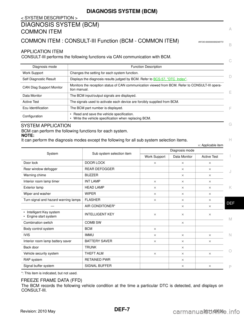
APPLICATION ITEM
CONSULT-III performs the following functions via CAN communication with BCM.
SYSTEM APPLICATION
BCM can perform the following functions for each system.
NOTE:
It can perform the diagnosis modes except the following for all sub system selection items.
×: Applicable item
*: This item is indicated, but not used.
FREEZE FRAME DATA (FFD)
The BCM records the following vehicle condition at the time a particular DTC is detected, and displays on
CONSULT-III.
Diagnosis mode Function Description
Work Support Changes the setting for each system function.
Self Diagnostic Result Displays the diagnosis results judged by BCM. Refer to BCS-57, "
DTCIndex".
CAN Diag Support Monitor Monitors the reception status of CAN communication viewed from BCM. Refer to CONSULT-III opera-
tion manual.
Data Monitor The BCM input/output signals are displayed.
Active Test The signals used to activate each device are forcibly supplied from BCM.
Ecu Identification The BCM part number is displayed.
Configuration Read and save the vehicle specification.
Write the vehicle specification when replacing BCM.
System Sub system selection item Diagnosis mode
Work Support Data Monitor Active Test
Door lock DOOR LOCK ×××
Rear window defo gger REAR DEFOGGER ××
Warning chime BUZZER ××
Interior room lamp timer INT LAMP ×××
Exterior lamp HEAD LAMP ×××
Wiper and washer WIPER ×××
Turn signal and hazard warning lamps FLASHER ×××
— AIR CONDITONER* ××
Intelligent Key system
Engine start system INTELLIGENT KEY
×××
Combination switch COMB SW ×
Body control system BCM ×
IVIS IMMU ×××
Interior room lamp battery saver BATTERY SAVER ×××
Back door TRUNK ×
Vehicle security system THEFT ALM ×××
RAP system RETAINED PWR ×
Signal buffer system SIGNAL BUFFER ××
Revision: 2010 May2011 QX56