2011 INFINITI QX56 door
[x] Cancel search: doorPage 4766 of 5598
PRECAUTIONSSR-3
< PRECAUTION >
C
DE
F
G
I
J
K L
M A
B
SR
N
O P
5. When the repair work is completed, re-connect both battery cables. With the brake pedal released, turn
the push-button ignition switch from ACC position to ON position, then to LOCK position. (The steering
wheel will lock when the push-button ignition switch is turned to LOCK position.)
6. Perform self-diagnosis check of a ll control units using CONSULT-III.
Precaution for Battery ServiceINFOID:0000000006113045
Before disconnecting the battery, lower both the driver and passenger windows. This will prevent any interfer-
ence between the window edge and the vehicle when the door is opened/closed. During normal operation, the
window slightly raises and lowers automatically to prev ent any window to vehicle interference. The automatic
window function will not work with the battery disconnected.
Occupant Classification SystemINFOID:0000000006113047
Replace occupant classification system control uni t and passenger front seat cushion as an assembly.
Refer to SE-105, "
Exploded View".
ServiceINFOID:0000000006113046
Never use electrical test equipment to check SRS circuits unless instructed to in this Service Manual.
Before servicing the SRS, turn ignition switch OFF, disconnect battery negative terminal and wait at least 3
minutes.
For approximately 3 minutes after the battery negative termi nal is removed, it is still possible for the air bag
and seat belt pre-tensioner to deploy. Therefore, never work on any SRS connectors or wires until at least 3
minutes have elapsed.
Diagnosis sensor unit must always be installed with their arrow marks “ ⇐” pointing towards the front of the
vehicle for proper operation. Also check diagnosis sensor unit for cracks, deformities, or rust before installa-
tion and replace as required.
The spiral cable must be aligned in the neutral position since its rotations are limited. Never turn steering
wheel and column after removal of steering gear.
Handle air bag module carefully. Always place driver and front passenger air bag modules with the pad side facing upward and seat mounted front side air bag m odule standing with the stud bolt side facing downward.
Perform self-diagnosis to check entire SRS fo r proper function after replacing any components.
After air bag deploys, the front instrument panel assembly should be replaced if damaged.
Always replace instrument panel pad following front passenger air bag deployment.
Revision: 2010 May2011 QX56
Page 4770 of 5598
COLLISION DIAGNOSISSR-7
< BASIC INSPECTION >
C
DE
F
G
I
J
K L
M A
B
SR
N
O P
FOR SIDE AND ROLLOVER COLLISION
FOR SIDE AND ROLLOVER CO LLISION : When SRS is activated in a collision
INFOID:0000000006113082
CAUTION:
Due to varying models and option levels, not all parts listed in the chart below apply to all vehicles.
WORK PROCEDURE
1. Before performing any of the following steps, ensur e that all vehicle body and structural repairs have been
completed.
2. Replace the following components: Front seat back assembly (on the side on which side air bag is activated)
Door finisher (on the side on which door-mounted curtain air bag is activated)
Pop-up roll bar assemblies and pop-up roll bar covers
Side air bag (satellite) sensor LH/RH (on the side on which side air bag is activated)
Diagnosis sensor unit
Seat belt pre-tensioner assemblies
3. Check the SRS components and the related parts using the following table. Replace any SRS components and the related parts s howing visible signs of damage. (dents, cracks,
deformation, etc.)
4. Perform self-diagnosis using CONSULT-III and “AIR BAG” warning lamp. Refer to SRC-14, "
Description"
for details. Make sure entire SRS operates properly.
5. After the work is completed, perform self-diagnosis to check that no malfunction is detected. Refer to
SRC-14, "
Description".
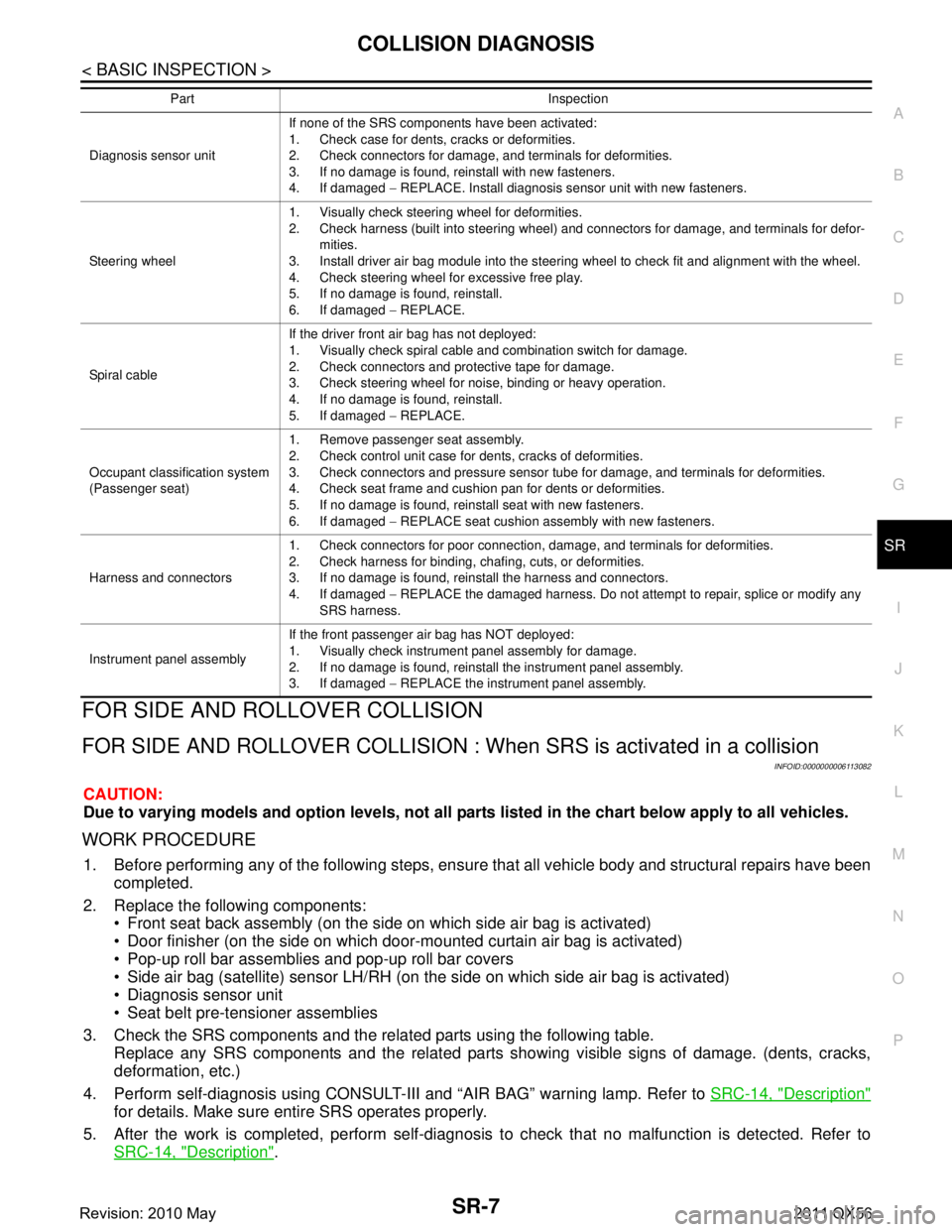
Diagnosis sensor unit If none of the SRS components have been activated:
1. Check case for dents, cracks or deformities.
2. Check connectors for damage, and terminals for deformities.
3. If no damage is found, reinstall with new fasteners.
4. If damaged
− REPLACE. Install diagnosis sensor unit with new fasteners.
Steering wheel 1. Visually check steering wheel for deformities.
2. Check harness (built into steering wheel) and connectors for damage, and terminals for defor-
mities.
3. Install driver air bag module into the steering wheel to check fit and alignment with the wheel.
4. Check steering wheel for excessive free play.
5. If no damage is found, reinstall.
6. If damaged − REPLACE.
Spiral cable If the driver front air bag has not deployed:
1. Visually check spiral cable and combination switch for damage.
2. Check connectors and protective tape for damage.
3. Check steering wheel for noise, binding or heavy operation.
4. If no damage is found, reinstall.
5. If damaged
− REPLACE.
Occupant classification system
(Passenger seat) 1. Remove passenger seat assembly.
2. Check control unit case for dents, cracks of deformities.
3. Check connectors and pressure sensor tube for damage, and terminals for deformities.
4. Check seat frame and cushion pan for dents or deformities.
5. If no damage is found, reinstall seat with new fasteners.
6. If damaged
− REPLACE seat cushion assembly with new fasteners.
Harness and connectors 1. Check connectors for poor connection, damage, and terminals for deformities.
2. Check harness for binding, chafing, cuts, or deformities.
3. If no damage is found, reinstall the harness and connectors.
4. If damaged
− REPLACE the damaged harness. Do not attempt to repair, splice or modify any
SRS harness.
Instrument panel assembly If the front passenger air bag has NOT deployed:
1. Visually check instrument panel assembly for damage.
2. If no damage is found, reinstall the instrument panel assembly.
3. If damaged
− REPLACE the instrument panel assembly.
Part Inspection
Revision: 2010 May2011 QX56
Page 4771 of 5598
SR-8
< BASIC INSPECTION >
COLLISION DIAGNOSIS
SRS INSPECTION (FOR SIDE AND ROLLOVER COLLISION)
FOR SIDE AND ROLLOVER COLLISION : When SRS is not activated in a collision
INFOID:0000000006113083
CAUTION:
Due to varying models and option levels, not all part s listed in the chart below apply to all vehicles.
WORK PROCEDURE
1. Before performing any of the following steps, ensur e that all vehicle body and structural repairs have been
completed.
2. Check the SRS components and the related parts using the following table. If the front seat back assembly is damaged, t he front seat back assembly must be replaced.
If the door finisher assembly is damaged, the door finisher assembly and door-mounted curtain air bag
module must be replaced.
3. Perform self-diagnosis using CONSULT-III and “AIR BAG” warning lamp. Refer to SRC-14, "
Description"
for details. Make sure entire SRS operates properly.
4. After the work is completed, perform self-diagnosis to check that no malfunction is detected. Refer to
SRC-14, "
Description".
SRS INSPECTION (FOR SIDE AND ROLLOVER COLLISION)
Part Inspection
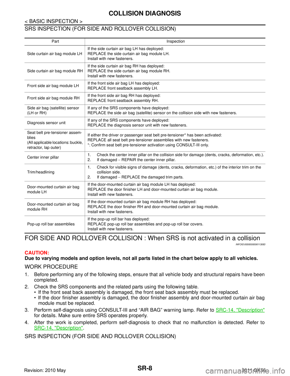
Side curtain air bag module LH If the side curtain air bag LH has deployed:
REPLACE the side curtain air bag module LH.
Install with new fasteners.
Side curtain air bag module RH If the side curtain air bag RH has deployed:
REPLACE the side curtain air bag module RH.
Install with new fasteners.
Front side air bag module LH If the front side air bag LH has deployed:
REPLACE front seatback assembly LH.
Front side air bag module RH If the front side air bag RH has deployed:
REPLACE front seatback assembly RH.
Side air bag (satellite) sensor
(LH or RH) If any of the SRS components have deployed:
REPLACE the side air bag (satellite) sensor on the collision side with new fasteners.
Diagnosis sensor unit If any of the SRS components have deployed:
REPLACE the diagnosis sensor unit with new fasteners.
Seat belt pre-tensioner assem-
blies
(All applicable locations: buckle,
retractor, lap outer) If either the driver or passenger seat belt pre-tensioner* has been activated:
REPLACE all seat belt pre-tensioner assemblies with new fasteners.
*: Confirm seat belt pre-tensioner activation using CONSULT-III only.
Center inner pillar 1. Check the center inner pillar on the collision side for damage (dents, cracks, deformation, etc.).
2. If damaged
− REPAIR the center inner pillar.
Trim/headlining 1. Check for visible signs of damage (dents, cracks, deformation, etc.) of the interior trim on the
collision side.
2. If damaged − REPLACE the damaged trim parts.
Door-mounted curtain air bag
module LH If the door-mounted curtain air bag module LH has deployed:
REPLACE the door finisher LH and door-mounted curtain air bag module.
Install with new fasteners.
Door-mounted curtain air bag
module RH If the door-mounted curtain air bag module RH has deployed:
REPLACE the door finisher RH and door-mounted curtain air bag module.
Install with new fasteners.
Pop-up roll bar assemblies If the pop-up roll bar has deployed:
REPLACE pop-up roll bar assemblies and pop-up roll bar covers.
Install with new fasteners.
Revision: 2010 May2011 QX56
Page 4773 of 5598
SR-10
< BASIC INSPECTION >
COLLISION DIAGNOSIS
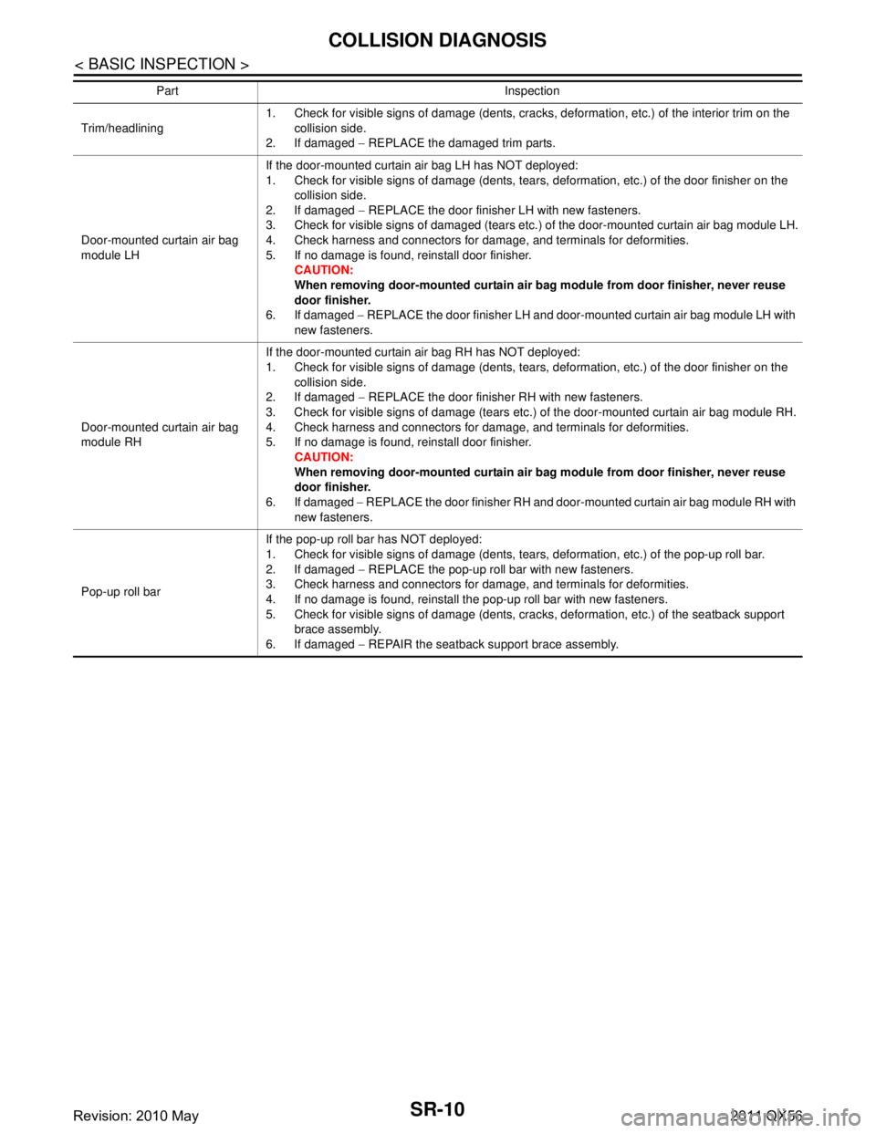
Trim/headlining1. Check for visible signs of damage (dents, cracks, deformation, etc.) of the interior trim on the
collision side.
2. If damaged − REPLACE the damaged trim parts.
Door-mounted curtain air bag
module LH If the door-mounted curtain air bag LH has NOT deployed:
1. Check for visible signs of damage (dents, tears, deformation, etc.) of the door finisher on the
collision side.
2. If damaged − REPLACE the door finisher LH with new fasteners.
3. Check for visible signs of damaged (tears etc.) of the door-mounted curtain air bag module LH.
4. Check harness and connectors for damage, and terminals for deformities.
5. If no damage is found, reinstall door finisher. CAUTION:
When removing door-mounted curtain air bag module from door finisher, never reuse
door finisher.
6. If damaged − REPLACE the door finisher LH and door-mounted curtain air bag module LH with
new fasteners.
Door-mounted curtain air bag
module RH If the door-mounted curtain air bag RH has NOT deployed:
1. Check for visible signs of damage (dents, tears, deformation, etc.) of the door finisher on the
collision side.
2. If damaged − REPLACE the door finisher RH with new fasteners.
3. Check for visible signs of damage (tears etc.) of the door-mounted curtain air bag module RH.
4. Check harness and connectors for damage, and terminals for deformities.
5. If no damage is found, reinstall door finisher. CAUTION:
When removing door-mounted curtain air bag module from door finisher, never reuse
door finisher.
6. If damaged − REPLACE the door finisher RH and door-mounted curtain air bag module RH with
new fasteners.
Pop-up roll bar If the pop-up roll bar has NOT deployed:
1. Check for visible signs of damage (dents, tears, deformation, etc.) of the pop-up roll bar.
2. If damaged
− REPLACE the pop-up roll bar with new fasteners.
3. Check harness and connectors for damage, and terminals for deformities.
4. If no damage is found, reinstall the pop-up roll bar with new fasteners.
5. Check for visible signs of damage (dents, cracks, deformation, etc.) of the seatback support brace assembly.
6. If damaged − REPAIR the seatback support brace assembly.
Part Inspection
Revision: 2010 May2011 QX56
Page 4969 of 5598
SRC-176
< DTC/CIRCUIT DIAGNOSIS >
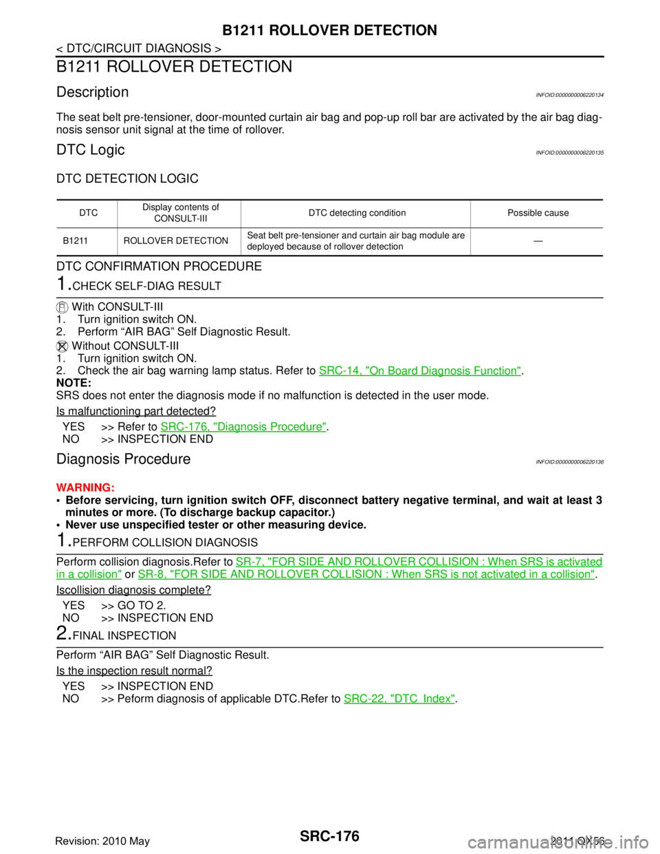
B1211 ROLLOVER DETECTION
B1211 ROLLOVER DETECTION
DescriptionINFOID:0000000006220134
The seat belt pre-tensioner, door-mounted curtain air bag and pop-up roll bar are activated by the air bag diag-
nosis sensor unit signal at the time of rollover.
DTC LogicINFOID:0000000006220135
DTC DETECTION LOGIC
DTC CONFIRMATION PROCEDURE
1.CHECK SELF-DIAG RESULT
With CONSULT-III
1. Turn ignition switch ON.
2. Perform “AIR BAG” Self Diagnostic Result.
Without CONSULT-III
1. Turn ignition switch ON.
2. Check the air bag warning lamp status. Refer to SRC-14, "
On Board Diagnosis Function".
NOTE:
SRS does not enter the diagnosis mode if no malfunction is detected in the user mode.
Is malfunctioning part detected?
YES >> Refer to SRC-176, "Diagnosis Procedure".
NO >> INSPECTION END
Diagnosis ProcedureINFOID:0000000006220136
WARNING:
Before servicing, turn ignition sw itch OFF, disconnect battery negative terminal, and wait at least 3
minutes or more. (To discharge backup capacitor.)
Never use unspecified tester or other measuring device.
1.PERFORM COLLISION DIAGNOSIS
Perform collision diagnosis.Refer to SR-7, "
FOR SIDE AND ROLLOVER COLLISI ON : When SRS is activated
in a collision" or SR-8, "FOR SIDE AND ROLLOVER COLLISION : When SRS is not activated in a collision".
Iscollision diagnosis complete?
YES >> GO TO 2.
NO >> INSPECTION END
2.FINAL INSPECTION
Perform “AIR BAG” Self Diagnostic Result.
Is the inspection result normal?
YES >> INSPECTION END
NO >> Peform diagnosis of applicable DTC.Refer to SRC-22, "
DTCIndex".
DTCDisplay contents of
CONSULT-III DTC detecting condition Possible cause
B1211 ROLLOVER DETECTION Seat belt pre-tensioner and curtain air bag module are
deployed because of rollover detection —
Revision: 2010 May2011 QX56
Page 5401 of 5598
BLOWER UNITVTL-15
< REMOVAL AND INSTALLATION >
C
DE
F
G H
J
K L
M A
B
VTL
N
O P
Removal and InstallationINFOID:0000000006276306
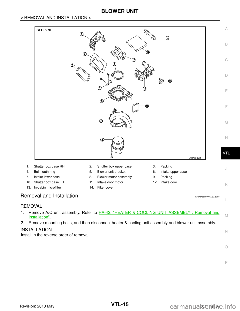
REMOVAL
1. Remove A/C unit assembly. Refer to HA-42, "HEATER & COOLING UNIT ASSEMBLY : Removal and
Installation".
2. Remove mounting bolts, and then disconnect heater & cooling unit assembly and blower unit assembly.
INSTALLATION
Install in the reverse order of removal.
1. Shutter box case RH 2. Shutter box upper case 3. Packing
4. Bellmouth ring 5. Blower unit bracket 6. Intake upper case
7. Intake lower case 8. Blower motor assembly 9. Packing
10. Shutter box case LH 11. Intake door motor 12. Intake door
13. In-cabin microfilter 14. Filter cover
JMIIA0642ZZ
Revision: 2010 May2011 QX56
Page 5410 of 5598
WCS-6
< SYSTEM DESCRIPTION >
SYSTEM
SYSTEM
WARNING CHIME SYSTEM
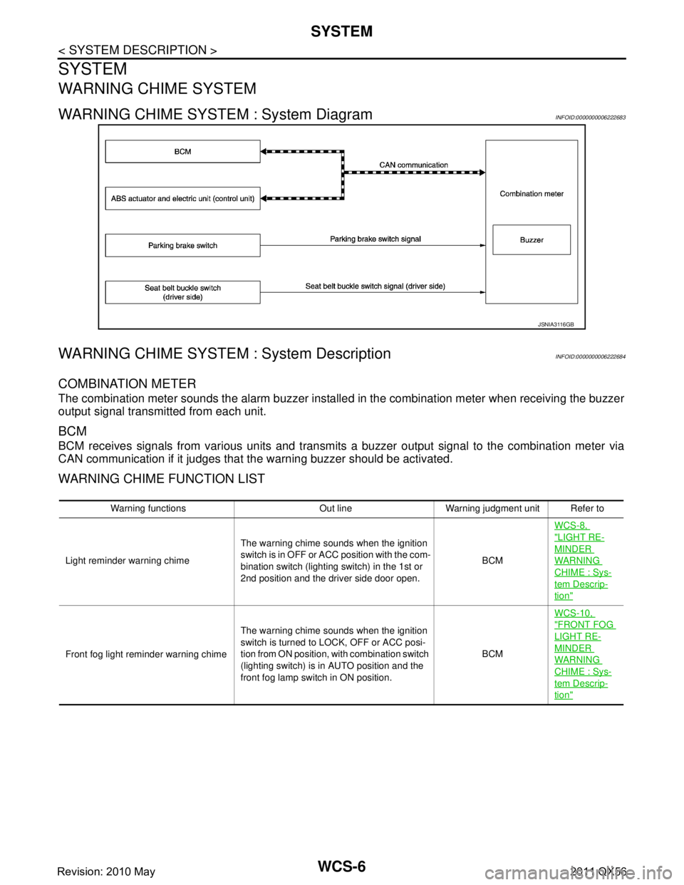
WARNING CHIME SYSTEM : System DiagramINFOID:0000000006222683
WARNING CHIME SYSTEM : System DescriptionINFOID:0000000006222684
COMBINATION METER
The combination meter sounds the alarm buzzer install ed in the combination meter when receiving the buzzer
output signal transmitted from each unit.
BCM
BCM receives signals from various units and transmits a buzzer output signal to the combination meter via
CAN communication if it judges that the warning buzzer should be activated.
WARNING CHIME FUNCTION LIST
JSNIA3116GB
Warning functions Out line Warning judgment unit Refer to
Light reminder warning chime The warning chime sounds when the ignition
s w i t c h i s i n O F F o r A C C p o s i t i o n w i t h t h e c o m -
bination switch (lighting switch) in the 1st or
2nd position and the driver side door open. BCMWCS-8,
"LIGHT RE-
MINDER
WARNING
CHIME : Sys-
tem Descrip-
tion"
Front fog light reminder warning chime
The warning chime sounds when the ignition
switch is turned to LOCK, OFF or ACC posi-
tion from ON position, with combination switch
(lighting switch) is in AUTO position and the
front fog lamp switch in ON position. BCMWCS-10,
"FRONT FOG
LIGHT RE-
MINDER
WARNING
CHIME : Sys-
tem Descrip-
tion"
Revision: 2010 May2011 QX56
Page 5411 of 5598
WCS
SYSTEMWCS-7
< SYSTEM DESCRIPTION >
C
DE
F
G H
I
J
K L
M B A
O P
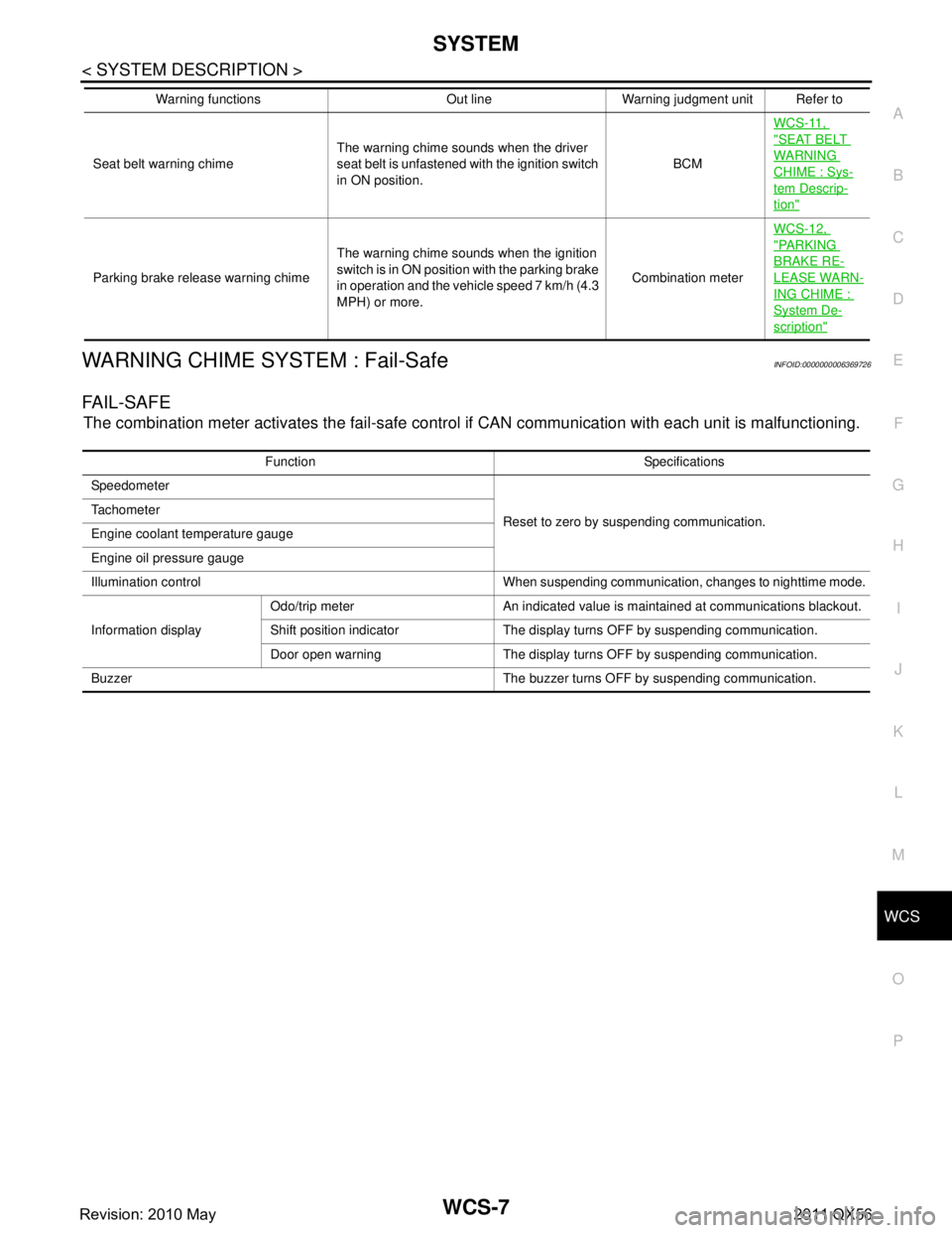
WARNING CHIME SYSTEM : Fail-SafeINFOID:0000000006369726
FA I L - S A F E
The combination meter activates the fail-safe contro l if CAN communication with each unit is malfunctioning.
Seat belt warning chimeThe warning chime sounds when the driver
seat belt is unfastened with the ignition switch
in ON position. BCMWCS-11,
"SEAT BELT
WARNING
CHIME : Sys-
tem Descrip-
tion"
Parking brake release warning chime
The warning chime sounds when the ignition
switch is in ON position with the parking brake
in operation and the vehicle speed 7 km/h (4.3
MPH) or more. Combination meterWCS-12,
"PA R K I N G
BRAKE RE-
LEASE WARN-
ING CHIME :
System De-
scription"
Warning functions Out line Warning judgment unit Refer to
Function Specifications
Speedometer
Reset to zero by suspending communication.
Tachometer
Engine coolant temperature gauge
Engine oil pressure gauge
Illumination control When suspending communication, changes to nighttime mode.
Information display Odo/trip meter An indicated value is maintained at communications blackout.
Shift position indicator The display turns OFF by suspending communication.
Door open warning The display turns OFF by suspending communication.
Buzzer The buzzer turns OFF by suspending communication.
Revision: 2010 May2011 QX56