2011 INFINITI QX56 height
[x] Cancel search: heightPage 2643 of 5598
CAMSHAFTEM-81
< REMOVAL AND INSTALLATION >
C
DE
F
G H
I
J
K L
M A
EM
NP
O
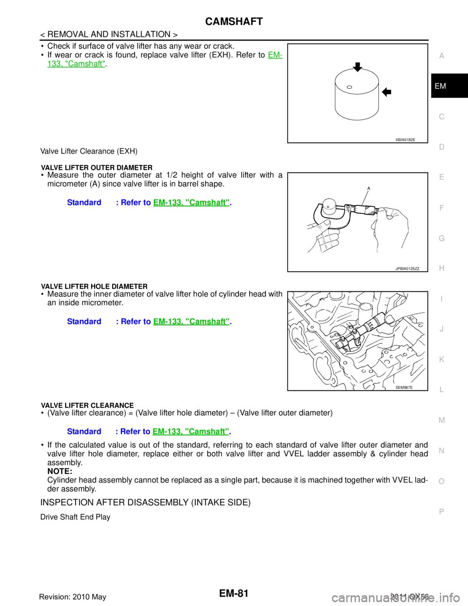
Check if surface of valve lifter has any wear or crack.
If wear or crack is found, replace valve lifter (EXH). Refer to
EM-
133, "Camshaft".
Valve Lifter Clearance (EXH)
VALVE LIFTER OUTER DIAMETER Measure the outer diameter at 1/2 height of valve lifter with a
micrometer (A) since valve lifter is in barrel shape.
VALVE LIFTER HOLE DIAMETER Measure the inner diameter of va lve lifter hole of cylinder head with
an inside micrometer.
VALVE LIFTER CLEARANCE (Valve lifter clearance) = (Valve lifter hole diameter) – (Valve lifter outer diameter)
If the calculated value is out of the standard, referr ing to each standard of valve lifter outer diameter and
valve lifter hole diameter, replace either or both valve lifter and VVEL ladder assembly & cylinder head
assembly.
NOTE:
Cylinder head assembly cannot be replaced as a single pa rt, because it is machined together with VVEL lad-
der assembly.
INSPECTION AFTER DISASSEMBLY (INTAKE SIDE)
Drive Shaft End Play
KBIA0182E
Standard : Refer to EM-133, "Camshaft".
JPBIA0125ZZ
Standard : Refer to EM-133, "Camshaft".
SEM867E
Standard : Refer to EM-133, "Camshaft".
Revision: 2010 May2011 QX56
Page 2645 of 5598
CAMSHAFTEM-83
< REMOVAL AND INSTALLATION >
C
DE
F
G H
I
J
K L
M A
EM
NP
O
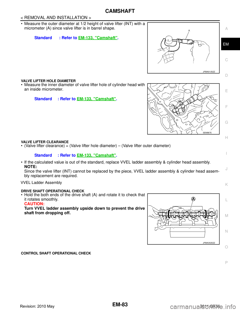
Measure the outer diameter at 1/2
height of valve lifter (INT) with a
micrometer (A) since valve lifter is in barrel shape.
VALVE LIFTER HOLE DIAMETER Measure the inner diameter of va lve lifter hole of cylinder head with
an inside micrometer.
VALVE LIFTER CLEARANCE (Valve lifter clearance) = (Valve lifter hole diameter) – (Valve lifter outer diameter)
If the calculated value is out of the standard, r eplace VVEL ladder assembly & cylinder head assembly.
NOTE:
Since the valve lifter (INT) cannot be replaced by t he piece, VVEL ladder assembly & cylinder head assem-
bly replacement are required.
VVEL Ladder Assembly
DRIVE SHAFT OPERATIONAL CHECK Hold the both ends of the drive shaft (A) and rotate it to check that it rotates smoothly.
CAUTION:
Turn VVEL ladder assembly upside down to prevent the drive
shaft from dropping off.
CONTROL SHAFT OPERATIONAL CHECK
Standard : Refer to EM-133, "Camshaft".
JPBIA0125ZZ
Standard : Refer to EM-133, "Camshaft".
SEM867E
Standard : Refer to EM-133, "Camshaft".
JPBIA3520ZZ
Revision: 2010 May2011 QX56
Page 2654 of 5598
![INFINITI QX56 2011 Factory Service Manual
EM-92
< REMOVAL AND INSTALLATION >
CYLINDER HEAD
a. Apply new engine oil on new valve oil seal joint and seal lip.
b. Using the valve oil seal drift [SST: KV10115600 (J-38958)] (A),press fit valve se INFINITI QX56 2011 Factory Service Manual
EM-92
< REMOVAL AND INSTALLATION >
CYLINDER HEAD
a. Apply new engine oil on new valve oil seal joint and seal lip.
b. Using the valve oil seal drift [SST: KV10115600 (J-38958)] (A),press fit valve se](/manual-img/42/57033/w960_57033-2653.png)
EM-92
< REMOVAL AND INSTALLATION >
CYLINDER HEAD
a. Apply new engine oil on new valve oil seal joint and seal lip.
b. Using the valve oil seal drift [SST: KV10115600 (J-38958)] (A),press fit valve seal to height (b) shown in figure.
4. Install valve. NOTE:
Larger diameter valves are for intake side.
5. Install valve spring (with valve spring seat). Install narrow pitch (B) end [paint mark (C)] to cylinder headside (valve spring seat side).
6. Install valve spring retainer.
7. Install valve collet. Compress valve spring with the valve spring compressor [SST:
KV10116200 (J26336-A)] (A), the attachment [SST:
KV10115900 (J26336-20)] (C) and the adapter [SST:
KV10109220 ( — )] (B). Install valve collet with a magnet
hand.
CAUTION:
When working, take care not to damage valve lifter holes.
Tap valve stem edge lightly with plastic hammer after installa- tion to check its installed condition.
InspectionINFOID:0000000006289573
INSPECTION AFTER DISASSEMBLY
Cylinder Head Bolt s Outer Diameter
Cylinder head bolts are tightened by plastic zone tightening
method. Whenever the size difference between (B) and (A)
exceeds the limit, replace them with new one.
If reduction of outer diameter appears in a position other than (A),
use it as (A) point. Height (b)
Intake, Exhaust : 14.3 - 14.9 mm (0.563 - 0.587 in)
JPBIA1367ZZ
A : Wide pitch
: Cylinder head side
Paint mark color
Intake : Light green
Exhaust : Light blue
JPBIA0179ZZ
JPBIA1365ZZ
Limit [(B) - (A)] : 0.18 mm (0.0071 in)
c : 55 mm (2.17 in)
d : 12 mm (0.47 in)
JPBIA2144ZZ
Revision: 2010 May2011 QX56
Page 2656 of 5598

EM-94
< REMOVAL AND INSTALLATION >
CYLINDER HEAD
Check if the contact area band is continuous all around the circum-ference.
- If not, grind to adjust valve fitting and check again. If the contacting surface still has “NG” conditions even after the re-check, replace
valve seat (EXH). Refer to EM-86, "
Exploded View". (Exhaust
side)
- If not, replace VVEL ladder assembly & cylinder head assembly. Refer to EM-86, "
Exploded View". (Intake side)
NOTE:
Since the valve seat (INT) cannot be replaced by t he piece, VVEL ladder assembly & cylinder head assem-
bly replacement are required.
Valve Spring (with valve spring seat) Squareness
Set a try square (A) along the side of valve spring (with valve
spring seat) and rotate spring. Measure the maximum clearance
between the top of spring and try square.
If it exceeds the limit.
- Replace valve spring (with valve spring seat) (EXH). Refer to EM-
86, "Exploded View". (Exhaust side)
- Replace VVEL ladder assembly & cylinder head assembly. Refer
to EM-86, "
Exploded View". (Intake side)
NOTE:
Since the valve spring (with valve spring seat) (INT) c annot be replaced by the piece, VVEL ladder assembly
& cylinder head assembly replacement are required.
Valve Spring Dimensions and Valve Spring Pressure Load
Check the valve spring (with valve spring seat) pressure at speci- fied spring height.
If the installation load or load with valve open is out of the stan- dard.
- Replace valve spring (with valve spring seat) (EXH). Refer to EM-
86, "Exploded View". (Exhaust side)
- Replace VVEL ladder assembly & cylinder head assembly. Refer to EM-86, "
Exploded View". (Intake side)
NOTE:
Since the valve spring (with valve spring seat) (INT) c annot be replaced by the piece, VVEL ladder assembly
& cylinder head assembly replacement are required.
INSPECTION AFTER ASSEMBLY
Inspection for Leakage
The following are procedures for checking fluid leakage, lubricant leakage.
Before starting engine, check oil/fluid levels includi ng engine coolant and engine oil. If any are less than the
required quantity, fill them to the specified level. Refer to MA-10, "
Fluids and Lubricants".
Follow the procedure below to check for fuel leakage.
- Turn ignition switch to the “ON” position (with engi ne stopped). With fuel pressure applied to fuel piping,
check for fuel leakage at connection points.
- Start engine. With engine speed increased, che ck again for fuel leakage at connection points.
Run engine to check for unusual noise and vibration. NOTE:
A: OK
B: NG
JPBIA0187ZZ
B : Contact
Limit : Refer to EM-135, "CylinderHead".
JPBIA0189ZZ
Standard
: Refer to EM-135, "
CylinderHead".
SEM113
Revision: 2010 May2011 QX56
Page 2659 of 5598
OIL SEALEM-97
< REMOVAL AND INSTALLATION >
C
DE
F
G H
I
J
K L
M A
EM
NP
O
REAR OIL SEAL : Removal and InstallationINFOID:0000000006289575
REMOVAL
1. Remove transmission assembly. Refer to
TM-205, "2WD : Exploded View" (2WD models) or TM-208,
"4WD : Exploded View" (4WD models).
2. Remove drive plate. Refer to EM-106, "
Exploded View".
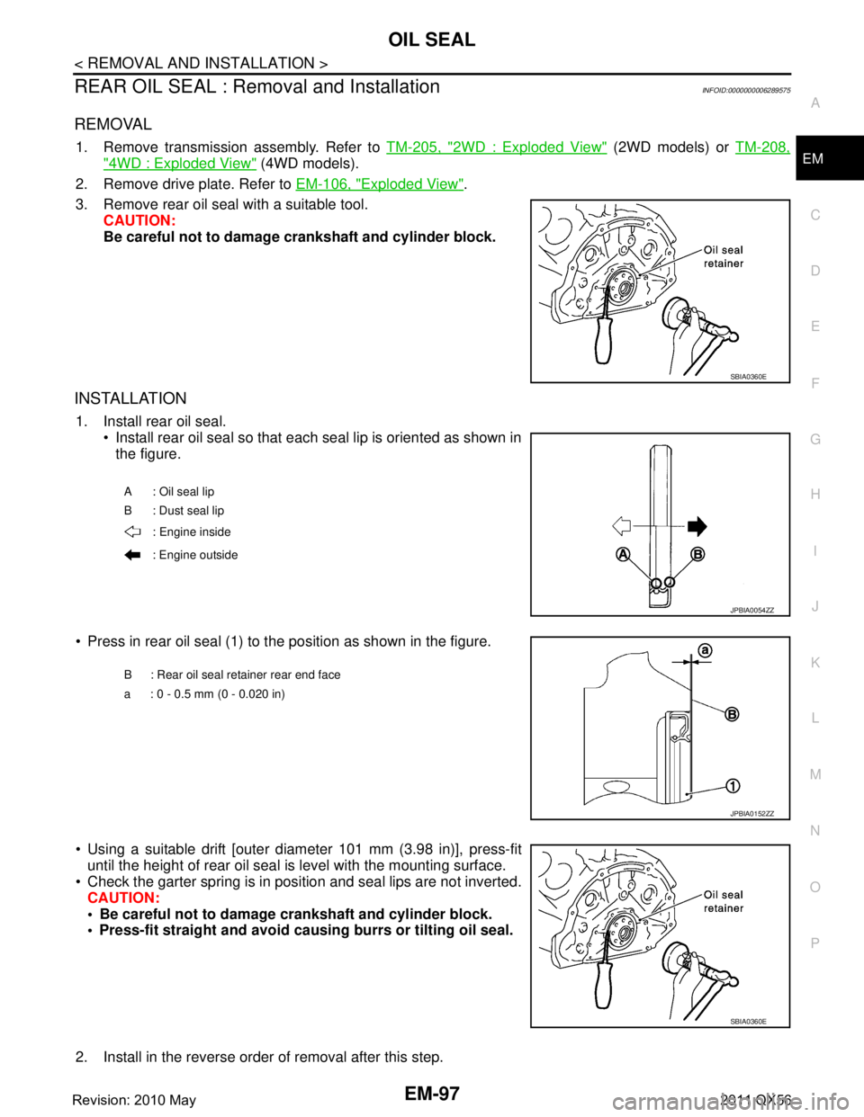
3. Remove rear oil seal with a suitable tool. CAUTION:
Be careful not to damage crankshaft and cylinder block.
INSTALLATION
1. Install rear oil seal. Install rear oil seal so that each seal lip is oriented as shown in
the figure.
Press in rear oil seal (1) to the position as shown in the figure.
Using a suitable drift [outer diameter 101 mm (3.98 in)], press-fit until the height of rear oil seal is level with the mounting surface.
Check the garter spring is in position and seal lips are not inverted. CAUTION:
Be careful not to damage crankshaft and cylinder block.
Press-fit straight and avoid cau sing burrs or tilting oil seal.
2. Install in the reverse order of removal after this step.
SBIA0360E
A : Oil seal lip
B : Dust seal lip : Engine inside
: Engine outside
JPBIA0054ZZ
B : Rear oil seal retainer rear end face
a : 0 - 0.5 mm (0 - 0.020 in)
JPBIA0152ZZ
SBIA0360E
Revision: 2010 May2011 QX56
Page 2685 of 5598
CYLINDER BLOCKEM-123
< UNIT DISASSEMBLY AND ASSEMBLY >
C
DE
F
G H
I
J
K L
M A
EM
NP
O
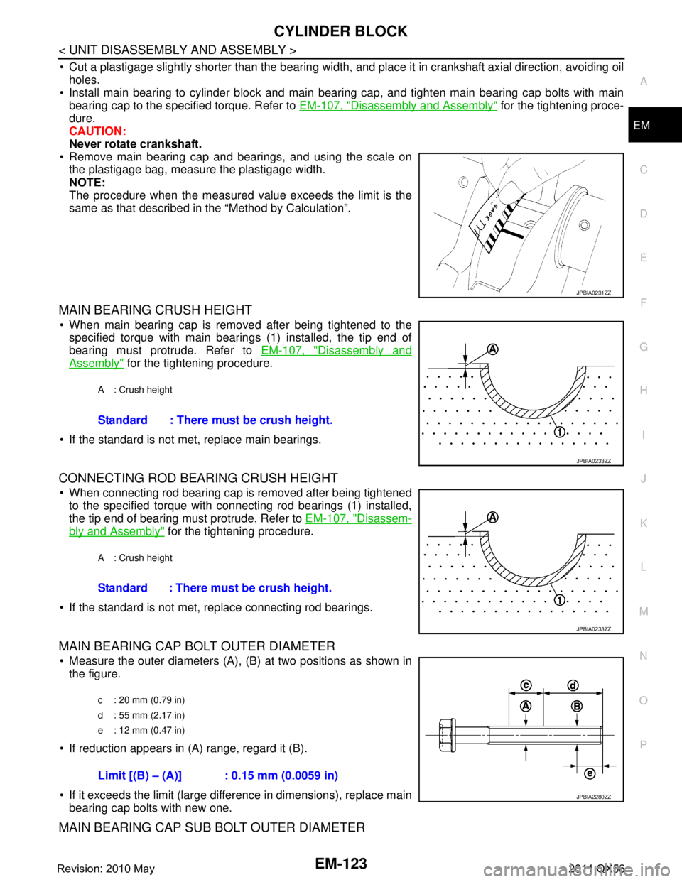
Cut a plastigage slightly shorter than the bearing width,
and place it in crankshaft axial direction, avoiding oil
holes.
Install main bearing to cylinder block and main bearing cap, and tighten main bearing cap bolts with main
bearing cap to the specified torque. Refer to EM-107, "
Disassembly and Assembly" for the tightening proce-
dure.
CAUTION:
Never rotate crankshaft.
Remove main bearing cap and bearings, and using the scale on the plastigage bag, measure the plastigage width.
NOTE:
The procedure when the measured value exceeds the limit is the
same as that described in the “Method by Calculation”.
MAIN BEARING CRUSH HEIGHT
When main bearing cap is removed after being tightened to thespecified torque with main bearings (1) installed, the tip end of
bearing must protrude. Refer to EM-107, "
Disassembly and
Assembly" for the tightening procedure.
If the standard is not met, replace main bearings.
CONNECTING ROD BEARING CRUSH HEIGHT
When connecting rod bearing cap is removed after being tightened to the specified torque with connecting rod bearings (1) installed,
the tip end of bearing must protrude. Refer to EM-107, "
Disassem-
bly and Assembly" for the tightening procedure.
If the standard is not met, replace connecting rod bearings.
MAIN BEARING CAP BOLT OUTER DIAMETER
Measure the outer diameters (A), (B) at two positions as shown in
the figure.
If reduction appears in (A) range, regard it (B).
If it exceeds the limit (large difference in dimensions), replace main bearing cap bolts with new one.
MAIN BEARING CAP SUB BOLT OUTER DIAMETER
JPBIA0231ZZ
A : Crush height
Standard : There must be crush height.
JPBIA0233ZZ
A : Crush height
Standard : There must be crush height.
JPBIA0233ZZ
c : 20 mm (0.79 in)
d : 55 mm (2.17 in)
e : 12 mm (0.47 in)
Limit [(B) – (A)] : 0.15 mm (0.0059 in)
JPBIA2280ZZ
Revision: 2010 May2011 QX56
Page 2695 of 5598
SERVICE DATA AND SPECIFICATIONS (SDS)
EM-133
< SERVICE DATA AND SPECIFICATIONS (SDS)
C
D E
F
G H
I
J
K L
M A
EM
NP
O
Exhaust ManifoldINFOID:0000000006289592
EXHAUST MANIFOLD
Unit: mm (in)
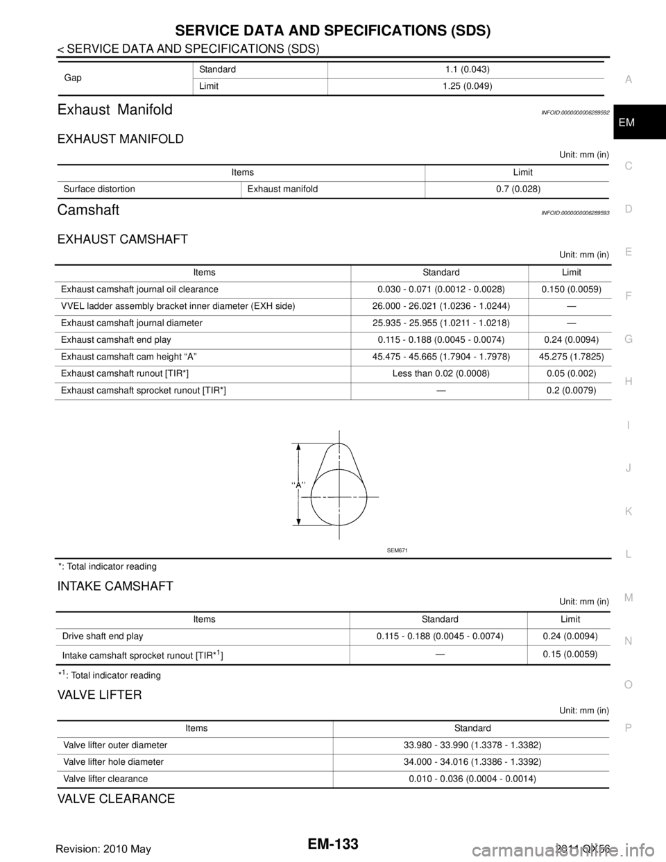
CamshaftINFOID:0000000006289593
EXHAUST CAMSHAFT
Unit: mm (in)
*: Total indicator reading
INTAKE CAMSHAFT
Unit: mm (in)
*1: Total indicator reading
VA LV E L I F T E R
Unit: mm (in)
VALVE CLEARANCE
Gap
Standard 1.1 (0.043)
Limit 1.25 (0.049)
Items Limit
Surface distortion Exhaust manifold 0.7 (0.028)
Items Standard Limit
Exhaust camshaft journal oil clearance 0.030 - 0.071 (0.0012 - 0.0028) 0.150 (0.0059)
VVEL ladder asse mbly bracket inner diameter (EXH side) 26.000 - 26.021 (1.0236 - 1.0244) —
Exhaust camshaft journal diameter 25.935 - 25.955 (1.0211 - 1.0218) —
Exhaust camshaft end play 0.115 - 0.188 (0.0045 - 0.0074) 0.24 (0.0094)
Exhaust camshaft cam height “A” 45.475 - 45.665 (1.7904 - 1.7978) 45.275 (1.7825)
Exhaust camshaft runout [TIR*] Less than 0.02 (0.0008) 0.05 (0.002)
Exhaust camshaft sprocket runout [TIR*] — 0.2 (0.0079)
SEM671
Items Standard Limit
Drive shaft end play 0.115 - 0.188 (0.0045 - 0.0074) 0.24 (0.0094)
Intake camshaft sprocket runout [TIR*
1] — 0.15 (0.0059)
Items Standard
Valve lifter outer diameter 33.980 - 33.990 (1.3378 - 1.3382)
Valve lifter hole diameter 34.000 - 34.016 (1.3386 - 1.3392)
Valve lifter clearance 0.010 - 0.036 (0.0004 - 0.0014)
Revision: 2010 May2011 QX56
Page 2697 of 5598
SERVICE DATA AND SPECIFICATIONS (SDS)
EM-135
< SERVICE DATA AND SPECIFICATIONS (SDS)
C
D E
F
G H
I
J
K L
M A
EM
NP
O
Cylinder HeadINFOID:0000000006289594
CYLINDER HEAD
Unit: mm (in)
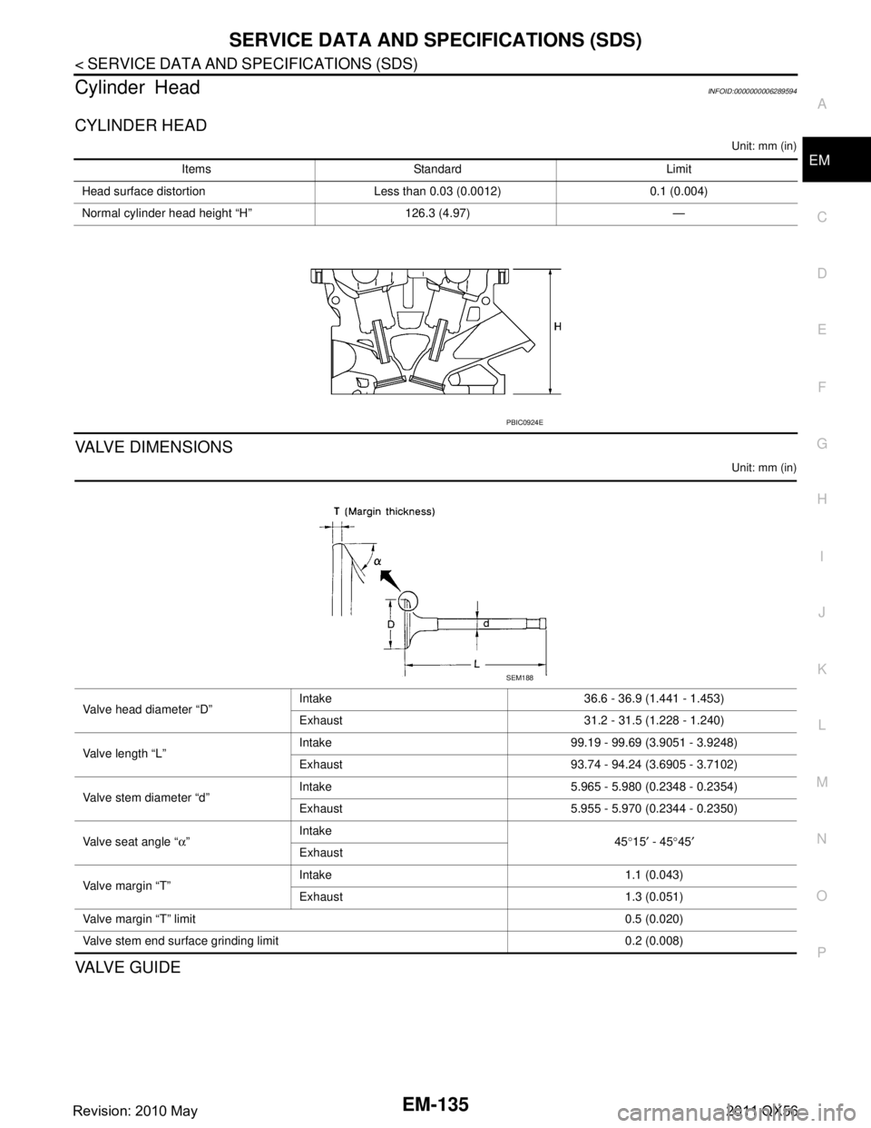
VALVE DIMENSIONS
Unit: mm (in)
VA LV E G U I D E
Items Standard Limit
Head surface distortion Less than 0.03 (0.0012) 0.1 (0.004)
Normal cylinder head height “H” 126.3 (4.97) —
PBIC0924E
Valve head diameter “D” Intake 36.6 - 36.9 (1.441 - 1.453)
Exhaust 31.2 - 31.5 (1.228 - 1.240)
Valve length “L” Intake 99.19 - 99.69 (3.9051 - 3.9248)
Exhaust 93.74 - 94.24 (3.6905 - 3.7102)
Valve stem diameter “d” Intake 5.965 - 5.980 (0.2348 - 0.2354)
Exhaust 5.955 - 5.970 (0.2344 - 0.2350)
Valve seat angle “ α” Intake
45°15 ′ - 45 °45 ′
Exhaust
Valve margin “T” Intake 1.1 (0.043)
Exhaust 1.3 (0.051)
Valve margin “T” limit 0.5 (0.020)
Valve stem end surface grinding limit 0.2 (0.008)
SEM188
Revision: 2010 May2011 QX56