2011 INFINITI QX56 Starter
[x] Cancel search: StarterPage 4740 of 5598
![INFINITI QX56 2011 Factory Service Manual
B210D STARTER RELAYSEC-133
< DTC/CIRCUIT DIAGNOSIS > [WITH INTELLIGENT KEY SYSTEM]
C
D
E
F
G H
I
J
L
M A
B
SEC
N
O P
B210D STARTER RELAY
DTC LogicINFOID:0000000006226296
DTC DETECTION LOGIC
NOTE:
If INFINITI QX56 2011 Factory Service Manual
B210D STARTER RELAYSEC-133
< DTC/CIRCUIT DIAGNOSIS > [WITH INTELLIGENT KEY SYSTEM]
C
D
E
F
G H
I
J
L
M A
B
SEC
N
O P
B210D STARTER RELAY
DTC LogicINFOID:0000000006226296
DTC DETECTION LOGIC
NOTE:
If](/manual-img/42/57033/w960_57033-4739.png)
B210D STARTER RELAYSEC-133
< DTC/CIRCUIT DIAGNOSIS > [WITH INTELLIGENT KEY SYSTEM]
C
D
E
F
G H
I
J
L
M A
B
SEC
N
O P
B210D STARTER RELAY
DTC LogicINFOID:0000000006226296
DTC DETECTION LOGIC
NOTE:
If DTC B210D is displayed with DTC U1000, first perform the trouble diagnosis for DTC U1000. Refer to PCS-
28, "DTC Logic".
DTC CONFIRMATION PROCEDURE
1.PERFORM DTC CONFIRMATION PROCEDURE
1. Press push-button ignition switch under the follo wing conditions to start engine, and wait 1 second or
more.
- Selector lever: In the P position
- Brake pedal: Depressed
2. Check DTC in “Self Diagnostic Result” mode of “IPDM E/R” using CONSULT-III.
Is DTC detected?
YES >> Go to SEC-133, "Diagnosis Procedure".
NO >> INSPECTION END
Diagnosis ProcedureINFOID:0000000006226297
1.INSPECTION START
1. Turn ignition switch ON.
2. Select “Self Diagnostic Result” mode of “IPDM E/R” using CONSULT-III.
3. Touch “ERASE”.
4. Perform DTC CONFIRMATION PROCEDURE for DTC B210D. Refer to SEC-133, "
DTC Logic".
Is DTC detected?
YES >> Replace IPDM E/R. Refer to PCS-32, "Removal and Installation".
NO >> INSPECTION END
DTC No. Trouble diagnosis name DTC detecting condition Possible cause
B210D STARTER RELAY ON When comparing the following items, IPDM E/R detects
that starter relay is stuck in the ON position for 1 second
or more.
Starter contro
l relay signal (CAN) from BCM
Starter relay status signal (CAN) from BCM
Starter control relay and starter relay status signal
(IPDM E/R input)
Starter control relay contro l signal (IPDM E/R output)
P/N position signal input Harness or connectors
(CAN communication
line is open or shorted.
IPDM E/R
Revision: 2010 May2011 QX56
Page 4741 of 5598
![INFINITI QX56 2011 Factory Service Manual
SEC-134
< DTC/CIRCUIT DIAGNOSIS >[WITH INTELLIGENT KEY SYSTEM]
B210E STARTER RELAY
B210E STARTER RELAY
DTC LogicINFOID:0000000006226298
DTC DETECTION LOGIC
NOTE:
If DTC B210E is displayed with DTC INFINITI QX56 2011 Factory Service Manual
SEC-134
< DTC/CIRCUIT DIAGNOSIS >[WITH INTELLIGENT KEY SYSTEM]
B210E STARTER RELAY
B210E STARTER RELAY
DTC LogicINFOID:0000000006226298
DTC DETECTION LOGIC
NOTE:
If DTC B210E is displayed with DTC](/manual-img/42/57033/w960_57033-4740.png)
SEC-134
< DTC/CIRCUIT DIAGNOSIS >[WITH INTELLIGENT KEY SYSTEM]
B210E STARTER RELAY
B210E STARTER RELAY
DTC LogicINFOID:0000000006226298
DTC DETECTION LOGIC
NOTE:
If DTC B210E is displayed with DTC U1000, first
perform the trouble diagnosis for DTC U1000. Refer to
PCS-28, "
DTC Logic".
If DTC B210E is displayed with DTC B2605, first perform the trouble diagnosis for DTC B2605. Refer to
SEC-91, "
DTC Logic".
When IPDM E/R power supply voltage is low (Approx. 7 - 8 V for about 1 second), the DTC B210E may be
detected.
DTC CONFIRMATION PROCEDURE
1.PERFORM DTC CONFIRMATION PROCEDURE
1. Press push-button ignition switch under the followi ng conditions to start engine, and wait 1 second or
more.
- Selector lever: In the P position
- Brake pedal: Depressed
2. Check DTC in “Self Diagnostic Result” mode of “IPDM E/R” using CONSULT-III.
Is DTC detected?
YES >> Go to SEC-134, "Diagnosis Procedure".
NO >> INSPECTION END
Diagnosis ProcedureINFOID:0000000006226299
1.CHECK STARTER RELAY OUTPUT SIGNAL
1. Check voltage between BCM harness connector and ground.
Is the inspection result normal?
YES >> GO TO 3.
NO >> GO TO 2.
2.CHECK STARTER RELAY OUTPUT SIGNAL CIRCUIT
1. Turn ignition switch OFF.
2. Disconnect BCM connector.
3. Disconnect IPDM E/R connector.
4. Check continuity between BCM harness connector and IPDM E/R harness connector.
DTC No. Trouble diagnosis name DTC detecting condition Possible cause
B210E STARTER RELAY OFF When comparing the following items, IPDM E/R
detects that starter relay is stuck in the OFF posi-
tion for 1 second or more.
Starter control relay
signal (CAN) from BCM
Starter relay status signal (CAN) from BCM
Starter control relay an d starter relay status
signal (IPDM E/R input)
Starter control relay co ntrol signal (IPDM E/R
output)
P/N position signal input Harness or connector
(CAN communication line is open or
shorted.)
Harness or connector (Starter relay circuit is open or
shorted.)
IPDM E/R
BCM
Battery
(+)
(–) Condition
Voltage (V)
(Approx.)
BCM
Connector Terminal Ignition switch Brake pedal Selector lever
M71 97 Ground ON Depressed P or N 12
Other than above 0
Revision: 2010 May2011 QX56
Page 4742 of 5598
![INFINITI QX56 2011 Factory Service Manual
B210E STARTER RELAYSEC-135
< DTC/CIRCUIT DIAGNOSIS > [WITH INTELLIGENT KEY SYSTEM]
C
D
E
F
G H
I
J
L
M A
B
SEC
N
O P
5. Check continuity between BCM harness connector and ground.
Is the inspection re INFINITI QX56 2011 Factory Service Manual
B210E STARTER RELAYSEC-135
< DTC/CIRCUIT DIAGNOSIS > [WITH INTELLIGENT KEY SYSTEM]
C
D
E
F
G H
I
J
L
M A
B
SEC
N
O P
5. Check continuity between BCM harness connector and ground.
Is the inspection re](/manual-img/42/57033/w960_57033-4741.png)
B210E STARTER RELAYSEC-135
< DTC/CIRCUIT DIAGNOSIS > [WITH INTELLIGENT KEY SYSTEM]
C
D
E
F
G H
I
J
L
M A
B
SEC
N
O P
5. Check continuity between BCM harness connector and ground.
Is the inspection result normal?
YES >> Replace IPDM E/R. Refer to PCS-32, "Removal and Installation".
NO >> Repair or replace harness.
3.CHECK STARTER RELAY CIRCUIT
1. Turn ignition switch OFF.
2. Disconnect IPDM E/R connector.
3. Check voltage between IPDM E/R harness connector and ground.
Is the inspection result normal?
YES >> GO TO 4.
NO >> Check harness for open or short bet ween IPDM E/R and battery. Refer to STR-7, "
Wiring Dia-
gram".
4.REPLACE BCM
1. Replace BCM. Refer to BCS-81, "
Removal and Installation".
2. Perform DTC CONFIRMATION PROCEDIURE for DTC B210E. Refer to SEC-134, "
DTC Logic".
Is the inspection result normal?
YES >> INSPECTION END
NO >> Replace IPDM E/R. Refer to PCS-32, "
Removal and Installation".
BCM IPDM E/R
Continuity
Connector Terminal Connector Terminal
M71 97 E13 30 Existed
BCM GroundContinuity
Connector Terminal
M71 97 Not existed
(+) (–)Voltage (V)
(Approx.)
IPDM E/R
Connector Terminal E10 4 Ground Battery voltage
Revision: 2010 May2011 QX56
Page 5069 of 5598
STR-1
ENGINE
C
DE
F
G H
I
J
K L
M
SECTION STR
A
STR
N
O P
CONTENTS
STARTING SYSTEM
PRECAUTION ................ ...............................2
PRECAUTIONS .............................................. .....2
Precaution for Supplemental Restraint System
(SRS) "AIR BAG" and "SEAT BELT PRE-TEN-
SIONER" ............................................................. ......
2
Precaution Necessary for Steering Wheel Rota-
tion after Battery Disconnect .....................................
2
PREPARATION ............................................4
PREPARATION .............................................. .....4
Special Service Tools .......................................... ......4
Commercial Service Tools ........................................4
SYSTEM DESCRIPTION ..............................5
COMPONENT PARTS ................................... .....5
Component Parts Location .................................. ......5
Component Description ............................................5
SYSTEM ..............................................................6
System Diagram .................................................. ......6
System Description ...................................................6
WIRING DIAGRAM .......................................7
STARTING SYSTEM ...................................... .....7
Wiring Diagram ................................................... ......7
BASIC INSPECTION ...................................11
DIAGNOSIS AND REPAIR WORKFLOW ........11
Work Flow ............................................................ ....11
DTC/CIRCUIT DIAGNOSIS .........................14
B TERMINAL CIRCUIT .....................................14
Diagnosis Procedure ........................................... ....14
S CONNECTOR CIRCUIT .................................15
Diagnosis Procedure ...............................................15
SYMPTOM DIAGNOSIS ..............................16
STARTING SYSTEM .........................................16
Symptom Table ................................................... ....16
REMOVAL AND INSTALLATION ...............17
STARTER MOTOR ...........................................17
Exploded View ..................................................... ....17
Removal and Installation .........................................18
Inspection ................................................................18
SERVICE DATA AND SPECIFICATIONS
(SDS) ............... .............................................
20
SERVICE DATA AND SPECIFICATIONS
(SDS) .................................................................
20
Starter Motor .......................................................
Revision: 2010 May2011 QX56
Page 5073 of 5598
COMPONENT PARTSSTR-5
< SYSTEM DESCRIPTION >
C
DE
F
G H
I
J
K L
M A
STR
NP
O
SYSTEM DESCRIPTION
COMPONENT PARTS
Component Parts LocationINFOID:0000000006275518
Component DescriptionINFOID:0000000006275519
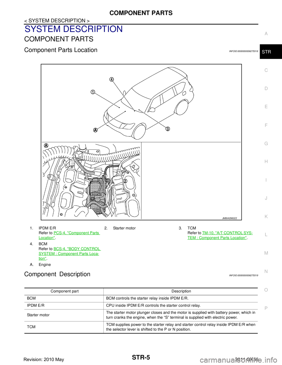
1. IPDM E/R
Refer to PCS-4, "
Component Parts
Location". 2. Starter motor 3. TCM
Refer to TM-10, "
A/T CONTROL SYS-
TEM : Component Parts Location".
4. BCM Refer to BCS-4, "
BODY CONTROL
SYSTEM : Componen t Parts Loca-
tion".
A. Engine
JMBIA2982ZZ
Component part Description
BCM BCM controls the starter relay inside IPDM E/R.
IPDM E/R CPU inside IPDM E/R controls the starter control relay.
Starter motor The starter motor plunger closes and the motor is supplied with battery power, which in
turn cranks the engine, when the “S” terminal is supplied with electric power.
TCM TCM supplies power to the starter relay and starter control relay inside IPDM E/R when
the selector lever is shifted to the P or N position.
Revision: 2010 May2011 QX56
Page 5074 of 5598
STR-6
< SYSTEM DESCRIPTION >
SYSTEM
SYSTEM
System DiagramINFOID:0000000006275520
System DescriptionINFOID:0000000006275521
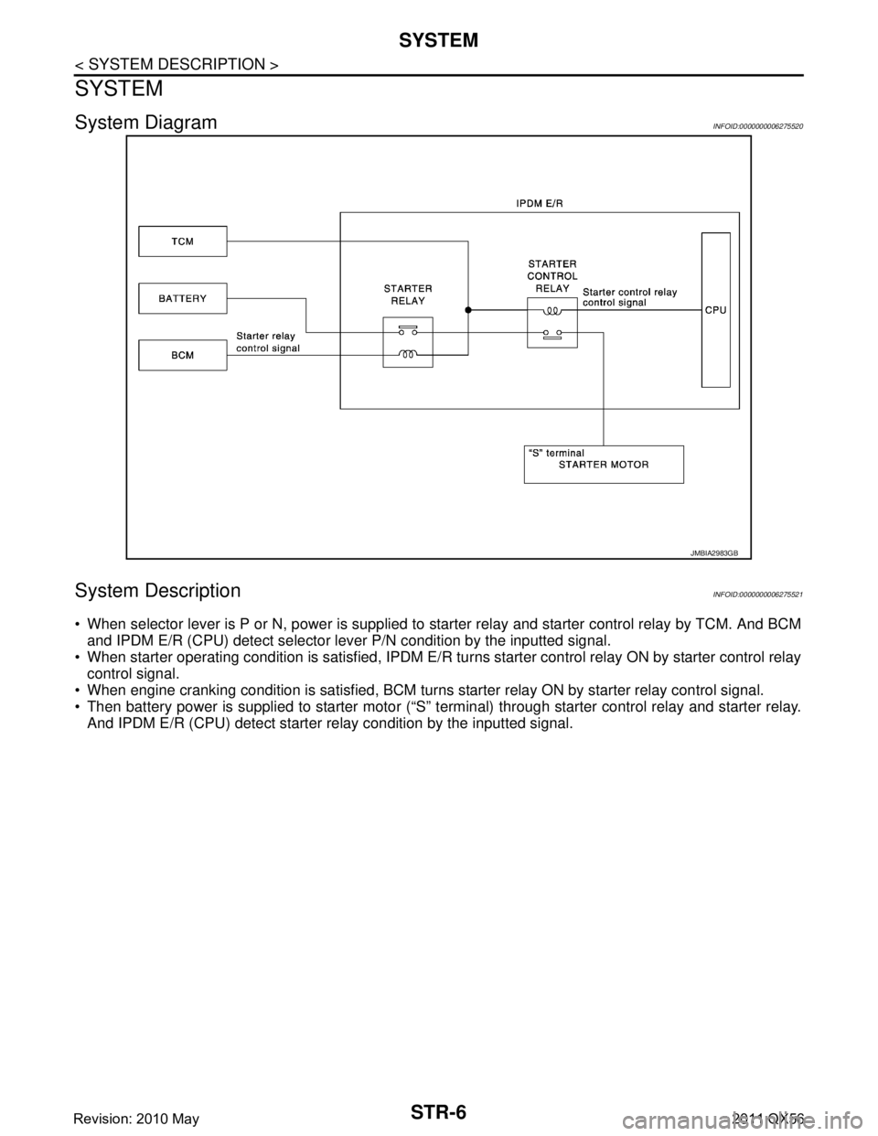
When selector lever is P or N, power is supplied to starter relay and starter control relay by TCM. And BCM
and IPDM E/R (CPU) detect selector lever P/N condition by the inputted signal.
When starter operating condition is satisfied, IPDM E/R tu rns starter control relay ON by starter control relay
control signal.
When engine cranking condition is satisfied, BCM turns starter relay ON by starter relay control signal.
Then battery power is supplied to starter motor (“S” terminal) through starter control relay and starter relay. And IPDM E/R (CPU) detect starter re lay condition by the inputted signal.
JMBIA2983GB
Revision: 2010 May2011 QX56
Page 5080 of 5598
STR-12
< BASIC INSPECTION >
DIAGNOSIS AND REPAIR WORKFLOW
NOTE:
To ensure a complete and thorough diagnosis, the battery, starter motor and alternator test segments must be
done as a set from start to finish.
1.DIAGNOSIS WITH STARTING /CHARGING SYSTEM TESTER
Perform the starting system test with Starting/Char ging System Tester (SST: J-44373). For details and operat-
ing instructions, refer to Technical Service Bulletin.
Te s t r e s u l t
CRANKING VOLTAGE NORMAL>>GO TO 2.
CRANKING VOLTAGE LOW>>GO TO 5.
CHARGE BATTERY>>Perform the slow battery charging procedure. (Initial rate of charge is 10A for 12
hours.) Perform battery test again. Re fer to Technical Service Bulletin.
REPLACE BATTERY>>Before replacing battery, clean t he battery cable clamps and battery posts. Perform
battery test again. Refer to Technical Service Bu lletin. If second test result is “REPLACE BAT-
TERY”, then do so. Perform battery test again to confirm repair.
2.CRANKING CHECK
Check that the starter motor operates correctly.
Does the engine crank normally?
YES >> GO TO 3.
NO >> GO TO 4.
3.ENGINE START CHECK
Check that the engine starts.
Does the engine start?
YES >> Starter motor is OK. INSPECTION END
NO >> Perform further diagnosis of engine mechanical or engine control system. Refer EM and EC sec-
tions. Once resolved, perform battery test again.
4.STARTER MOTOR ACTIVATION
Check that the starter motor operates.
Does the starter motor turn?
YES >> Check ring gear and starter motor drive pinion. Once resolved, perform battery test again.
NO >> GO TO 7.
5.COMPARISON BETWEEN ENGINE COOLANT AND CRANKING VOLTAGE
Compare the engine coolant temperature and the cranking voltage with the specifications.
Minimum Specification of Cranking Voltage Referencing Coolant Temperature
Is the voltage less than the specified value?
YES >> GO TO 7.
NO >> GO TO 6.
6.STARTER OPERATION
Check the starter operation status.
Does the starter motor turn smoothly?
YES >> Starter motor is OK. INSPECTION END
NO >> GO TO 7.
7.“B” TERMINAL CIRCUIT INSPECTION
Check “B” terminal circuit. Refer to STR-14, "
Diagnosis Procedure".
Is
“B” terminal circuit normal?
Engine coolant temperature [ °C ( °F)] Voltage [V]
− 30 to −20 ( −22 to −4) 8.6
− 19 to −10 ( −2 to 14) 9.1
− 9 to 0 (16 to 32) 9.5
More than 1 (More than 34) 9.9
Revision: 2010 May2011 QX56
Page 5081 of 5598
DIAGNOSIS AND REPAIR WORKFLOWSTR-13
< BASIC INSPECTION >
C
DE
F
G H
I
J
K L
M A
STR
NP
O
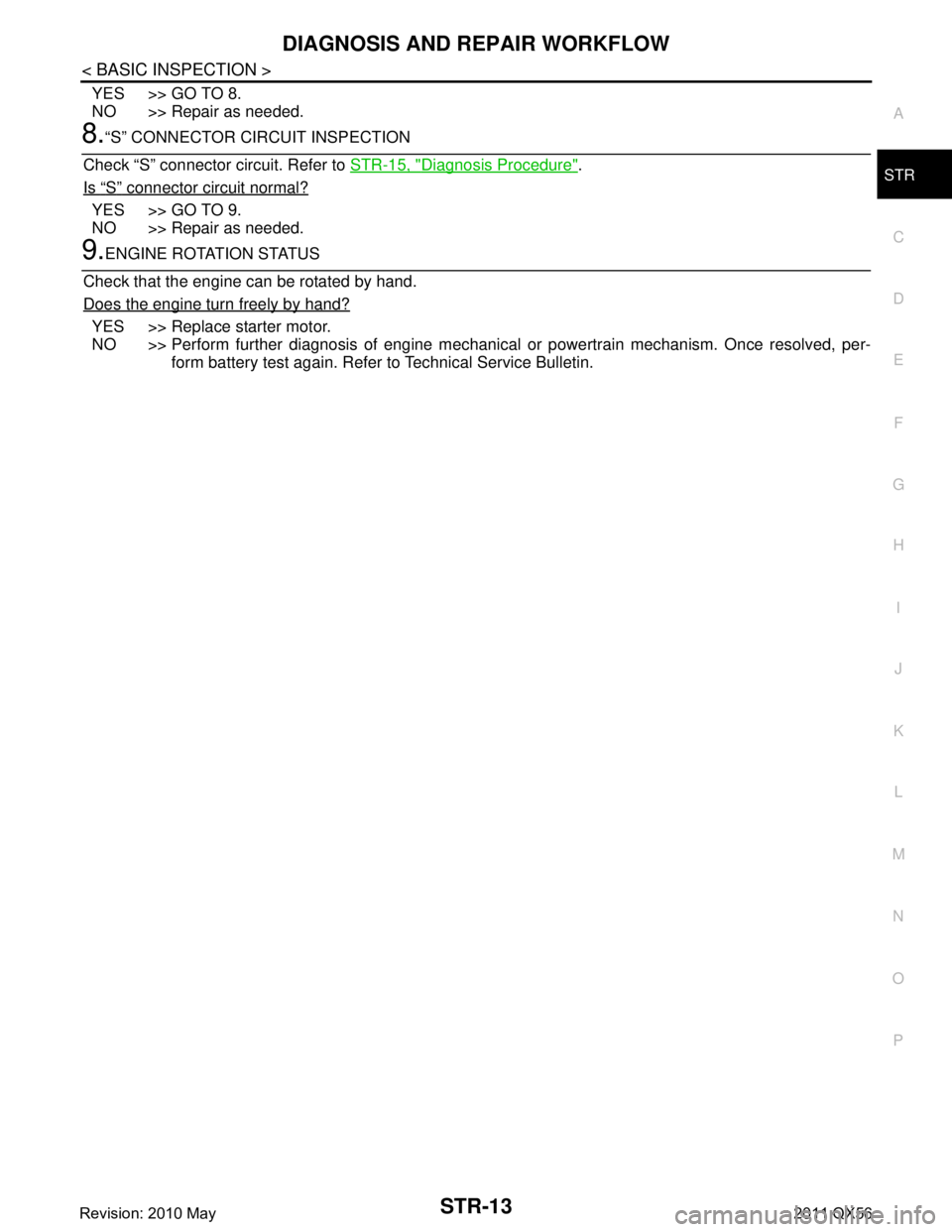
YES >> GO TO 8.
NO >> Repair as needed.
8.“S” CONNECTOR CIRCUIT INSPECTION
Check “S” connector circuit. Refer to STR-15, "
Diagnosis Procedure".
Is
“S” connector circuit normal?
YES >> GO TO 9.
NO >> Repair as needed.
9.ENGINE ROTATION STATUS
Check that the engine can be rotated by hand.
Does the engine turn freely by hand?
YES >> Replace starter motor.
NO >> Perform further diagnosis of engine mechanical or powertrain mechanism. Once resolved, per-
form battery test again. Refer to Technical Service Bulletin.
Revision: 2010 May2011 QX56