2011 INFINITI QX56 Camshaft sensor
[x] Cancel search: Camshaft sensorPage 2502 of 5598
![INFINITI QX56 2011 Factory Service Manual
EC-478
< DTC/CIRCUIT DIAGNOSIS >[VK56VD]
P2138 APP SENSOR
P2138 APP SENSOR
DTC LogicINFOID:0000000006217981
DTC DETECTION LOGIC
NOTE:
If DTC P2138 is displayed with DTC P0643, first pe
rform the trou INFINITI QX56 2011 Factory Service Manual
EC-478
< DTC/CIRCUIT DIAGNOSIS >[VK56VD]
P2138 APP SENSOR
P2138 APP SENSOR
DTC LogicINFOID:0000000006217981
DTC DETECTION LOGIC
NOTE:
If DTC P2138 is displayed with DTC P0643, first pe
rform the trou](/manual-img/42/57033/w960_57033-2501.png)
EC-478
< DTC/CIRCUIT DIAGNOSIS >[VK56VD]
P2138 APP SENSOR
P2138 APP SENSOR
DTC LogicINFOID:0000000006217981
DTC DETECTION LOGIC
NOTE:
If DTC P2138 is displayed with DTC P0643, first pe
rform the trouble diagnosis for DTC P0643. Refer to
EC-381, "
DTC Logic".
DTC CONFIRMATION PROCEDURE
1.PRECONDITIONING
1. Turn ignition switch OFF and wait at least 10 seconds.
2. Turn ignition switch ON.
3. Turn ignition switch OFF and wait at least 10 seconds.
TESTING CONDITION:
Before performing the following procedure, confi rm that battery voltage is 8 V or more at idle.
>> GO TO 2.
2.PERFORM DTC CONFIRMATION PROCEDURE
1. Start engine and let it idle for 1 second.
2. Check DTC.
Is DTC detected?
YES >> Go to EC-478, "Diagnosis Procedure".
NO >> INSPECTION END
Diagnosis ProcedureINFOID:0000000006217982
1.CHECK ACCELERATOR PEDAL POSITION SENSOR 1 POWER SUPPLY CIRCUIT
1. Disconnect accelerator pedal position (APP) sensor harness connector.
2. Turn ignition switch ON.
3. Check the voltage between APP sensor harness connector and ground.
Is the inspection result normal?
DTC No. Trouble diagnosis name
(Trouble diagnosis content) DTC detecting condition Possible cause
P2138 APP SENSOR
(Accelerator pedal position
sensor circuit range/perfor-
mance) Rationally incorrect voltage is
sent to ECM compared with
the signals from APP sensor 1
and APP sensor 2. Harness or connectors
(APP sensor 1 or 2 circuit is open or shorted.)
[CKP sensor circuit is shorted.]
[CMP sensor (bank 1) circuit is shorted.]
(Battery current sensor circuit is shorted.)
(Refrigerant pressure sensor circuit is shorted.)
(EVAP control system pressure sensor circuit is short-
ed.)
Accelerator pedal position sensor (APP sensor 1 or 2)
Crankshaft position sensor
Camshaft position sensor (bank 1)
Refrigerant pressure sensor
Battery current sensor
EVAP control system pressure sensor
APP sensor Ground Voltage (V)
Connector Terminal
E110
(Without ICC) 2
Ground Approx. 5
E67
(With ICC) 12
Revision: 2010 May2011 QX56
Page 2503 of 5598
![INFINITI QX56 2011 Factory Service Manual
P2138 APP SENSOREC-479
< DTC/CIRCUIT DIAGNOSIS > [VK56VD]
C
D
E
F
G H
I
J
K L
M A
EC
NP
O
YES >> GO TO 3.
NO >> GO TO 2.
2.DETECT MALFUNCTIONING PART
Check the following.
Loose or poor connection f INFINITI QX56 2011 Factory Service Manual
P2138 APP SENSOREC-479
< DTC/CIRCUIT DIAGNOSIS > [VK56VD]
C
D
E
F
G H
I
J
K L
M A
EC
NP
O
YES >> GO TO 3.
NO >> GO TO 2.
2.DETECT MALFUNCTIONING PART
Check the following.
Loose or poor connection f](/manual-img/42/57033/w960_57033-2502.png)
P2138 APP SENSOREC-479
< DTC/CIRCUIT DIAGNOSIS > [VK56VD]
C
D
E
F
G H
I
J
K L
M A
EC
NP
O
YES >> GO TO 3.
NO >> GO TO 2.
2.DETECT MALFUNCTIONING PART
Check the following.
Loose or poor connection for each connector and harness
Harness for open or short between ECM and APP sensor
>> Repair open circuit, short to ground or short to power in harness or connectors.
3.CHECK APP SENSOR 2 POWER SUPPLY CIRCUIT-I
1. Turn ignition switch ON.
2. Check the voltage between APP sensor harness connector and ground.
Is the inspection result normal?
YES >> GO TO 8.
NO >> GO TO 4.
4.CHECK APP SENSOR 2 POWER SUPPLY CIRCUIT-II
1. Turn ignition switch OFF.
2. Disconnect ECM harness connector.
3. Check the continuity between APP sens or harness connector and ECM harness connector.
Is the inspection result normal?
YES >> GO TO 6.
NO >> GO TO 5.
5.DETECT MALFUNCTIONING PART
Check the following.
Harness for open or short between ECM and accelerator pedal position sensor
Loose or poor connection for each connector and harness
>> Repair open circuit.
6.CHECK SENSOR POWER SUPPLY CIRCUIT
Check harness for short to power and short to ground, between the following terminals.
APP sensor
Ground Voltage (V)
Connector Terminal
E110
(Without ICC) 1
Ground Approx. 5
E67
(With ICC) 9
APP sensor ECM
Continuity
Connector Terminal Connector Terminal
E110
(Without ICC) 1
E80 131 Existed
E67
(With ICC) 9
ECM Sensor
Connector Terminal Name Connector Terminal
F110 76 Crankshaft position sensor F74 1
77 Camshaft position sensor (bank 1) F84 1
Revision: 2010 May2011 QX56
Page 2504 of 5598
![INFINITI QX56 2011 Factory Service Manual
EC-480
< DTC/CIRCUIT DIAGNOSIS >[VK56VD]
P2138 APP SENSOR
Is the inspection result normal?
YES >> GO TO 7.
NO >> Repair short to ground or short to power in harness or connectors.
7.CHECK COMPONENTS
INFINITI QX56 2011 Factory Service Manual
EC-480
< DTC/CIRCUIT DIAGNOSIS >[VK56VD]
P2138 APP SENSOR
Is the inspection result normal?
YES >> GO TO 7.
NO >> Repair short to ground or short to power in harness or connectors.
7.CHECK COMPONENTS](/manual-img/42/57033/w960_57033-2503.png)
EC-480
< DTC/CIRCUIT DIAGNOSIS >[VK56VD]
P2138 APP SENSOR
Is the inspection result normal?
YES >> GO TO 7.
NO >> Repair short to ground or short to power in harness or connectors.
7.CHECK COMPONENTS
Check the following.
Crankshaft position sensor (Refer to EC-301, "
Component Inspection (Crankshaft Position Sensor)".)
Camshaft position sensor (bank 1) (Refer to EC-306, "
Component Inspection (Camshaft Position Sensor)".)
Refrigerant pressure sensor (Refer to EC-520, "
Component Function Check".)
EVAP control system pressure sensor (Refer to EC-335, "
Component Inspection (EVAP Control System
Pressure Sensor)".)
Is the inspection result normal?
YES >> GO TO 14.
NO >> Replace malfunctioning component.
8.CHECK APP SENSOR GROUND CIRCUIT FOR OPEN AND SHORT
1. Turn ignition switch OFF.
2. Disconnect ECM harness connector.
3. Check the continuity between APP sens or harness connector and ECM harness connector.
4. Also check harness for short to ground and short to power.
Is the inspection result normal?
YES >> GO TO 10.
NO >> GO TO 9.
9.DETECT MALFUNCTIONING PART
Check the following.
Harness for open or short between ECM and accelerator pedal position sensor
Loose or poor connection for each connector and harness
>> Repair open circuit, short to ground or short to power in harness or connectors.
10.CHECK APP SENSOR INPUT SIGNAL CIRCUIT FOR OPEN AND SHORT
1. Check the continuity between APP sens or harness connector and ECM harness connector.
E80133Battery current sensor E63 2
Refrigerant pressure sensor E77 1
EVAP control system pressure sen-
sor
C17 3
131 APP sensor (Without ICC) E110 1
APP sensor (with ICC) E67 9
ECM Sensor
Connector Terminal Name Connector Terminal
APP sensor ECM Continuity
Connector Terminal Connector Terminal
E110
(Without ICC) 4
E80 140
Existed
5129
E67
(With ICC) 11
E80 140
Existed
8129
Revision: 2010 May2011 QX56
Page 2549 of 5598
![INFINITI QX56 2011 Factory Service Manual
ENGINE CONTROL SYSTEM SYMPTOMSEC-525
< SYMPTOM DIAGNOSIS > [VK56VD]
C
D
E
F
G H
I
J
K L
M A
EC
NP
O
Mass air flow sensor circuit
1
12 2
222 2 EC-201
Engine coolant temperature sensor circuit
333
EC-2 INFINITI QX56 2011 Factory Service Manual
ENGINE CONTROL SYSTEM SYMPTOMSEC-525
< SYMPTOM DIAGNOSIS > [VK56VD]
C
D
E
F
G H
I
J
K L
M A
EC
NP
O
Mass air flow sensor circuit
1
12 2
222 2 EC-201
Engine coolant temperature sensor circuit
333
EC-2](/manual-img/42/57033/w960_57033-2548.png)
ENGINE CONTROL SYSTEM SYMPTOMSEC-525
< SYMPTOM DIAGNOSIS > [VK56VD]
C
D
E
F
G H
I
J
K L
M A
EC
NP
O
Mass air flow sensor circuit
1
12 2
222 2 EC-201
Engine coolant temperature sensor circuit
333
EC-217
Air fuel ratio (A/F) sensor 1 circuit EC-181
EC-228
EC-232
EC-235
EC-238
Throttle position sensor circuit
22EC-219
EC-288
EC-406
EC-407
EC-475
Accelerator pedal position sensor circuit 3 2 1
EC-468EC-471
EC-478
Knock sensor circuit 2 3
EC-297
Engine oil temperature sensor 4 2 3EC-285
Crankshaft position sensor circuit 2 2EC-299
Camshaft position sensor circuit 3 2EC-303
Vehicle speed signal circuit 2 3 3 3EC-356
Power steering pressure sensor circuit 2 3 3EC-371
ECM 22333333333EC-376EC-378
EC-380
Intake valve timing control solenoid valve cir-
cuit
32 13223 3
EC-193
VVEL control module 3 4 4 3 EC-451EC-452
VVEL actuator motor 3 4 4 3
EC-390
VVEL actuator motor relay 3 4 4 3EC-393
VVEL control shaft position sensor 3 4 4 3EC-387
PNP signal circuit 3 3 3 3 3EC-383
Refrigerant pressure sensor circuit 2 3 3 4EC-520
Electrical load signal circuit 3EC-493
Air conditioner circuit 223333333 3 2HAC-60
ABS actuator and electric unit (control unit) 4BRC-60
SYMPTOM
Reference
page
HARD/NO START/RESTART (EXCP. HA)
ENGINE STALL
HESITATION/SURGING/FLAT SPOT
SPARK KNOCK/DETONATION
LACK OF POWER/POOR ACCELERATION
HIGH IDLE/LOW IDLE
ROUGH IDLE/HUNTING
IDLING VIBRATION
SLOW/NO RETURN TO IDLE
OVERHEATS/WATER TEMPERATURE HIGH
EXCESSIVE FUEL CONSUMPTION
EXCESSIVE OIL CONSUMPTION
BATTERY DEAD (UNDER CHARGE)
Warranty symptom code AA AB AC AD AE AF AG AH AJ AK AL AM HA
Revision: 2010 May2011 QX56
Page 2551 of 5598
![INFINITI QX56 2011 Factory Service Manual
ENGINE CONTROL SYSTEM SYMPTOMSEC-527
< SYMPTOM DIAGNOSIS > [VK56VD]
C
D
E
F
G H
I
J
K L
M A
EC
NP
O
Air Air duct
55555 5 EM-28
Air cleaner
EM-27
Air leakage from air duct
(Mass air flow sensor — el INFINITI QX56 2011 Factory Service Manual
ENGINE CONTROL SYSTEM SYMPTOMSEC-527
< SYMPTOM DIAGNOSIS > [VK56VD]
C
D
E
F
G H
I
J
K L
M A
EC
NP
O
Air Air duct
55555 5 EM-28
Air cleaner
EM-27
Air leakage from air duct
(Mass air flow sensor — el](/manual-img/42/57033/w960_57033-2550.png)
ENGINE CONTROL SYSTEM SYMPTOMSEC-527
< SYMPTOM DIAGNOSIS > [VK56VD]
C
D
E
F
G H
I
J
K L
M A
EC
NP
O
Air Air duct
55555 5 EM-28
Air cleaner
EM-27
Air leakage from air duct
(Mass air flow sensor — electric
throttle control actuator)
5555 EM-28
Electric throttle control actuator
EC-460
Air leakage from intake manifold/
Collector/GasketEM-30
Cranking Battery
111111
11
PG-161
Generator circuit
CHG-13
Starter circuit 3STR-11
Signal plate 6EM-106
PNP signal 4EC-383
Engine Cylinder head
55555 55 5 EM-92
Cylinder head gasket 4 3
Cylinder block
66666 66 6 4
EM-115
Piston
Piston ring
Connecting rod
Bearing
Crankshaft
Va l v e
mecha-
nism Timing chain
55555 55 5 EM-72
Camshaft
EM-77
Intake valve timing controlEM-61
Intake valve
3EM-92
Exhaust valve
Exhaust Exhaust manifold/Tube/Muffler/ Gasket 55555 55 5 EM-42
EX-6Three way catalystSYMPTOM
Reference
page
HARD/NO START/RESTART (EXCP. HA)
ENGINE STALL
HESITATION/SURGING/FLAT SPOT
SPARK KNOCK/DETONATION
LACK OF POWER/POOR ACCELERATION
HIGH IDLE/LOW IDLE
ROUGH IDLE/HUNTING
IDLING VIBRATION
SLOW/NO RETURN TO IDLE
OVERHEATS/WATER TEMPERATURE HIGH
EXCESSIVE FUEL CONSUMPTION
EXCESSIVE OIL CONSUMPTION
BATTERY DEAD (UNDER CHARGE)
Warranty symptom code AA AB AC AD AE AF AG AH AJ AK AL AM HA
Revision: 2010 May2011 QX56
Page 2598 of 5598

EM-36
< REMOVAL AND INSTALLATION >
VVEL ACTUATOR ASSEMBLY
VVEL ACTUATOR ASSEMBLY
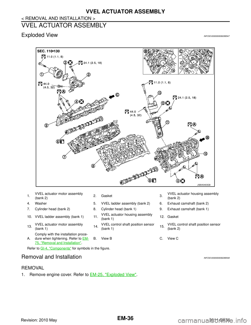
Exploded ViewINFOID:0000000006289547
Removal and InstallationINFOID:0000000006289548
REMOVAL
1. Remove engine cover. Refer to EM-25, "Exploded View".
1.VVEL actuator motor assembly
(bank 2) 2. Gasket 3.
VVEL actuator ho
using assembly
(bank 2)
4. Washer 5. VVEL ladder as sembly (bank 2) 6. Exhaust camshaft (bank 2)
7. Cylinder head (bank 2) 8. Cylinder head (bank 1) 9. Exhaust camshaft (bank 1)
10. VVEL ladder assembly (bank 1) 11. VVEL actuator housing assembly
(bank 1)12. Gasket
13. VVEL actuator motor assembly
(bank 1) 14.
VVEL control shaft
position sensor
(bank 1) 15.
VVEL control shaft
position sensor
(bank 2)
A. Comply with the installation proce-
dure when tightening. Refer to
EM-
75, "Removal and Installation".B. View B C. View C
Refer to GI-4, "
Components" for symbols in the figure.
JSBIA0403GB
Revision: 2010 May2011 QX56
Page 2624 of 5598

EM-62
< REMOVAL AND INSTALLATION >
TIMING CHAIN
Removal and Installation
INFOID:0000000006289566
REMOVAL
1. Release fuel pressure. Refer to EC-153, "Work Procedure".
2. Drain engine coolant from radiator. Refer to CO-8, "
Draining".
3. Remove fan shroud (lower). Refer to CO-13, "
Exploded View".
4. Remove fan bracket. Refer to CO-16, "
Exploded View".
5. Remove drive belt auto-tensioner. Refer to EM-26, "
Exploded View".
6. Remove oil level gauge and oil level gauge guide. Refer to EM-57, "
Exploded View".
7. Move power steering oil pump to the posit ion without the hindrance for work. Refer to ST-48, "
Exploded
View".
8. Remove alternator, alternator bracket and alternator stay. Refer to CHG-25, "
Exploded View".
9. Move power steering reservoir tank to the position without the hindrance for work, and then remove Res- ervoir tank bracket. Refer to ST-54, "
Exploded View".
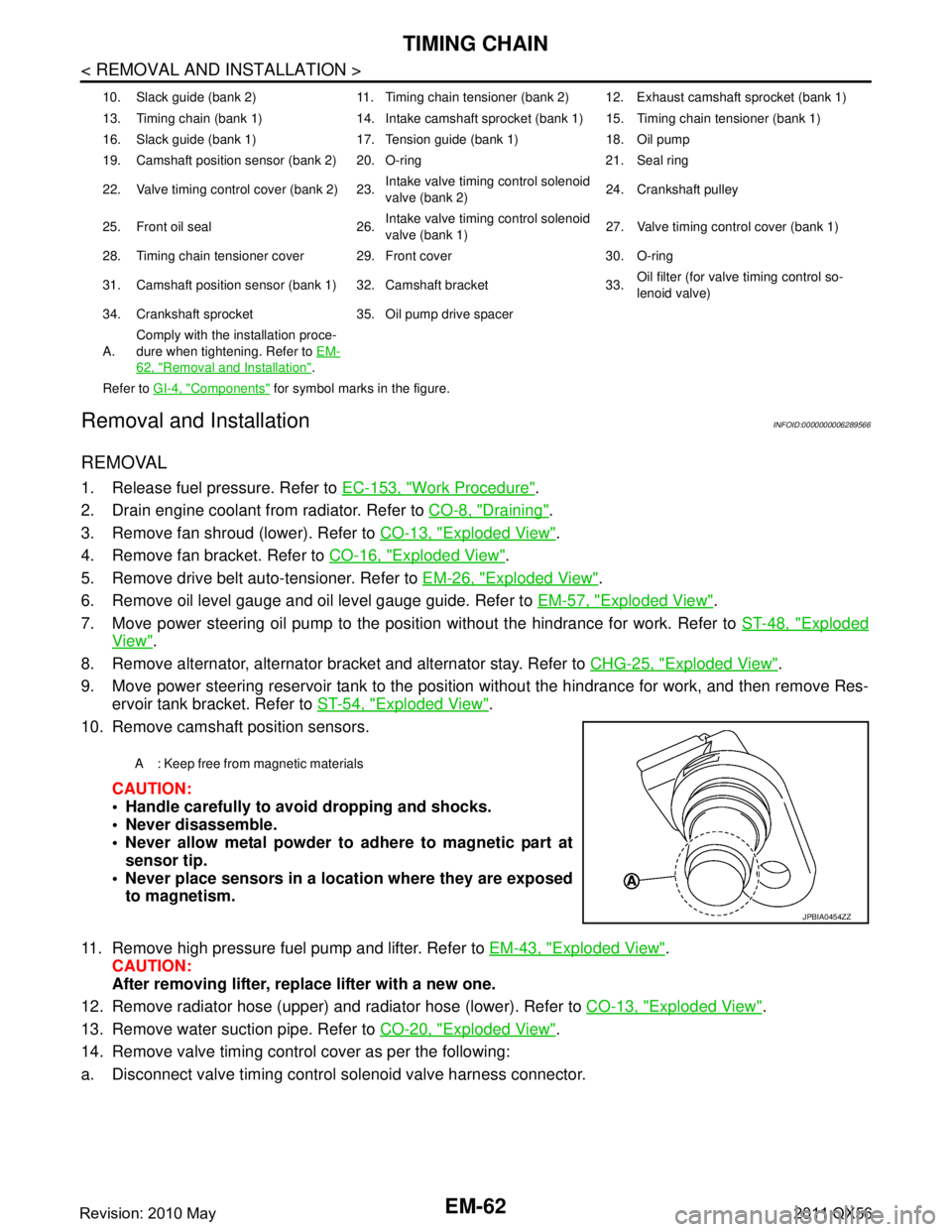
10. Remove camshaft position sensors.
CAUTION:
Handle carefully to avoid dropping and shocks.
Never disassemble.
Never allow metal powder to adhere to magnetic part atsensor tip.
Never place sensors in a lo cation where they are exposed
to magnetism.
11. Remove high pressure fuel pump and lifter. Refer to EM-43, "
Exploded View".
CAUTION:
After removing lifter, replace lifter with a new one.
12. Remove radiator hose (upper) and radiator hose (lower). Refer to CO-13, "
Exploded View".
13. Remove water suction pipe. Refer to CO-20, "
Exploded View".
14. Remove valve timing control cover as per the following:
a. Disconnect valve timing control solenoid valve harness connector.
10. Slack guide (bank 2) 11. Timing chain tensioner (bank 2) 12. Exhaust camshaft sprocket (bank 1)
13. Timing chain (bank 1) 14. Intake camshaft sprocket (bank 1) 15. Timing chain tensioner (bank 1)
16. Slack guide (bank 1) 17. Tension guide (bank 1) 18. Oil pump
19. Camshaft position sensor (bank 2) 20. O-ring 21. Seal ring
22. Valve timing control cover (bank 2) 23. Intake valve timing control solenoid
valve (bank 2)24. Crankshaft pulley
25. Front oil seal 26. Intake valve timing control solenoid
valve (bank 1)27. Valve timing control cover (bank 1)
28. Timing chain tensioner cover 29. Front cover 30. O-ring
31. Camshaft position sensor (bank 1) 32. Camshaft bracket 33. Oil filter (for valve timing control so-
lenoid valve)
34. Crankshaft sprocket 35. Oil pump drive spacer
A. Comply with the installation proce-
dure when tightening. Refer to
EM-
62, "Removal and Installation".
Refer to GI-4, "
Components" for symbol marks in the figure.
A : Keep free from magnetic materials
JPBIA0454ZZ
Revision: 2010 May2011 QX56
Page 2634 of 5598

EM-72
< REMOVAL AND INSTALLATION >
TIMING CHAIN
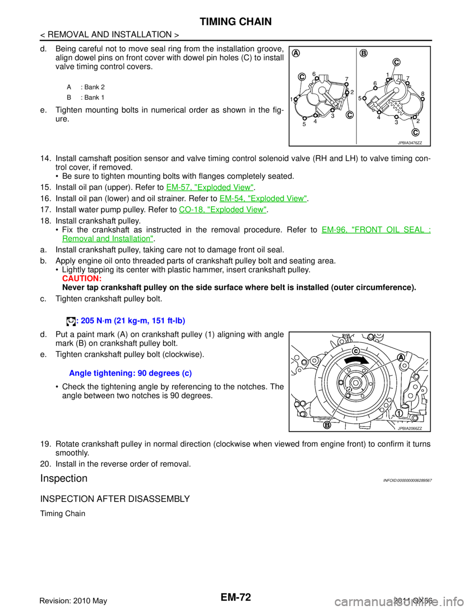
d. Being careful not to move seal ring from the installation groove,align dowel pins on front cover with dowel pin holes (C) to install
valve timing control covers.
e. Tighten mounting bolts in numerical order as shown in the fig- ure.
14. Install camshaft position sensor and valve timing c ontrol solenoid valve (RH and LH) to valve timing con-
trol cover, if removed.
Be sure to tighten mounting bolts with flanges completely seated.
15. Install oil pan (upper). Refer to EM-57, "
Exploded View".
16. Install oil pan (lower) and oil strainer. Refer to EM-54, "
Exploded View".
17. Install water pump pulley. Refer to CO-18, "
Exploded View".
18. Install crankshaft pulley. Fix the crankshaft as instructed in the removal procedure. Refer to EM-96, "
FRONT OIL SEAL :
Removal and Installation".
a. Install crankshaft pulley, taking care not to damage front oil seal.
b. Apply engine oil onto threaded parts of crankshaft pulley bolt and seating area. Lightly tapping its center with plastic hammer, insert crankshaft pulley.
CAUTION:
Never tap crankshaft pulley on the side surface wh ere belt is installed (outer circumference).
c. Tighten crankshaft pulley bolt.
d. Put a paint mark (A) on crankshaft pulley (1) aligning with angle mark (B) on crankshaft pulley bolt.
e. Tighten crankshaft pulley bolt (clockwise).
Check the tightening angle by referencing to the notches. Theangle between two notches is 90 degrees.
19. Rotate crankshaft pulley in normal direction (clockwise when viewed from engine front) to confirm it turns smoothly.
20. Install in the reverse order of removal.
InspectionINFOID:0000000006289567
INSPECTION AFTER DISASSEMBLY
Timing Chain
A: Bank 2
B: Bank 1
JPBIA3476ZZ
: 205 N·m (21 kg-m, 151 ft-lb)
Angle tightening: 90 degrees (c)
JPBIA2066ZZ
Revision: 2010 May2011 QX56