Page 2636 of 5598
EM-74
< REMOVAL AND INSTALLATION >
CAMSHAFT
CAMSHAFT
Exploded ViewINFOID:0000000006289568
1.VVEL actuator motor assembly
(bank 2) 2. Gasket 3.
VVEL actuator ho
using assembly
(bank 2)
4. Washer 5. VVEL ladder as sembly (bank 2) 6. Exhaust camshaft (bank 2)
7. Cylinder head (bank 2) 8. Cylinder head (bank 1) 9. Exhaust camshaft (bank 1)
10. VVEL ladder assembly (bank 1) 11. VVEL actuator housing assembly
(bank 1)12. Gasket
13. VVEL actuator motor assembly
(bank 1) 14.
VVEL control shaft
position sensor
(bank 1) 15.
VVEL control shaft
position sensor
(bank 2)
A. Comply with the installation proce-
dure when tightening. Refer to
EM-
75, "Removal and Installation".B. View B C. View C
Refer to GI-4, "
Components" for symbols in the figure.
JSBIA0403GB
Revision: 2010 May2011 QX56
Page 2637 of 5598

CAMSHAFTEM-75
< REMOVAL AND INSTALLATION >
C
DE
F
G H
I
J
K L
M A
EM
NP
O
Removal and InstallationINFOID:0000000006289569
REMOVAL
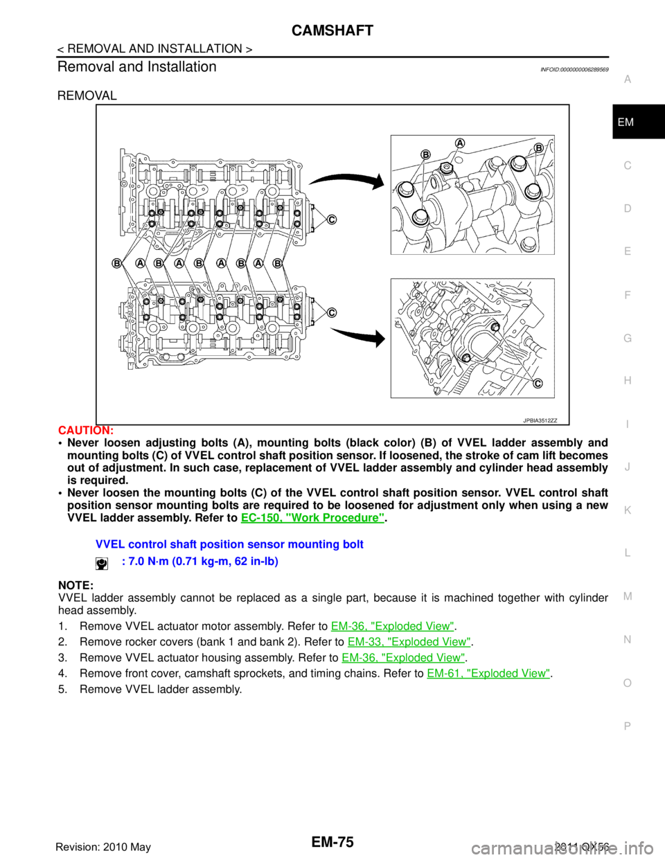
CAUTION:
Never loosen adjusting bolts (A), mounting bolt
s (black color) (B) of VVEL ladder assembly and
mounting bolts (C) of VVEL control shaft position sen sor. If loosened, the stroke of cam lift becomes
out of adjustment. In such case, replacement of VVEL ladder assembly and cylinder head assembly
is required.
Never loosen the mounting bolts (C) of the VVEL control shaft position sensor. VVEL control shaft
position sensor mounting bolts are required to be loosened for adjustment only when using a new
VVEL ladder assembly. Refer to EC-150, "
Work Procedure".
NOTE:
VVEL ladder assembly cannot be replaced as a singl e part, because it is machined together with cylinder
head assembly.
1. Remove VVEL actuator motor assembly. Refer to EM-36, "
Exploded View".
2. Remove rocker covers (bank 1 and bank 2). Refer to EM-33, "
Exploded View".
3. Remove VVEL actuator housing assembly. Refer to EM-36, "
Exploded View".
4. Remove front cover, camshaft sprockets, and timing chains. Refer to EM-61, "
Exploded View".
5. Remove VVEL ladder assembly.
JPBIA3512ZZ
VVEL control shaft positi on sensor mounting bolt
: 7.0 N·m (0.71 kg-m, 62 in-lb)
Revision: 2010 May2011 QX56
Page 2639 of 5598

CAMSHAFTEM-77
< REMOVAL AND INSTALLATION >
C
DE
F
G H
I
J
K L
M A
EM
NP
O
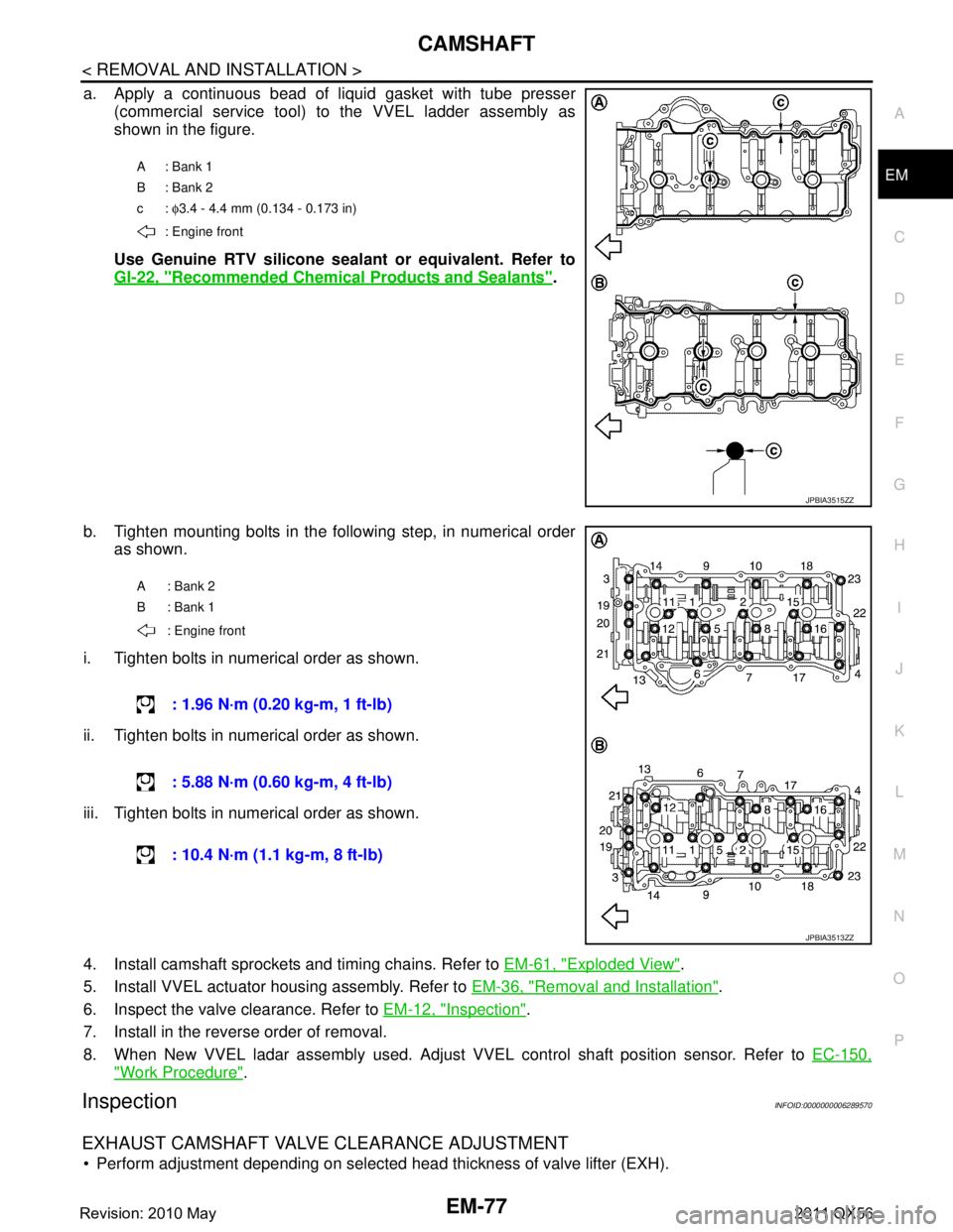
a. Apply a continuous bead of liquid gasket with tube presser
(commercial service tool) to the VVEL ladder assembly as
shown in the figure.
Use Genuine RTV silicone seal ant or equivalent. Refer to
GI-22, "
Recommended Chemical Products and Sealants".
b. Tighten mounting bolts in the following step, in numerical order as shown.
i. Tighten bolts in numerical order as shown.
ii. Tighten bolts in numerical order as shown.
iii. Tighten bolts in numerical order as shown.
4. Install camshaft sprockets and timing chains. Refer to EM-61, "
Exploded View".
5. Install VVEL actuator housing assembly. Refer to EM-36, "
Removal and Installation".
6. Inspect the valve clearance. Refer to EM-12, "
Inspection".
7. Install in the reverse order of removal.
8. When New VVEL ladar assembly used. Adjust VVEL control shaft position sensor. Refer to EC-150,
"Work Procedure".
InspectionINFOID:0000000006289570
EXHAUST CAMSHAFT VALVE CLEARANCE ADJUSTMENT
Perform adjustment depending on selected head thickness of valve lifter (EXH).
A: Bank 1
B: Bank 2
c: φ3.4 - 4.4 mm (0.134 - 0.173 in)
: Engine front
JPBIA3515ZZ
A: Bank 2
B: Bank 1
: Engine front
: 1.96 N·m (0.20 kg-m, 1 ft-lb)
: 5.88 N·m (0.60 kg-m, 4 ft-lb)
: 10.4 N·m (1.1 kg-m, 8 ft-lb)
JPBIA3513ZZ
Revision: 2010 May2011 QX56
Page 2978 of 5598

GI-14
< HOW TO USE THIS MANUAL >
ABBREVIATIONS
ABBREVIATIONS
Abbreviation ListINFOID:0000000006280882
The following ABBREVIATIONS are used:
A
B
C
D
ABBREVIATION DESCRIPTION
A/C Air conditioner
A/C Air conditioning
A/F sensor Air fuel ratio sensor A/T Automatic transaxle/transmission
ABS Anti-lock braking system
ACCS Advance climate control system ACL Air cleaner
AP Accelerator pedal
APP Accelerator pedal position ATF Automatic transmission fluid AV Audio visual
AWD All wheel drive
ABBREVIATION DESCRIPTION BARO Barometric pressureBCM Body control module
BLSD Brake limited slip differential BPP Brake pedal positionBSI Blind spot intervention
BSW Blind spot warning
ABBREVIATION DESCRIPTION CKP Crankshaft positionCL Closed loop
CMP Camshaft position CPP Clutch pedal positionCTP Closed throttle position
CVT Continuously Variable transaxle/transmission
ABBREVIATION DESCRIPTION D
1Drive range first gear
D
2Drive range second gear
D
3Drive range third gear
D
4Drive range fourth gear
DCA Distance control assist DFI Direct fuel injection system
DLC Data link connector
DTC Diagnostic trouble code
Revision: 2010 May2011 QX56