2011 INFINITI QX56 air condition
[x] Cancel search: air conditionPage 3036 of 5598
SQUEAK AND RATTLE TROUBLE DIAGNOSESGW-7
< SYMPTOM DIAGNOSIS >
C
DE
F
G H
I
J
L
M A
B
GW
N
O P
68370-4B000: 15 ×25 mm (0.59 ×0.98 in) pad/68239-13E00: 5 mm (0.20 in) wide tape roll
The following materials, not found in the kit, can also be used to repair squeaks and rattles.
UHMW (TEFLON) TAPE
Insulates where slight movement is present. Ideal for instrument panel applications.
SILICONE GREASE
Used in place of UHMW tape that will be visible or not fit. Will only last a few months.
SILICONE SPRAY
Use when grease cannot be applied.
DUCT TAPE
Use to eliminate movement.
CONFIRM THE REPAIR
Confirm that the cause of a noise is repaired by test driving the vehicle. Operate the vehicle under the same
conditions as when the noise originally occurred. Refer to the notes on the Diagnostic Worksheet.
Inspection ProcedureINFOID:0000000006108036
Refer to Table of Contents for specific component removal and installationinformation.
INSTRUMENT PANEL
Most incidents are caused by contact and movement between:
1. The cluster lid A and instrument panel
2. Acrylic lens and combination meter housing
3. Instrument panel to front pillar garnish
4. Instrument panel to windshield
5. Instrument panel mounting pins
6. Wiring harnesses behind the combination meter
7. A/C defroster duct and duct joint
These incidents can usually be located by tapping or moving the components to duplicate the noise or by
pressing on the components while driving to stop the noise. Most of these incidents can be repaired by
applying felt cloth tape or silicon spray (in hard to reach areas). Urethane pads can be used to insulate
wiring harness.
CAUTION:
Do not use silicone spray to isolate a squeak or rattle. If you saturatethe area with silicone, you
will not be able to recheck the repair.
CENTER CONSOLE
Components to pay attention to include:
1. Shifter assembly cover to finisher
2. A/C control unit and cluster lid C
3. Wiring harnesses behind audio and A/C control unit
The instrument panel repair and isolation procedures also apply to thecenter console.
DOORS
Pay attention to the:
1. Finisher and inner panel making a slapping noise
2. Inside handle escutcheon to door finisher
3. Wiring harnesses tapping
4. Door striker out of alignment causing a popping noise on startsand stops
Tapping or moving the components or pressing on them while driving to duplicate the conditions can isolate
many of these incidents. You can usually insulate the ar eas with felt cloth tape or insulator foam blocks from
the Nissan Squeak and Rattle Kit (J-43980) to repair the noise.
TRUNK
Trunk noises are often caused by a loose jack or loose items put intothe trunk by the owner.
In addition look for:
1. Trunk lid dumpers out of adjustment
2. Trunk lid striker out of adjustment
Revision: 2010 May2011 QX56
Page 3037 of 5598

GW-8
< SYMPTOM DIAGNOSIS >
SQUEAK AND RATTLE TROUBLE DIAGNOSES
3. The trunk lid torsion bars knocking together
4. A loose license plate or bracket
Most of these incidents can be repaired by adjusting, securing or insulatingthe item(s) or component(s) caus-
ing the noise.
SUNROOF/HEADLINING
Noises in the sunroof/headlining area c an often be traced to one of the following:
1. Sunroof lid, rail, linkage or seals making a rattle or light knockingnoise
2. Sunvisor shaft shaking in the holder
3. Front or rear windshield touching headlining and squeaking
Again, pressing on the components to stop the noise while duplicatingthe conditions can isolate most of these
incidents. Repairs usually consistof insulating with felt cloth tape.
SEATS
When isolating seat noise it's important to note the pos ition the seatis in and the load placed on the seat when
the noise is present. These conditionsshould be duplic ated when verifying and isolating the cause of the
noise.
Cause of seat noise include:
1. Headrest rods and holder
2. A squeak between the seat pad cushion and frame
3. The rear seatback lock and bracket
These noises can be isolated by moving or pressing on the suspectedcomponents while duplicating the condi-
tions under which the noise occurs. Most of these incidents can be repaired by repositioning the component
orapplying urethane tape to the contact area.
UNDERHOOD
Some interior noise may be caused by components under the hood or onthe engine wall. The noise is then
transmitted into the passenger compartment.
Causes of transmitted underhood noise include:
1. Any component mounted to the engine wall
2. Components that pass through the engine wall
3. Engine wall mounts and connectors
4. Loose radiator mounting pins
5. Hood bumpers out of adjustment
6. Hood striker out of adjustment
These noises can be difficult to isolate since they cannot be reached from the interior of the vehicle. The best
method is to secure, move or insulate one component at a time and test drive the \
vehicle. Also, engine RPM
or load can be changed to isolate the noise. Repairs can usually be made by moving, adjusting, securing, or
insulating the component causing the noise.
Revision: 2010 May2011 QX56
Page 3057 of 5598

HA-1
VENTILATION, HEATER & AIR CONDITIONER
C
DE
F
G H
J
K L
M
SECTION HA
A
B
HA
N
O P
CONTENTS
HEATER & AIR CONDITIONING SYSTEM
PRECAUTION ................ ...............................3
PRECAUTIONS .............................................. .....3
Precaution for Supplemental Restraint System
(SRS) "AIR BAG" and "SEAT BELT PRE-TEN-
SIONER" ............................................................. ......
3
Precaution Necessary for Steering Wheel Rota-
tion after Battery Disconnect .....................................
3
Precaution for Procedure without Cowl Top Cover ......4
Precautions For Refrigerant System Service ............4
Service Equipment ....................................................6
PREPARATION ............................................9
PREPARATION .............................................. .....9
Special Service Tool ........................................... ......9
Commercial Service Tool ........................................12
Sealant or/and Lubricant .........................................12
SYSTEM DESCRIPTION .............................13
COMPONENT PARTS ................................... ....13
Component Parts Location .................................. ....13
Component Description ...........................................13
SYSTEM .............................................................14
System Diagram .................................................. ....14
System Description .................................................14
BASIC INSPECTION ...................................16
DIAGNOSIS AND REPAIR WORKFLOW ..... ....16
Work Flow ........................................................... ....16
REFRIGERANT ..................................................18
Description .......................................................... ....18
Leak Test ................................................................18
Recycle Refrigerant .................................................20
Charge Refrigerant ..................................................20
LUBRICANT ................................................... ....22
Description .......................................................... ....22
Inspection ............................................................ ....22
Perform Lubricant Return Operation .......................22
Lubricant Adjusting Procedure for Components
Replacement Except Compressor ...........................
22
Lubricant Adjusting Procedure for Compressor
Replacement ...........................................................
23
PERFORMANCE TEST ....................................25
Inspection ................................................................25
SYMPTOM DIAGNOSIS ..............................27
REFRIGERATION SYSTEM SYMPTOMS ........27
Trouble Diagnosis For Unusual Pressure ............ ....27
Symptom Table .......................................................27
NOISE ................................................................29
Symptom Table .......................................................29
REMOVAL AND INSTALLATION ...............30
COMPRESSOR .................................................30
Exploded View ..................................................... ....30
COMPRESSOR ..........................................................30
COMPRESSOR : Removal and Installation ............30
MAGNET CLUTCH ................................................ ....31
MAGNET CLUTCH : Removal and Installation of
Compressor Clutch ..................................................
31
Inspection ................................................................32
COOLER PIPE AND HOSE ..............................33
Exploded View .........................................................33
HIGH-PRESSURE FLEXIBLE HOSE ........................34
HIGH-PRESSURE FLEXIBLE HOSE : Removal
and Installation .................................................... ....
34
LOW-PRESSURE FLEXIBLE HOSE ..................... ....35
LOW-PRESSURE FLEXIBLE HOSE : Removal
and Installation ........................................................
35
HIGH-PRESSURE PIPE ............................................35
Revision: 2010 May2011 QX56
Page 3060 of 5598
HA-4
< PRECAUTION >
PRECAUTIONS
5. When the repair work is completed, re-connect both battery cables. With the brake pedal released, turn
the push-button ignition switch from ACC position to ON position, then to LOCK position. (The steering
wheel will lock when the push-button igniti on switch is turned to LOCK position.)
6. Perform self-diagnosis check of all control units using CONSULT-III.
Precaution for Procedure without Cowl Top CoverINFOID:0000000006276138
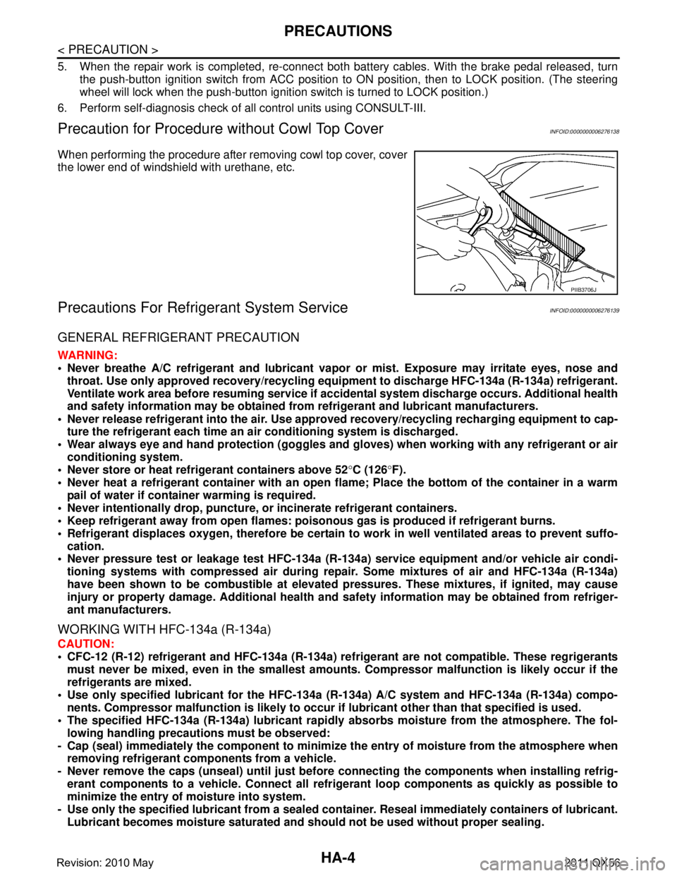
When performing the procedure after removing cowl top cover, cover
the lower end of windshield with urethane, etc.
Precautions For Refrigerant System ServiceINFOID:0000000006276139
GENERAL REFRIGERANT PRECAUTION
WARNING:
Never breathe A/C refrigerant an d lubricant vapor or mist. Exposure may irritate eyes, nose and
throat. Use only approved reco very/recycling equipment to discharge HFC-134a (R-134a) refrigerant.
Ventilate work area before resuming service if acci dental system discharge occurs. Additional health
and safety information may be obtained from refrigerant and lubricant manufacturers.
Never release refrigerant into the air. Use appro ved recovery/recycling recharging equipment to cap-
ture the refrigerant each time an ai r conditioning system is discharged.
Wear always eye and hand protection (goggles and gloves) when working with any refrigerant or air
conditioning system.
Never store or heat refrigerant containers above 52 °C (126 °F).
Never heat a refrigerant container with an open flame; Place the bottom of the container in a warm
pail of water if container warming is required.
Never intentionally drop, puncture, or incinerate refrigerant containers.
Keep refrigerant away from open flames: pois onous gas is produced if refrigerant burns.
Refrigerant displaces oxygen, therefore be certain to work in well ventilated areas to prevent suffo-
cation.
Never pressure test or leakage test HFC-134a (R- 134a) service equipment and/or vehicle air condi-
tioning systems with compressed air during repair. Some mixtures of air and HFC-134a (R-134a)
have been shown to be combusti ble at elevated pressures. These mixtures, if ignited, may cause
injury or property damage. Additional health and safety information may be obtained from refriger-
ant manufacturers.
WORKING WITH HFC-134a (R-134a)
CAUTION:
CFC-12 (R-12) refrigerant and HFC-134a (R-134a) re frigerant are not compatible. These regrigerants
must never be mixed, even in the smallest amount s. Compressor malfunction is likely occur if the
refrigerants are mixed.
Use only specified lubricant for the HFC-134a (R-134a) A/C system and HFC-134a (R-134a) compo-
nents. Compressor malfunction is likely to occur if lubricant other than that specified is used.
The specified HFC-134a (R-134a) lu bricant rapidly absorbs moisture from the atmosphere. The fol-
lowing handling precauti ons must be observed:
- Cap (seal) immediately the compon ent to minimize the entry of moisture from the atmosphere when
removing refrigerant components from a vehicle.
- Never remove the caps (unseal) until just before co nnecting the components when installing refrig-
erant components to a vehicle. Connect all refr igerant loop components as quickly as possible to
minimize the entry of moisture into system.
- Use only the specified lubricant from a sealed contai ner. Reseal immediately containers of lubricant.
Lubricant becomes moisture saturated and should not be used without proper sealing.
PIIB3706J
Revision: 2010 May2011 QX56
Page 3061 of 5598
PRECAUTIONSHA-5
< PRECAUTION >
C
DE
F
G H
J
K L
M A
B
HA
N
O P
- Never allow lubricant (A/C System Oil Type R) to come in contact with styrene foam parts. Damage
may result.
REFRIGERANT CONNECTION
A new type refrigerant connection has been introduced to a ll refrigerant lines except the following location.
Expansion valve to evaporator
Refrigerant pressure sensor to liquid tank
WARNING:
Check that all refrigerant is discharged into the recycling equipment and the pressure in the system is
less than atmospheric pressure. Then gradually loo sen the discharge side hose fitting and remove it.
CAUTION:
Observe the following when replacing or cleaning refrigerant cycle components.
Store it in the same way at it is when mounted on the car when the compressor is removed. Failure
to do so will cause lubricant to enter the low-pressure chamber.
Use always a torque wrench and a b ack-up wrench when connecting tubes.
Plug immediately all openings to prevent entry of dust and mois ture after disconnecting tubes.
Connect the pipes at the final stag e of the operation when installing an air conditioner in the vehicle.
Never remove the seal caps of pipes and other compon ents until just before required for connection.
Allow components stored in cool areas to warm to working area temperature before removing seal
caps. This prevents condensation from forming inside A/C components.
Remove thoroughly moisture from the refriger ation system before charging the refrigerant.
Replace always used O-rings.
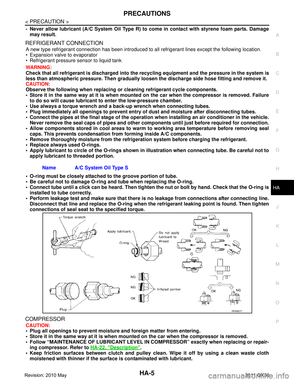
Apply lubricant to circle of th e O-rings shown in illustration when connecting tube. Be careful not to
apply lubricant to threaded portion.
O-ring must be closely attached to the groove portion of tube.
Be careful not to damage O-ring and tube when replacing the O-ring.
Connect tube until a click can be heard. Then tighten the nut or bolt by hand. Check that the O-ring is
installed to tube correctly.
Perform leakage test and make sure that there is no leakage from connections after connecting line.
Disconnect that line and replace the O-ring when the refrigerant leaking point is found. Then tighten
connections of seal seat to the specified torque.
COMPRESSOR
CAUTION:
Plug all openings to prevent moisture and foreign matter from entering.
Store it in the same way at it is when moun ted on the car when the compressor is removed.
Follow “MAINTENANCE OF LUBRICANT LEVEL IN CO MPRESSOR” exactly when replacing or repair-
ing compressor. Refer to HA-22, "
Description".
Keep friction surfaces between clutch and pulley cl ean. Wipe it off by using a clean waste cloth
moistened with thinner if the surface is contaminated with lubricant.
Name A/C System Oil Type S
RHA861F
Revision: 2010 May2011 QX56
Page 3071 of 5598

SYSTEMHA-15
< SYSTEM DESCRIPTION >
C
DE
F
G H
J
K L
M A
B
HA
N
O P
The refrigerant from the compressor, frows the condens er with liquid tank, the evaporator, and returns to the
compressor. The refrigerant evaporation in the evaporator is controlled by an expansion valve.
Freeze Protection
Automatic air conditioner When intake sensor detects that evaporator surface temperature is 2.5°C (37 °F) or less, A/C auto amp.
requests BCM to turn the compressor OFF.
BCM requests ECM to turn the compressor to OFF by the signal from A/C auto amp., and ECM makes A/C
relay to OFF, and stops the compressor.
REFRIGERANT SYSTEM PROTECTION
Refrigerant Pressure Sensor
The refrigerant system is protected against excessively high- or low-pressures by the refrigerant pressure
sensor, installed at the condenser exit. The refrigerant pressure sensor detects the pressure inside the
refrigerant line and sends the voltage signal to the ECM if the system pressure rises above, or falls below
the specifications.
ECM turns the A/C relay to OFF and stops the compress or when the high-pressure side detected by refriger-
ant pressure sensor is following conditions;
- Approximately 3,120 kPa (31.8 kg/cm
2, 452 psi) or more (Engine speed is less than 1,500 rpm.)
- Approximately 2,740 kPa (27.9 kg/cm
2, 397 psi) or more (Engine speed is 1,500 rpm or more.)
- Approximately 140 kPa (1.4 kg/cm
2, 20 psi) or less
Pressure Relief Valve
The refrigerant system is also protected by a pressure relief valve, located in the rear head of the compressor.
The release port on the pressure relief valve automatical ly opens and releases refrigerant into the atmosphere
when the pressure of refrigerant in the system incr eases to an unusual level [more than 3,800 kPa (38.8 kg/
cm
2, 551 psi)].
Revision: 2010 May2011 QX56
Page 3075 of 5598
REFRIGERANTHA-19
< BASIC INSPECTION >
C
DE
F
G H
J
K L
M A
B
HA
N
O P
Never look directly into UV lamp light source.
NOTE:
For continuous operating time of UV lamp, fo llow the manufacturer operating instructions.
Illuminate piping joints from different angles us ing UV lamp and check that there is no leakage.
Use a mirror in area that is difficult to see to check refrigerant leakage.
Refrigerant leakage from evaporator can be detected by soaking cotton swab or a similar material with
drain hose water and illuminating it using UV lamp.
Dust, dirt, and packing materials adhesive used for condenser, evaporator, and other locations may flu- oresce. Be careful not to misidentify leakage.
5. Repair or replace parts where refrigerant leak age occurs and wipe off fluorescent leak detection dye.
NOTE:
Completely wipe off fluorescent leak detection dy e from gaps between parts, screw threads, and others
using a cotton swab or similar materials.
6. Use a UV lamp to check that no fluorescent leak detection dye remains after finishing work. WARNING:
Never look directly into UV lamp light source.
NOTE:
For continuous operating time of UV lamp, fo llow the manufacturer operating instructions.
Dust, dirt, and packing materials adhesive used for condenser, evaporator, and other locations may flu-
oresce. Be careful not to misidentify leakage.
CHECK REFRIGERANT LEAKAGE USIN G ELECTRICAL LEAK DETECTOR
WARNING:
Never check refrigerant leakage while the engine is running.
CAUTION:
Be careful of the following items so that in accurate checks or misidentifications are avoided.
Never allow refrigerant vapor, shop chemical vapors, cigarette smoke, or others around the vehicle.
Always check refrigerant leakage in a low air flow environment so that refrigerant may not disperse
when leakage occurs.
1. Stop the engine.
2. Connect recovery/recycling/recharging equipment or manifold gauge set to A/C service valve.
3. Check that A/C refrigerant pressure is 345 kPa (3.52 kg/cm
2, 50 psi) or more when temperature is 16 °C
(61 °F) or more. When pressure is lower than the spec ified value, recycle refrigerant completely and fill
refrigerant to the specified level.
NOTE:
Leakages may not be detected if A/C refri gerant pressure is 345 kPa (3.52 kg/cm
2, 50 psi) or less when
temperature is less than 16 °C (61 °F).
4. Clean area where refrigerant leakage check is per formed, and check refrigerant leakage along all sur-
faces of pipe connections and A/C system com ponents using electrical leak detector probe.
CAUTION:
Continue checking when a leakage is found. Always continue and complete checking along all
pipe connections and A/C system co mponents for additional leakage.
When a leakage is detected, clean leakage area using compressed air and check again.
When checking leakage of cooling unit inside, al ways clean inside of drain hose so that the
probe surface may not be exposed to water or dirt.
NOTE:
Always check leakage starting from high-pressure side and continue to low-pressure side.
When checking leakage of cooling unit inside, operate blower fan motor for 15 minutes or more at the maximum fan speed while the engine is stopped, and then insert electrical leak detector probe into drain
hose and hold for 10 minutes or more.
When disconnecting shut-off valve that is connected to A/C service valve, always evacuate remaining
refrigerant so that misidentification can be avoided.
5. Repair or replace parts where refrigerant leak age is detected. (Leakage is detected but leakage area is
unknown. GO TO 6.)
6. Start the engine and set A/C control in the following conditions. A/C switch ON
Air flow: VENT (ventilation)
Intake door position: Recirculation
Revision: 2010 May2011 QX56
Page 3081 of 5598
PERFORMANCE TESTHA-25
< BASIC INSPECTION >
C
DE
F
G H
J
K L
M A
B
HA
N
O P
PERFORMANCE TEST
InspectionINFOID:0000000006276158
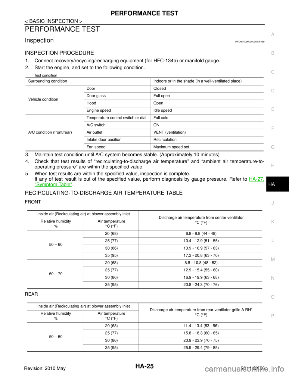
INSPECTION PROCEDURE
1. Connect recovery/recycling/recharging equipment (for HFC-134a) or manifold gauge.
2. Start the engine, and set to the following condition.
Test condition
3. Maintain test condition until A/C system becomes stable. (Approximately 10 minutes)
4. Check that test results of “recirculating-to-disc harge air temperature” and “ambient air temperature-to-
operating pressure” are within the specified value.
5. When test results are within the specified value, inspection is complete. If any of test result is out of the specified value, perform diagnosis by gauge pressure. Refer to HA-27,
"Symptom Table".
RECIRCULATING-TO-DISCHARGE AIR TEMPERATURE TABLE
FRONT
REAR
Surrounding condition Indoors or in the shade (in a well-ventilated place)
Vehicle conditionDoor Closed
Door glass Full open
Hood Open
Engine speed Idle speed
A/C condition (front/rear) Temperature control switch or dial Full cold
A/C switch ON
Air outlet VENT (ventilation)
Intake door position Recirculation
Fan speed Maximum speed set
Inside air (Recirculating air) at blower assembly inlet
Discharge air temperature from center ventilator
°C ( °F)
Relative humidity
% Air temperature
°C ( °F)
50 – 60 20 (68) 6.8 - 8.8 (44 - 48)
25 (77) 10.4 -
12.9 (51 - 55)
30 (86) 13.9 - 16.9 (57 - 63)
35 (95) 17.3 - 20.8 (63 - 70)
60 – 70 20 (68) 8.8 - 10.8 (48 - 52)
25 (77) 12.9 -
15.4 (55 - 60)
30 (86) 16.9 - 19.9 (63 - 68)
35 (95) 20.8 - 24.3 (70 - 76)
Inside air (Recirculating air) at blower assembly inlet
Discharge air temperature from rear ventilator grille A RH*
°C ( °F)
Relative humidity
% Air temperature
°C ( °F)
50 – 60 20 (68) 11.4 -
13.4 (53 - 56)
25 (77) 15.8 - 18.3 (60 - 65)
30 (86) 20.9 - 23.9 (70 - 75)
35 (95) 25.9 - 29.4 (79 - 85)
Revision: 2010 May2011 QX56