2011 INFINITI QX56 lock
[x] Cancel search: lockPage 4156 of 5598
KEYLESS POWER WINDOW DOWN DOES NOT OPERATE
PWC-71
< SYMPTOM DIAGNOSIS >
C
D E
F
G H
I
J
L
M A
B
PWC
N
O P
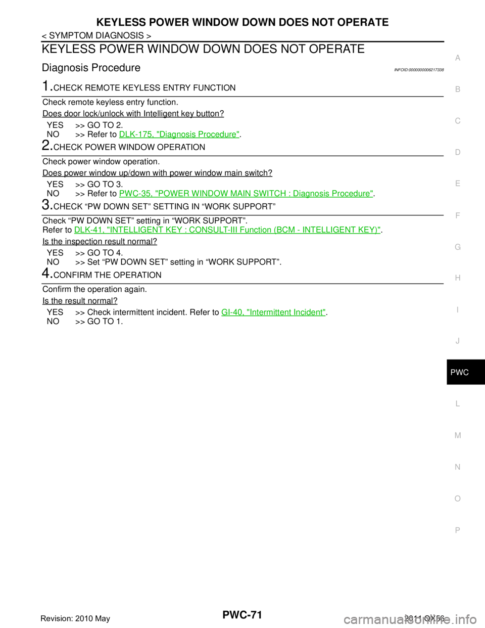
KEYLESS POWER WINDOW DOWN DOES NOT OPERATE
Diagnosis ProcedureINFOID:0000000006217338
1.CHECK REMOTE KEYLESS ENTRY FUNCTION
Check remote keyless entry function.
Does door lock/unlock with Intelligent key button?
YES >> GO TO 2.
NO >> Refer to DLK-175, "
Diagnosis Procedure".
2.CHECK POWER WINDOW OPERATION
Check power window operation.
Does power window up/down with power window main switch?
YES >> GO TO 3.
NO >> Refer to PWC-35, "
POWER WINDOW MAIN SWITCH : Diagnosis Procedure".
3.CHECK “PW DOWN SET” SETTING IN “WORK SUPPORT”
Check “PW DOWN SET” setting in “WORK SUPPORT”.
Refer to DLK-41, "
INTELLIGENT KEY : CONSULT-III F unction (BCM - INTELLIGENT KEY)".
Is the inspection result normal?
YES >> GO TO 4.
NO >> Set “PW DOWN SET” setting in “WORK SUPPORT”.
4.CONFIRM THE OPERATION
Confirm the operation again.
Is the result normal?
YES >> Check intermittent incident. Refer to GI-40, "Intermittent Incident".
NO >> GO TO 1.
Revision: 2010 May2011 QX56
Page 4157 of 5598
PWC-72
< SYMPTOM DIAGNOSIS >
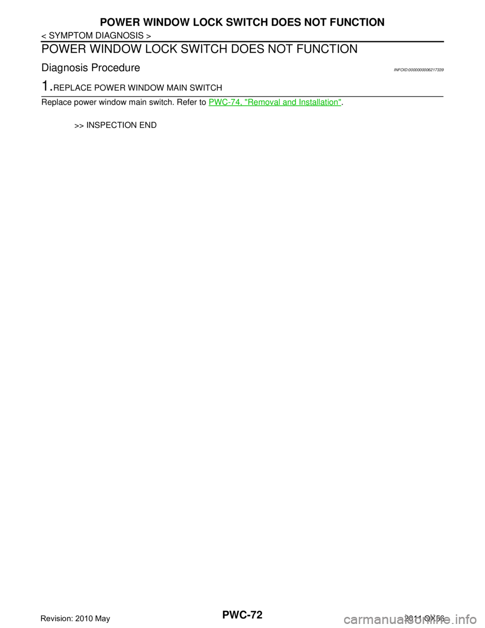
POWER WINDOW LOCK SWITCH DOES NOT FUNCTION
POWER WINDOW LOCK SWITCH DOES NOT FUNCTION
Diagnosis ProcedureINFOID:0000000006217339
1.REPLACE POWER WINDOW MAIN SWITCH
Replace power window main switch. Refer to PWC-74, "
Removal and Installation".
>> INSPECTION END
Revision: 2010 May2011 QX56
Page 4203 of 5598
REAR WHEEL HUB AND HOUSINGRAX-7
< REMOVAL AND INSTALLATION >
CEF
G H
I
J
K L
M A
B
RAX
N
O P
REMOVAL AND INSTALLATION
REAR WHEEL HUB AND HOUSING
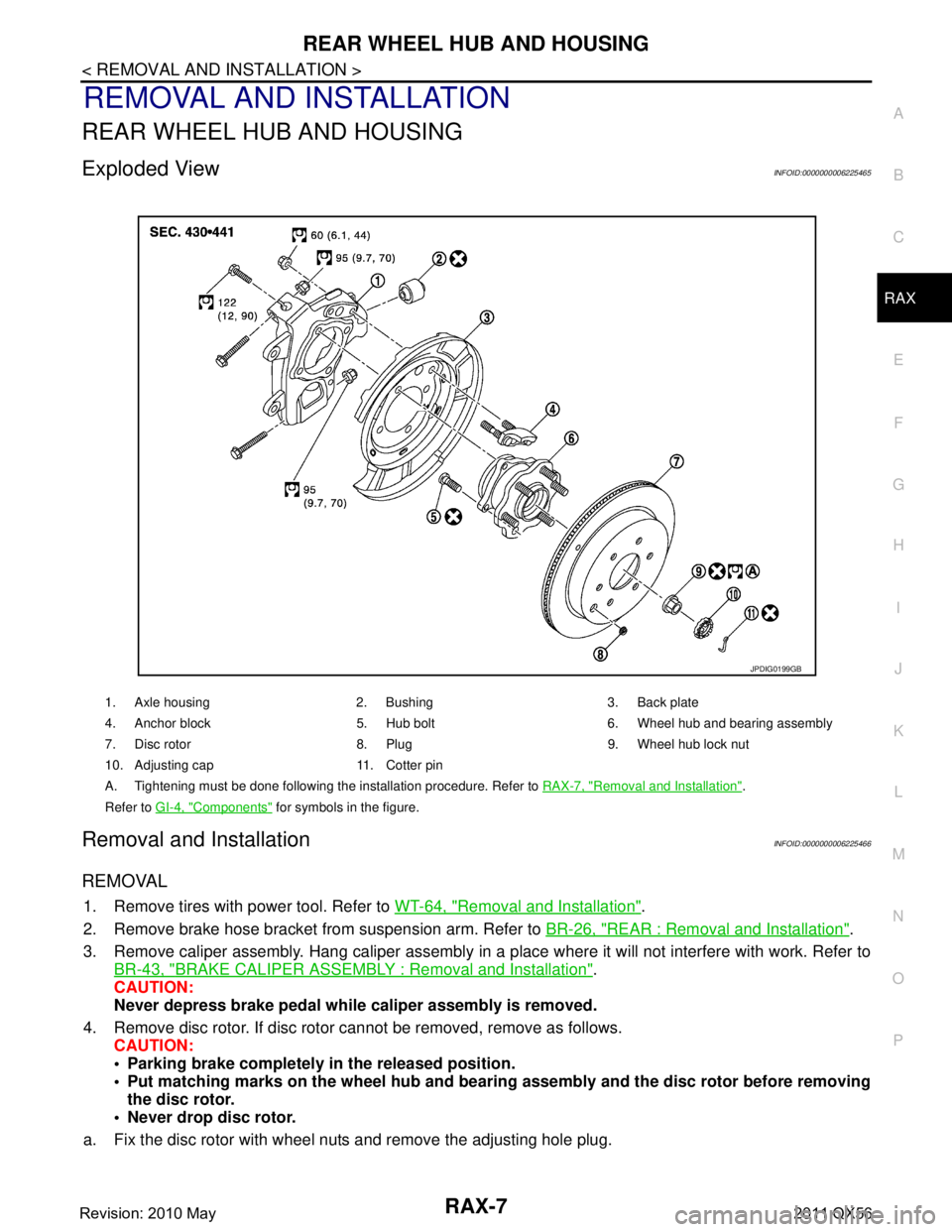
Exploded ViewINFOID:0000000006225465
Removal and InstallationINFOID:0000000006225466
REMOVAL
1. Remove tires with power tool. Refer to WT-64, "Removal and Installation".
2. Remove brake hose bracket from suspension arm. Refer to BR-26, "
REAR : Removal and Installation".
3. Remove caliper assembly. Hang caliper assembly in a place where it will not interfere with work. Refer to BR-43, "
BRAKE CALIPER ASSEMBLY : Removal and Installation".
CAUTION:
Never depress brake pedal while caliper assembly is removed.
4. Remove disc rotor. If disc rotor cannot be removed, remove as follows. CAUTION:
• Parking brake completely in the released position.
Put matching marks on the wheel hub and bear ing assembly and the disc rotor before removing
the disc rotor.
Never drop disc rotor.
a. Fix the disc rotor with wheel nuts and remove the adjusting hole plug.
1. Axle housing 2. Bushing 3. Back plate
4. Anchor block 5. Hub bolt 6. Wheel hub and bearing assembly
7. Disc rotor 8. Plug 9. Wheel hub lock nut
10. Adjusting cap 11. Cotter pin
A. Tightening must be done following the installation procedure. Refer to RAX-7, "
Removal and Installation".
Refer to GI-4, "
Components" for symbols in the figure.
JPDIG0199GB
Revision: 2010 May2011 QX56
Page 4204 of 5598
RAX-8
< REMOVAL AND INSTALLATION >
REAR WHEEL HUB AND HOUSING
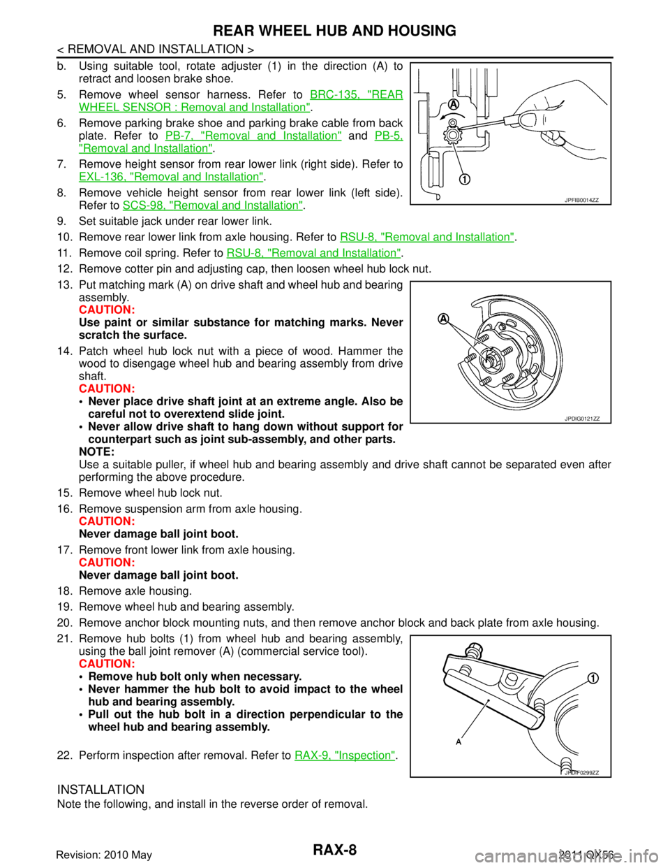
b. Using suitable tool, rotate adjuster (1) in the direction (A) toretract and loosen brake shoe.
5. Remove wheel sensor harness. Refer to BRC-135, "
REAR
WHEEL SENSOR : Removal and Installation".
6. Remove parking brake shoe and parking brake cable from back plate. Refer to PB-7, "
Removal and Installation" and PB-5,
"Removal and Installation".
7. Remove height sensor from rear lower link (right side). Refer to EXL-136, "
Removal and Installation".
8. Remove vehicle height sensor from rear lower link (left side). Refer to SCS-98, "
Removal and Installation".
9. Set suitable jack under rear lower link.
10. Remove rear lower link from axle housing. Refer to RSU-8, "
Removal and Installation".
11. Remove coil spring. Refer to RSU-8, "
Removal and Installation".
12. Remove cotter pin and adjusting cap, then loosen wheel hub lock nut.
13. Put matching mark (A) on drive shaft and wheel hub and bearing assembly.
CAUTION:
Use paint or similar substance for matching marks. Never
scratch the surface.
14. Patch wheel hub lock nut with a piece of wood. Hammer the wood to disengage wheel hub and bearing assembly from drive
shaft.
CAUTION:
Never place drive shaft joint at an extreme angle. Also be
careful not to over extend slide joint.
Never allow drive shaft to ha ng down without support for
counterpart such as joint sub-assembly, and other parts.
NOTE:
Use a suitable puller, if wheel hub and bearing assembly and drive shaft cannot be separated even after
performing the above procedure.
15. Remove wheel hub lock nut.
16. Remove suspension arm from axle housing. CAUTION:
Never damage ball joint boot.
17. Remove front lower link from axle housing. CAUTION:
Never damage ball joint boot.
18. Remove axle housing.
19. Remove wheel hub and bearing assembly.
20. Remove anchor block mounting nuts, and then remove anchor block and back plate from axle housing.
21. Remove hub bolts (1) from wheel hub and bearing assembly, using the ball joint remover (A) (commercial service tool).
CAUTION:
Remove hub bolt only when necessary.
Never hammer the hub bolt to avoid impact to the wheel
hub and bearing assembly.
Pull out the hub bolt in a direction perpendicular to the wheel hub and bearing assembly.
22. Perform inspection after removal. Refer to RAX-9, "
Inspection".
INSTALLATION
Note the following, and install in the reverse order of removal.
JPFIB0014ZZ
JPDIG0121ZZ
JPDIF0299ZZ
Revision: 2010 May2011 QX56
Page 4205 of 5598
REAR WHEEL HUB AND HOUSINGRAX-9
< REMOVAL AND INSTALLATION >
CEF
G H
I
J
K L
M A
B
RAX
N
O P
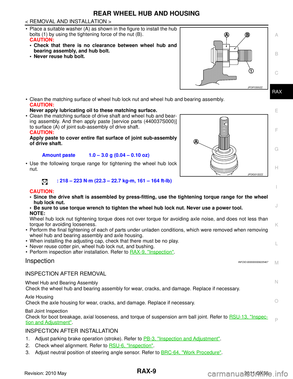
Place a suitable washer (A) as shown in the figure to install the hub bolts (1) by using the tightening force of the nut (B).
CAUTION:
Check that there is no cl earance between wheel hub and
bearing assembly, and hub bolt.
Never reuse hub bolt.
Clean the matching surface of wheel hub lock nut and wheel hub and bearing assembly. CAUTION:
Never apply lubricating oi l to these matching surface.
Clean the matching surface of drive shaft and wheel hub and bear-
ing assembly. And then apply paste [service parts (440037S000)]
to surface (A) of joint sub-assembly of drive shaft.
CAUTION:
Apply paste to cover entire fl at surface of joint sub-assembly
of drive shaft.
Use the following torque range for tightening the wheel hub lock nut.
CAUTION:
Since the drive shaft is assembled by press-fitting , use the tightening torque range for the wheel
hub lock nut.
Be sure to use torque wrench to tighten th e wheel hub lock nut. Never use a power tool.
NOTE:
Wheel hub lock nut tightening torque does not over tor que for avoiding axle noise, and does not less than
torque for avoiding looseness.
Perform the final tightening of each of parts under unladen conditions, which were removed when removing wheel hub and bearing assembly and axle housing.
When installing the adjusting cap, check that there must be no play.
Never reuse cotter pin, wheel hub lock nut, and bushing.
Perform inspection after installation. Refer to RAX-9, "
Inspection".
InspectionINFOID:0000000006225467
INSPECTION AFTER REMOVAL
Wheel Hub and Bearing Assembly
Check the wheel hub and bearing assembly for wear, cracks, and damage. Replace if necessary.
Axle Housing
Check the axle housing for wear, cracks, and damage. Replace if necessary.
Ball Joint Inspection
Check for boot breakage, axial looseness, and torque of suspension arm ball joint. Refer to RSU-13, "Inspec-
tion and Adjustment".
INSPECTION AFTER INSTALLATION
1. Adjust parking brake operation (stroke). Refer to PB-3, "Inspection and Adjustment".
2. Check wheel alignment. Refer to RSU-6, "
Inspection".
3. Adjust neutral position of steering angle sensor. Refer to BRC-64, "
Work Procedure".
JPDIF0300ZZ
Amount paste 1.0 – 3.0 g (0.04 – 0.10 oz)
: 218 – 223 N·m (22.3 – 22.7 kg-m, 161 – 164 ft-lb)
JPDIG0122ZZ
Revision: 2010 May2011 QX56
Page 4207 of 5598
REAR DRIVE SHAFTRAX-11
< REMOVAL AND INSTALLATION >
CEF
G H
I
J
K L
M A
B
RAX
N
O P
REAR DRIVE SHAFT
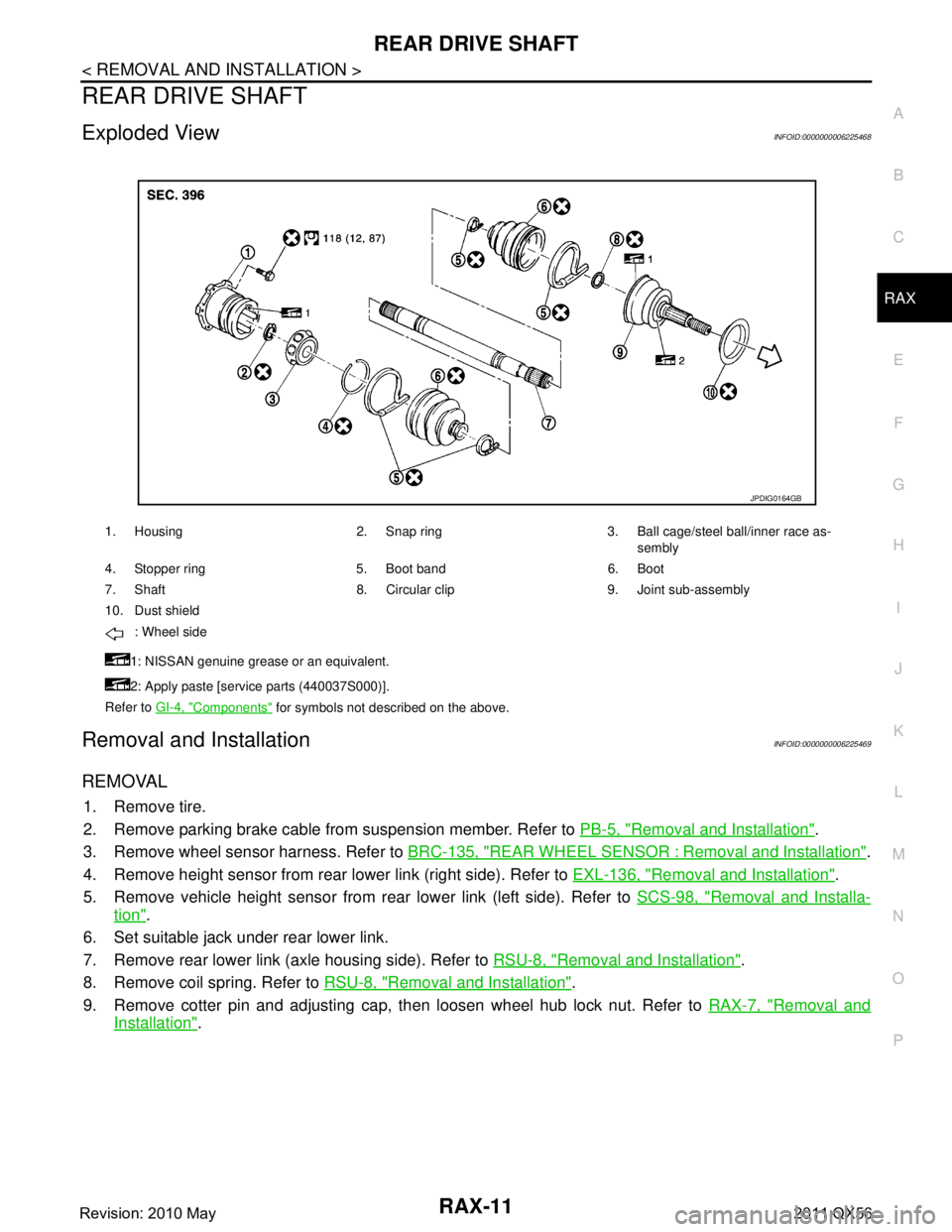
Exploded ViewINFOID:0000000006225468
Removal and InstallationINFOID:0000000006225469
REMOVAL
1. Remove tire.
2. Remove parking brake cable from suspension member. Refer to PB-5, "
Removal and Installation".
3. Remove wheel sensor harness. Refer to BRC-135, "
REAR WHEEL SENSOR : Removal and Installation".
4. Remove height sensor from rear lower link (right side). Refer to EXL-136, "
Removal and Installation".
5. Remove vehicle height sensor from rear lower link (left side). Refer to SCS-98, "
Removal and Installa-
tion".
6. Set suitable jack under rear lower link.
7. Remove rear lower link (axle housing side). Refer to RSU-8, "
Removal and Installation".
8. Remove coil spring. Refer to RSU-8, "
Removal and Installation".
9. Remove cotter pin and adjusting cap, then loosen wheel hub lock nut. Refer to RAX-7, "
Removal and
Installation".
1. Housing 2. Snap ring 3. Ball cage/steel ball/inner race as-
sembly
4. Stopper ring 5. Boot band 6. Boot
7. Shaft 8. Circular clip 9. Joint sub-assembly
10. Dust shield : Wheel side
1: NISSAN genuine grease or an equivalent.
2: Apply paste [service parts (440037S000)].
Refer to GI-4, "
Components" for symbols not described on the above.
JPDIG0164GB
Revision: 2010 May2011 QX56
Page 4208 of 5598
RAX-12
< REMOVAL AND INSTALLATION >
REAR DRIVE SHAFT
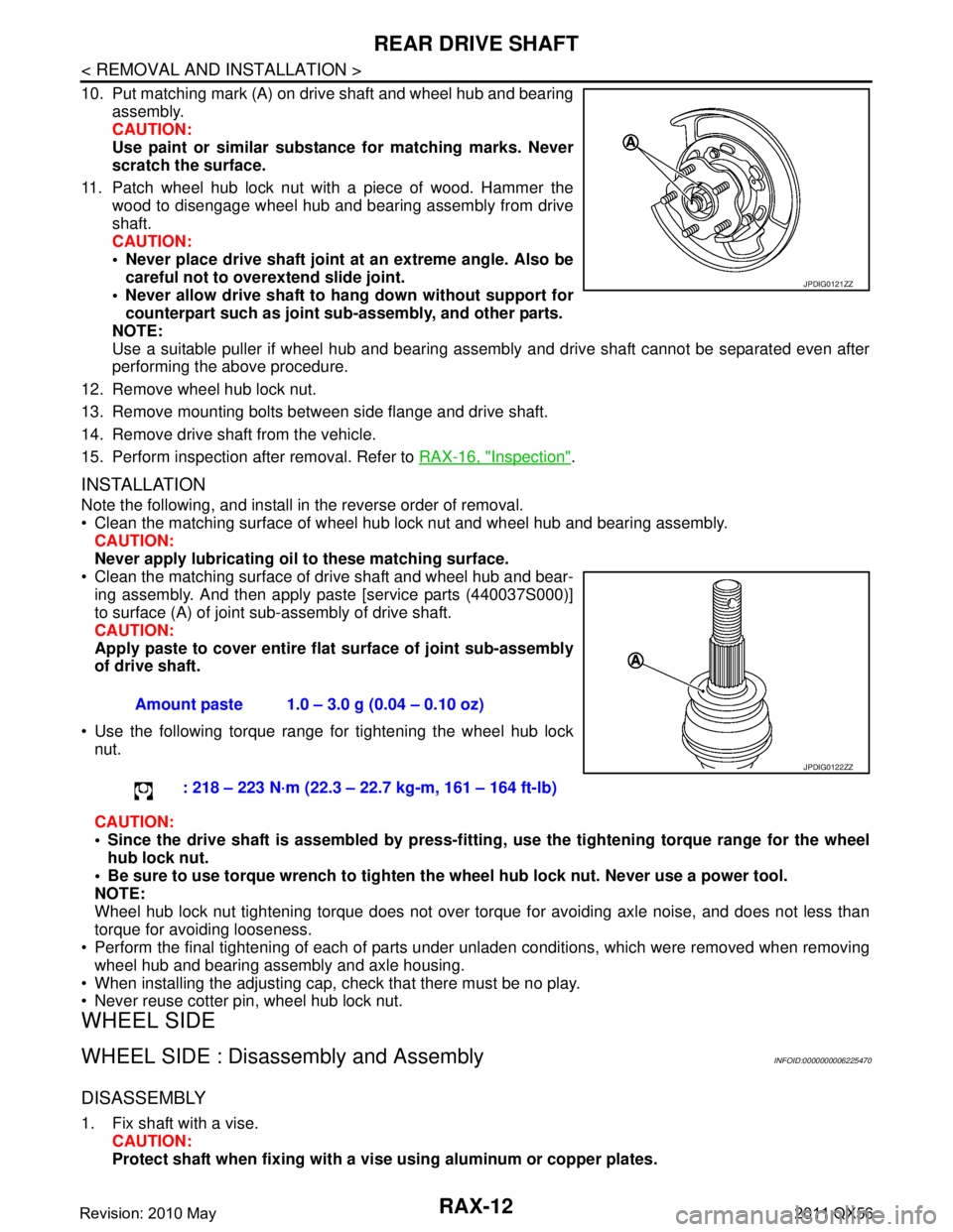
10. Put matching mark (A) on drive shaft and wheel hub and bearingassembly.
CAUTION:
Use paint or similar substance for matching marks. Never
scratch the surface.
11. Patch wheel hub lock nut with a piece of wood. Hammer the wood to disengage wheel hub and bearing assembly from drive
shaft.
CAUTION:
Never place drive shaft joint at an extreme angle. Also becareful not to over extend slide joint.
Never allow drive shaft to ha ng down without support for
counterpart such as joint sub-assembly, and other parts.
NOTE:
Use a suitable puller if wheel hub and bearing assembly and drive shaft cannot be separated even after
performing the above procedure.
12. Remove wheel hub lock nut.
13. Remove mounting bolts between side flange and drive shaft.
14. Remove drive shaft from the vehicle.
15. Perform inspection after removal. Refer to RAX-16, "
Inspection".
INSTALLATION
Note the following, and install in the reverse order of removal.
Clean the matching surface of wheel hub lock nut and wheel hub and bearing assembly.
CAUTION:
Never apply lubricating oi l to these matching surface.
Clean the matching surface of drive shaft and wheel hub and bear- ing assembly. And then apply paste [service parts (440037S000)]
to surface (A) of joint sub-assembly of drive shaft.
CAUTION:
Apply paste to cover entire fl at surface of joint sub-assembly
of drive shaft.
Use the following torque range for tightening the wheel hub lock nut.
CAUTION:
Since the drive shaft is assembled by press-fittin g, use the tightening torque range for the wheel
hub lock nut.
Be sure to use torque wrench to tighten th e wheel hub lock nut. Never use a power tool.
NOTE:
Wheel hub lock nut tightening torque does not over torque for avoiding axle noise, and does not less than
torque for avoiding looseness.
Perform the final tightening of each of parts under unladen conditions, which were removed when removing
wheel hub and bearing assembly and axle housing.
When installing the adjusting cap, check that there must be no play.
Never reuse cotter pin, wheel hub lock nut.
WHEEL SIDE
WHEEL SIDE : Disassembly and AssemblyINFOID:0000000006225470
DISASSEMBLY
1. Fix shaft with a vise. CAUTION:
Protect shaft when fixing with a vi se using aluminum or copper plates.
JPDIG0121ZZ
Amount paste 1.0 – 3.0 g (0.04 – 0.10 oz)
: 218 – 223 N·m (22.3 – 22.7 kg-m, 161 – 164 ft-lb)
JPDIG0122ZZ
Revision: 2010 May2011 QX56
Page 4240 of 5598
RF-26
< SYMPTOM DIAGNOSIS >
SQUEAK AND RATTLE TROUBLE DIAGNOSES
SQUEAK AND RATTLE TROUBLE DIAGNOSES
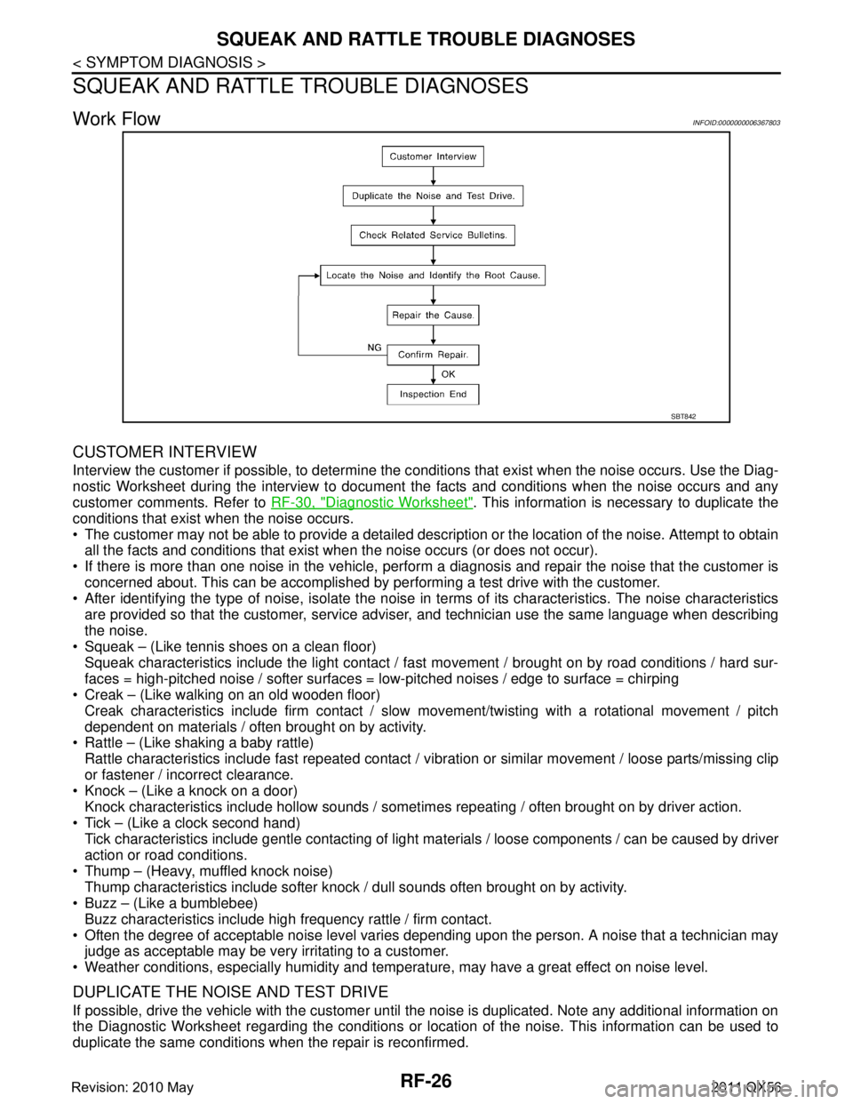
Work FlowINFOID:0000000006367803
CUSTOMER INTERVIEW
Interview the customer if possible, to determine the c onditions that exist when the noise occurs. Use the Diag-
nostic Worksheet during the interview to document the facts and conditions when the noise occurs and any
customer comments. Refer to RF-30, "
Diagnostic Worksheet". This information is necessary to duplicate the
conditions that exist when the noise occurs.
The customer may not be able to provide a detailed description or the location of the noise. Attempt to obtain all the facts and conditions that exist w hen the noise occurs (or does not occur).
If there is more than one noise in the vehicle, perform a diagnosis and repair the noise that the customer is
concerned about. This can be accomplished by per forming a test drive with the customer.
After identifying the type of noise, isolate the noise in terms of its characteristics. The noise characteristics
are provided so that the customer, service advis er, and technician use the same language when describing
the noise.
Squeak – (Like tennis shoes on a clean floor)
Squeak characteristics include the light contact / fast movement / brought on by road conditions / hard sur-
faces = high-pitched noise / softer surfaces = low-pitched noises / edge to surface = chirping
Creak – (Like walking on an old wooden floor)
Creak characteristics include firm contact / slow movement/twisting with a rotational movement / pitch
dependent on materials / often brought on by activity.
Rattle – (Like shaking a baby rattle)
Rattle characteristics include fast repeated contact / vibr ation or similar movement / loose parts/missing clip
or fastener / incorrect clearance.
Knock – (Like a knock on a door)
Knock characteristics include hollow sounds / someti mes repeating / often brought on by driver action.
Tick – (Like a clock second hand) Tick characteristics include gentle contacting of light materials / loose components / can be caused by driver
action or road conditions.
Thump – (Heavy, muffled knock noise) Thump characteristics include softer knock / dull sounds often brought on by activity.
Buzz – (Like a bumblebee)
Buzz characteristics include high frequency rattle / firm contact.
Often the degree of acceptable noise level varies depending upon the person. A noise that a technician may
judge as acceptable may be very irritating to a customer.
Weather conditions, especially humidity and temperat ure, may have a great effect on noise level.
DUPLICATE THE NOISE AND TEST DRIVE
If possible, drive the vehicle with the customer until the noise is duplicated. Note any additional information on
the Diagnostic Worksheet regarding the conditions or lo cation of the noise. This information can be used to
duplicate the same conditions when the repair is reconfirmed.
SBT842
Revision: 2010 May2011 QX56