2011 INFINITI QX56 lock
[x] Cancel search: lockPage 3916 of 5598
![INFINITI QX56 2011 Factory Service Manual
PCS
PUSH-BUTTON IGNITION SWITCH POSITION INDICATORPCS-75
< DTC/CIRCUIT DIAGNOSIS > [POWER DISTRIBUTION SYSTEM]
C
D
E
F
G H
I
J
K L
B A
O P
N
2. Check continuity between BCM harness connector
and pus INFINITI QX56 2011 Factory Service Manual
PCS
PUSH-BUTTON IGNITION SWITCH POSITION INDICATORPCS-75
< DTC/CIRCUIT DIAGNOSIS > [POWER DISTRIBUTION SYSTEM]
C
D
E
F
G H
I
J
K L
B A
O P
N
2. Check continuity between BCM harness connector
and pus](/manual-img/42/57033/w960_57033-3915.png)
PCS
PUSH-BUTTON IGNITION SWITCH POSITION INDICATORPCS-75
< DTC/CIRCUIT DIAGNOSIS > [POWER DISTRIBUTION SYSTEM]
C
D
E
F
G H
I
J
K L
B A
O P
N
2. Check continuity between BCM harness connector
and push-button ignition switch harness connector.
3. Check continuity between BCM harness connector and ground.
Is the inspection normal?
YES >> Replace push-button ignition switch.
NO >> Repair or replace harness.
Indicator BCM Push-button ignition switch
Continuity
Connector Terminal Connector Terminal
LOCK M71 91
M101 5
Existed
ACC 109 6
ON 73 7
Indicator BCM
GroundContinuity
Connector Terminal
LOCK M71 91
Not existed
ACC 109
ON 73
Revision: 2010 May2011 QX56
Page 3917 of 5598
![INFINITI QX56 2011 Factory Service Manual
PCS-76
< SYMPTOM DIAGNOSIS >[POWER DISTRIBUTION SYSTEM]
PUSH-BUTTON IGNITION SW
ITCH DOES NOT OPERATE
SYMPTOM DIAGNOSIS
PUSH-BUTTON IGNITION SWITCH DOES NOT OPERATE
DescriptionINFOID:0000000006220228 INFINITI QX56 2011 Factory Service Manual
PCS-76
< SYMPTOM DIAGNOSIS >[POWER DISTRIBUTION SYSTEM]
PUSH-BUTTON IGNITION SW
ITCH DOES NOT OPERATE
SYMPTOM DIAGNOSIS
PUSH-BUTTON IGNITION SWITCH DOES NOT OPERATE
DescriptionINFOID:0000000006220228](/manual-img/42/57033/w960_57033-3916.png)
PCS-76
< SYMPTOM DIAGNOSIS >[POWER DISTRIBUTION SYSTEM]
PUSH-BUTTON IGNITION SW
ITCH DOES NOT OPERATE
SYMPTOM DIAGNOSIS
PUSH-BUTTON IGNITION SWITCH DOES NOT OPERATE
DescriptionINFOID:0000000006220228
Check that vehicle is under the condition shown in “C onditions of vehicle” before starting diagnosis, and check
each symptom.
NOTE:
The engine start function, door lock function, power dist ribution system, and NATS-IVIS/NVIS in the Intelligent
Key system are closely related to each other regarding c ontrol. The vehicle security function can operate only
when the door lock and power distribution system are operating normally.
Conditions of Vehicle (Operating Conditions)
“ENGINE START BY I-KEY” in “WORK SUPPOR T” is ON when setting on CONSULT-III.
One or more of Intelligent Keys with registered Intelligent Key ID is in the vehicle.
Diagnosis ProcedureINFOID:0000000006220229
1.PERFORM WORK SUPPORT
Perform “INSIDE ANT DIAGNOSIS” on Wo rk Support of “INTELLIGENT KEY”.
Refer to DLK-41, "
INTELLIGENT KEY : CONSULT-III Function (BCM - INTELLIGENT KEY)".
>> GO TO 2.
2.PERFORM SELF-DIAGNOSIS RESULT
Perform Self-Diagnosis Result of “BCM”.
Is DTC detected?
YES >> Refer to BCS-57, "DTCIndex".
NO >> GO TO 3.
3.CHECK PUSH-BUTTON IGNITION SWITCH
Check push-button ignition switch.
Refer to PCS-71, "
ComponentFunctionCheck".
Is the operation normal?
YES >> GO TO 4.
NO >> Repair or replace malfunctioning parts.
4.CONFIRM THE OPERATION
Confirm the operation again.
Is the inspection normal?
YES >> Check intermittent incident. Refer to GI-40, "Intermittent Incident".
NO >> GO TO 1.
Revision: 2010 May2011 QX56
Page 3920 of 5598

PG
PG-1
ELECTRICAL & POWER CONTROL
C
DE
F
G H
I
J
K L
B
SECTION PG
A
O P
N
CONTENTS
POWER SUPPLY, GROUND & CIRCUIT ELEMENTS
PRECAUTION ................
...............................3
PRECAUTIONS .............................................. .....3
Precaution for Supplemental Restraint System
(SRS) "AIR BAG" and "SEAT BELT PRE-TEN-
SIONER" ............................................................. ......
3
PREPARATION ............................................4
PREPARATION .............................................. .....4
Special Service Tools .......................................... ......4
SYSTEM DESCRIPTION ..............................5
COMPONENT PARTS ................................... .....5
Circuit Breaker .................................................... ......5
Battery .......................................................................5
Harness Connector ...................................................5
Standardized Relay ...................................................8
WIRING DIAGRAM ......................................11
POWER SUPPLY ROUTING CIRCUIT .......... ....11
Wiring Diagram - BATTERY POWER SUPPLY - ....11
Wiring Diagram - BATTERY POWER SUPPLY
FUSIBLE LINK No. K - ........................................ ....
29
Wiring Diagram - BATTERY POWER SUPPLY
FUSIBLE LINK No. S - ............................................
33
Wiring Diagram - BATTERY POWER SUPPLY
FUSE No. 6 - ...........................................................
37
Wiring Diagram - BATTERY POWER SUPPLY
FUSE No. 7 - ...........................................................
43
Wiring Diagram - BATTERY POWER SUPPLY
FUSE No. 9 - ...........................................................
46
Wiring Diagram - BATTERY POWER SUPPLY
FUSE No. 10 - .........................................................
51
Wiring Diagram - BATTERY POWER SUPPLY
FUSE No. 35 - .........................................................
54
Wiring Diagram - BATTERY POWER SUPPLY
FUSE No. 43 - .........................................................
60
Wiring Diagram - BATTERY POWER SUPPLY
FUSE No. 46 - .........................................................
64
Wiring Diagram - BATTERY POWER SUPPLY
FUSE No. 47 - ..................................................... ....
67
Wiring Diagram - ACCESSORY POWER SUP-
PLY - ........................................................................
80
Wiring Diagram - ACCESSORY POWER SUP-
PLY FUSE No. 19 - .................................................
83
Wiring Diagram - ACCESSORY POWER SUP-
PLY FUSE No. 20 - .................................................
86
Wiring Diagram - IGNITION POWER SUPPLY - . ....89
Wiring Diagram - IGNITION POWER SUPPLY
FUSE No. 3 - ....................................................... ..
105
Wiring Diagram - IGNITION POWER SUPPLY
FUSE No. 4 - ....................................................... ..
109
Wiring Diagram - IGNITION POWER SUPPLY
FUSE No. 37 - ..................................................... ..
115
Wiring Diagram - IGNITION POWER SUPPLY
FUSE No. 55 - ..................................................... ..
121
Wiring Diagram - IGNITION POWER SUPPLY
FUSE No. 57 - ..................................................... ..
123
Wiring Diagram - IGNITION POWER SUPPLY
FUSE No. 61 - ..................................................... ..
126
Wiring Diagram - IGNITION POWER SUPPLY
FUSE No. 80 - ..................................................... ..
129
OPTION HARNESS ........................................133
Wiring Diagram .................................................... ..133
FUSE BLOCK - JUNCTION BOX (J/B) ..........140
Fuse, Connector and Terminal Arrangement ........140
FUSE, FUSIBLE LINK AND RELAY BOX ......141
Fuse and Fusible Link Arrangement ......................141
IPDM E/R (INTELLIGENT POWER DISTRI-
BUTION MODULE ENGINE ROOM) ..............
143
Fuse, Connector and Terminal Arrangement ........143
HARNESS LAYOUT .......................................144
How To Read Harness Layout ............................ ..144
Outline ...................................................................145
Engine Room Harness ..........................................146
Engine Control Harness ........................................148
Revision: 2010 May2011 QX56
Page 3924 of 5598

PG
COMPONENT PARTSPG-5
< SYSTEM DESCRIPTION >
C
DE
F
G H
I
J
K L
B A
O P
N
SYSTEM DESCRIPTION
COMPONENT PARTS
Circuit BreakerINFOID:0000000006275745
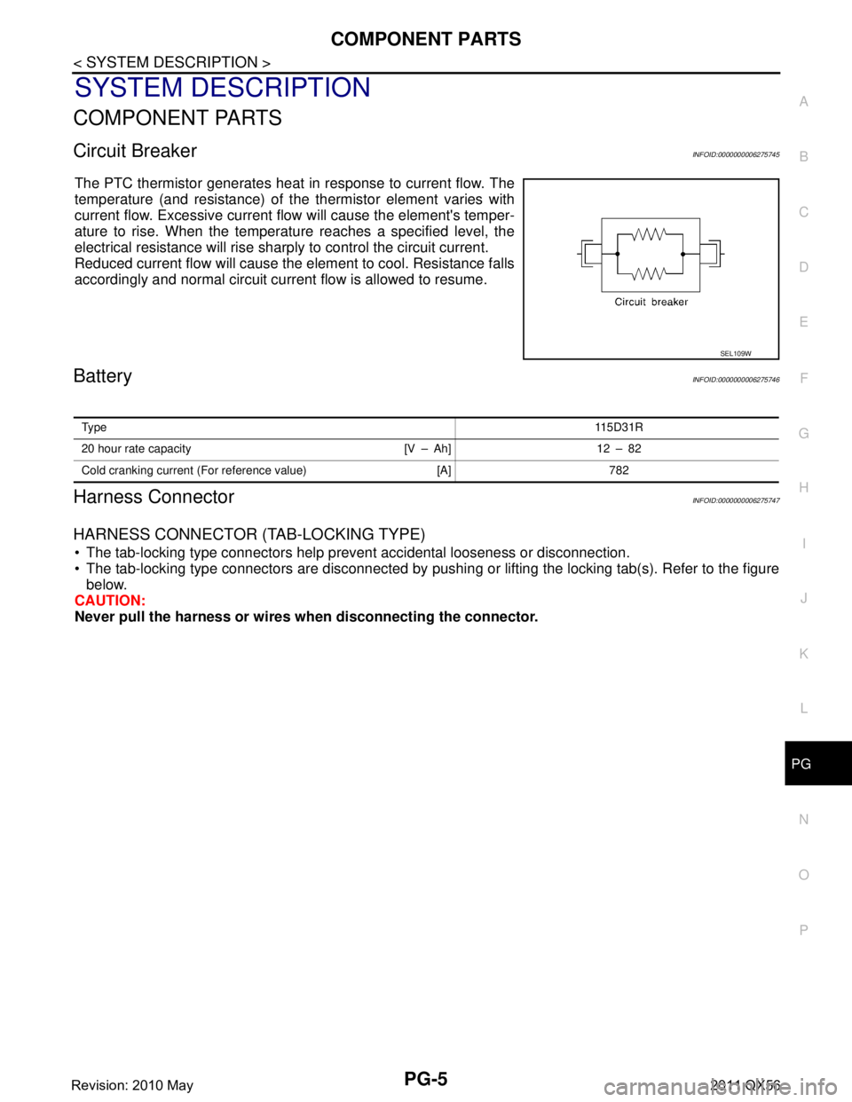
The PTC thermistor generates heat in response to current flow. The
temperature (and resistance) of t
he thermistor element varies with
current flow. Excessive current flow will cause the element's temper-
ature to rise. When the temperature reaches a specified level, the
electrical resistance will rise shar ply to control the circuit current.
Reduced current flow will cause the element to cool. Resistance falls
accordingly and normal circuit current flow is allowed to resume.
BatteryINFOID:0000000006275746
Harness ConnectorINFOID:0000000006275747
HARNESS CONNECTOR (TAB-LOCKING TYPE)
The tab-locking type connectors help prevent accidental looseness or disconnection.
The tab-locking type connectors are disconnected by pushi ng or lifting the locking tab(s). Refer to the figure
below.
CAUTION:
Never pull the harness or wires when disconnecting the connector.
SEL109W
Ty pe 115D31R
20 hour rate capacity [V – Ah] 12 – 82
Cold cranking current (For reference value) [A] 782
Revision: 2010 May2011 QX56
Page 3925 of 5598
![INFINITI QX56 2011 Factory Service Manual
PG-6
< SYSTEM DESCRIPTION >
COMPONENT PARTS
[Example]
HARNESS CONNECTOR (SLIDE-LOCKING TYPE)
A new style slide-locking type connector is used on certain systems and components, especially those
rel INFINITI QX56 2011 Factory Service Manual
PG-6
< SYSTEM DESCRIPTION >
COMPONENT PARTS
[Example]
HARNESS CONNECTOR (SLIDE-LOCKING TYPE)
A new style slide-locking type connector is used on certain systems and components, especially those
rel](/manual-img/42/57033/w960_57033-3924.png)
PG-6
< SYSTEM DESCRIPTION >
COMPONENT PARTS
[Example]
HARNESS CONNECTOR (SLIDE-LOCKING TYPE)
A new style slide-locking type connector is used on certain systems and components, especially those
related to OBD.
The slide-locking type connectors help prevent incomplete locking and accidental looseness or disconnec-
tion.
The slide-locking type connectors are disconnected by pushing or pulling the slider. Refer to the figure below.
CAUTION:
Never pull the harness or wires when disconnecting the connector.
Be careful not to damage the connector su pport bracket when disconnecting the connector.
SEL769DA
Revision: 2010 May2011 QX56
Page 3926 of 5598
![INFINITI QX56 2011 Factory Service Manual
PG
COMPONENT PARTSPG-7
< SYSTEM DESCRIPTION >
C
DE
F
G H
I
J
K L
B A
O P
N
[Example]
HARNESS CONNECTOR (LEVER LOCKING TYPE)
Lever locking type harness connectors are used on cert
ain control units INFINITI QX56 2011 Factory Service Manual
PG
COMPONENT PARTSPG-7
< SYSTEM DESCRIPTION >
C
DE
F
G H
I
J
K L
B A
O P
N
[Example]
HARNESS CONNECTOR (LEVER LOCKING TYPE)
Lever locking type harness connectors are used on cert
ain control units](/manual-img/42/57033/w960_57033-3925.png)
PG
COMPONENT PARTSPG-7
< SYSTEM DESCRIPTION >
C
DE
F
G H
I
J
K L
B A
O P
N
[Example]
HARNESS CONNECTOR (LEVER LOCKING TYPE)
Lever locking type harness connectors are used on cert
ain control units and control modules such as ECM,
ABS actuator and electric unit (control unit), etc.
Lever locking type harness connectors are also us ed on super multiple junction (SMJ) connectors.
Always confirm the lever is fully locked in place by mo ving the lever as far as it will go to ensure full connec-
tion.
CAUTION:
SEL769V
Revision: 2010 May2011 QX56
Page 4059 of 5598

PG-140
< WIRING DIAGRAM >
FUSE BLOCK - JUNCTION BOX (J/B)
FUSE BLOCK - JUNCTION BOX (J/B)
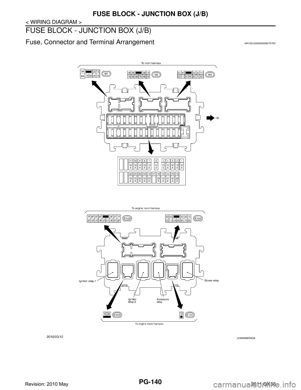
Fuse, Connector and Terminal ArrangementINFOID:0000000006275753
JCMWM8094GB
Revision: 2010 May2011 QX56
Page 4088 of 5598

PWC-3
C
DE
F
G H
I
J
L
M A
B
PWC
N
O P
WHEN BOTH POWER WINDOW MAIN SWITCH
AND REAR POWER WINDOW SWITCH LH ARE
OPERATED ...........................................................
....
64
WHEN BOTH POWER WINDOW MAIN SWITCH
AND REAR POWER WINDOW SWITCH LH ARE
OPERATED : Diagnosis Procedure ........................
64
REAR RH SIDE POWER WINDOW ALONE
DOES NOT OPERATE .......................................
65
WHEN POWER WINDOW MAIN SWITCH IS OP-
ERATED ................................................................ ....
65
WHEN POWER WINDOW MAIN SWITCH IS OP-
ERATED : Diagnosis Procedure .............................
65
WHEN REAR POWER WINDOW SWITCH RH IS
OPERATED ........................................................... ....
65
WHEN REAR POWER WINDOW SWITCH RH IS
OPERATED : Diagnosis Procedure ........................
65
WHEN BOTH POWER WINDOW MAIN SWITCH
AND REAR POWER WINDOW SWITCH RH ARE
OPERATED ........................................................... ....
65
WHEN BOTH POWER WINDOW MAIN SWITCH
AND REAR POWER WINDOW SWITCH RH ARE
OPERATED : Diagnosis Procedure ........................
65
AUTO OPERATION DOES NOT OPERATE
BUT MANUAL OPERATE NORMALLY ............
66
DRIVER SIDE ........................................................ ....66
DRIVER SIDE : Diagnosis Procedure .....................66
PASSENGER SIDE ...................................................66
PASSENGER SIDE : Diagnosis Procedure ........ ....66
REAR LH ............................................................... ....66
REAR LH : Diagnosis Procedure ............................66
REAR RH ............................................................... ....67
REAR RH : Diagnosis Procedure ............................67
ANTI-PINCH FUNCTION DOES NOT OPER-
ATE ....................................................................
68
Diagnosis Procedure ........................................... ....68
POWER WINDOW RETAINED POWER
FUNCTION DOES NOT OPERATE NORMAL-
LY ......................................................................
69
Diagnosis Procedure ...............................................69
DOOR KEY CYLINDER SWITCH DOES NOT
OPERATE POWER WINDOWS ........................
70
Diagnosis Procedure ...............................................70
KEYLESS POWER WINDOW DOWN DOES
NOT OPERATE .................................................
71
Diagnosis Procedure ...............................................71
POWER WINDOW LOCK SWITCH DOES
NOT FUNCTION ................................................
72
Diagnosis Procedure ...............................................72
POWER WINDOW SWITCH DOES NOT IL-
LUMINATE ........................................................
73
DRIVER SIDE ......................................................... ....73
DRIVER SIDE : Diagnosis Procedure .....................73
PASSENGER SIDE ....................................................73
PASSENGER SIDE : Diagnosis Procedure ........ ....73
REAR LH ................................................................ ....73
REAR LH : Diagnosis Procedure .............................73
REAR RH ............................................................... ....73
REAR RH : Diagnosis Procedure ............................73
REMOVAL AND INSTALLATION ...............74
POWER WINDOW MAIN SWITCH ...................74
Removal and Installation ..................................... ....74
Revision: 2010 May2011 QX56