Page 4758 of 5598
![INFINITI QX56 2011 Factory Service Manual
VEHICLE SECURITY SYSTEM CANNOT BE SET
SEC-151
< SYMPTOM DIAGNOSIS > [WITH INTELLIGENT KEY SYSTEM]
C
D
E
F
G H
I
J
L
M A
B
SEC
N
O P
VEHICLE SECURITY S YSTEM CANNOT BE SET
INTELLIGENT KEY
INTELLIGENT INFINITI QX56 2011 Factory Service Manual
VEHICLE SECURITY SYSTEM CANNOT BE SET
SEC-151
< SYMPTOM DIAGNOSIS > [WITH INTELLIGENT KEY SYSTEM]
C
D
E
F
G H
I
J
L
M A
B
SEC
N
O P
VEHICLE SECURITY S YSTEM CANNOT BE SET
INTELLIGENT KEY
INTELLIGENT](/manual-img/42/57033/w960_57033-4757.png)
VEHICLE SECURITY SYSTEM CANNOT BE SET
SEC-151
< SYMPTOM DIAGNOSIS > [WITH INTELLIGENT KEY SYSTEM]
C
D
E
F
G H
I
J
L
M A
B
SEC
N
O P
VEHICLE SECURITY S YSTEM CANNOT BE SET
INTELLIGENT KEY
INTELLIGENT KEY : DescriptionINFOID:0000000006226329
Armed phase is not activated when door is locked using Intelligent Key.
NOTE:
Check that vehicle is under the condition shown in “C onditions of vehicle” before starting diagnosis, and check
each symptom.
CONDITION OF VEHICLE (OPERATING CONDITION)
Confirm the setting of “SECUTIRY ALARM SET” is ON in “WORK SUPPORT” mode of “THEFT ALM” of
“BCM” using CONSULT-III.
INTELLIGENT KEY : Diagnosis ProcedureINFOID:0000000006226330
1.CHECK INTELLIGENT KEY SYSTEM (REMOTE KEYLESS ENTRY FUNCTION)
Lock/unlock door with Intelligent Key.
Refer to DLK-19, "
DOOR LOCK FUNCTION : System Description".
Is the inspection result normal?
YES >> GO TO 2.
NO >> Check Intelligent Key system (remote keyless entry function). Refer to DLK-175, "
Diagnosis Pro-
cedure".
2.CHECK HOOD SWITCH
Check hood swiwtch.
Refer to SEC-141, "
ComponentFunctionCheck".
Is the inspection result normal?
YES >> GO TO 3.
NO >> Repair or replace hood switch.
3.CONFIRM THE OPERATION
Confirm the operation again.
Is the result normal?
YES >> Check intermittent incident. Refer to GI-40, "Intermittent Incident".
NO >> GO TO 1.
DOOR REQUEST SWITCH
DOOR REQUEST SWITCH : DescriptionINFOID:0000000006226331
Armed phase is not activated when door is locked using door request switch.
NOTE:
Check that vehicle is under the condition shown in “C onditions of vehicle” before starting diagnosis, and check
each symptom.
CONDITION OF VEHICLE (OPERATING CONDITION)
Confirm the setting of “SECURITY ALARM SET” is ON in “WORK SUPPORT” mode of “THEFT ALM” of
“BCM” using CONSULT-III.
DOOR REQUEST SWITCH : Diagnosis ProcedureINFOID:0000000006226332
1.CHECK INTELLIGENT KEY SYS TEM (DOOR LOCK FUNCTION)
Lock/unlock door with door request switch.
Refer to DLK-19, "
DOOR LOCK FUNCTION : System Description".
Is the inspection result normal?
YES >> GO TO 2.
NO >> Check Intelligent Key system (door lock function). Refer to DLK-172, "
ALL DOOR REQUEST
SWITCHES : Diagnosis Procedure".
Revision: 2010 May2011 QX56
Page 4759 of 5598
![INFINITI QX56 2011 Factory Service Manual
SEC-152
< SYMPTOM DIAGNOSIS >[WITH INTELLIGENT KEY SYSTEM]
VEHICLE SECURITY SYSTEM CANNOT BE SET
2.CHECK HOOD SWITCH
Check hood swiwtch.
Refer to SEC-141, "
ComponentFunctionCheck".
Is the inspectio INFINITI QX56 2011 Factory Service Manual
SEC-152
< SYMPTOM DIAGNOSIS >[WITH INTELLIGENT KEY SYSTEM]
VEHICLE SECURITY SYSTEM CANNOT BE SET
2.CHECK HOOD SWITCH
Check hood swiwtch.
Refer to SEC-141, "
ComponentFunctionCheck".
Is the inspectio](/manual-img/42/57033/w960_57033-4758.png)
SEC-152
< SYMPTOM DIAGNOSIS >[WITH INTELLIGENT KEY SYSTEM]
VEHICLE SECURITY SYSTEM CANNOT BE SET
2.CHECK HOOD SWITCH
Check hood swiwtch.
Refer to SEC-141, "
ComponentFunctionCheck".
Is the inspection result normal?
YES >> GO TO 3.
NO >> Repair or replace hood switch.
3.CONFIRM THE OPERATION
Confirm the operation again.
Is the result normal?
YES >> Check intermittent incident. Refer to GI-40, "Intermittent Incident".
NO >> GO TO 1.
DOOR KEY CYLINDER
DOOR KEY CYLINDER : DescriptionINFOID:0000000006375072
Armed phase is not activated when door is locked using mechanical key.
NOTE:
Check that vehicle is under the condition shown in “C onditions of vehicle” before starting diagnosis, and check
each symptom.
CONDITION OF VEHICLE (OPERATING CONDITION)
Confirm the setting of “SECURITY ALARM SET” is ON in “WORK SUPPORT” mode of “THEFT ALM” of
“BCM” using CONSULT-III.
DOOR KEY CYLINDER : Diagnosis ProcedureINFOID:0000000006375073
1.CHECK POWER DOOR LOCK SYSTEM
Lock/unlock door with mechanical key.
Refer to DLK-16, "
System Description".
Is the inspection result normal?
YES >> GO TO 2.
NO >> Check power door lock system. Refer to DLK-171, "
Diagnosis Procedure".
2.CONFIRM THE OPERATION
Confirm the operation again.
Is the result normal?
YES >> Check intermittent incident. Refer to GI-40, "Intermittent Incident".
NO >> GO TO 1.
Revision: 2010 May2011 QX56
Page 4760 of 5598
![INFINITI QX56 2011 Factory Service Manual
VEHICLE SECURITY ALARM DOES NOT ACTIVATE
SEC-153
< SYMPTOM DIAGNOSIS > [WITH INTELLIGENT KEY SYSTEM]
C
D
E
F
G H
I
J
L
M A
B
SEC
N
O P
VEHICLE SECURITY ALAR M DOES NOT ACTIVATE
DescriptionINFOID:0000 INFINITI QX56 2011 Factory Service Manual
VEHICLE SECURITY ALARM DOES NOT ACTIVATE
SEC-153
< SYMPTOM DIAGNOSIS > [WITH INTELLIGENT KEY SYSTEM]
C
D
E
F
G H
I
J
L
M A
B
SEC
N
O P
VEHICLE SECURITY ALAR M DOES NOT ACTIVATE
DescriptionINFOID:0000](/manual-img/42/57033/w960_57033-4759.png)
VEHICLE SECURITY ALARM DOES NOT ACTIVATE
SEC-153
< SYMPTOM DIAGNOSIS > [WITH INTELLIGENT KEY SYSTEM]
C
D
E
F
G H
I
J
L
M A
B
SEC
N
O P
VEHICLE SECURITY ALAR M DOES NOT ACTIVATE
DescriptionINFOID:0000000006226333
Alarm does not operate when alarm operating condition is satisfied.
NOTE:
Check that vehicle is under the condition shown in “C onditions of vehicle” before starting diagnosis, and check
each symptom.
CONDITIONS OF VEHICLE (OPERATING CONDITIONS)
Confirm the setting of “SECURITY ALARM SET” is ON in “WORK SUPPORT” mode of “THEFT ALM” of
“BCM” using CONSULT-III.
Diagnosis ProcedureINFOID:0000000006226334
1.CHECK DOOR SWITCH
Check door switch.
Refer to DLK-117, "
ComponentFunctionCheck".
Is the inspection result normal?
YES >> GO TO 2.
NO >> Replace the malfunctioning door switch
2.CHECK HOOD SWITCH
Check hood swiwtch.
Refer to SEC-141, "
ComponentFunctionCheck".
Is the inspection result normal?
YES >> GO TO 3.
NO >> Repair or replace hood switch.
3.CHECK HORN FUNCTION
Check horn function.
Refer to SEC-143, "
ComponentFunctionCheck".
Is the inspection result normal?
YES >> GO TO 4.
NO >> Repair or replace the malfunctioning parts.
4.CHECK HEADLAMP FUNCTION
Check headlamp function.
Refer to SEC-140, "
Component Function Check".
Is the inspection result normal?
YES >> GO TO 5.
NO >> Repair or replace the malfunctioning parts.
5.CONFIRM THE OPERATION
Confirm the operation again.
Is the result normal?
YES >> Check intermittent incident. Refer to GI-40, "Intermittent Incident".
NO >> GO TO 1.
Revision: 2010 May2011 QX56
Page 4761 of 5598
![INFINITI QX56 2011 Factory Service Manual
SEC-154
< SYMPTOM DIAGNOSIS >[WITH INTELLIGENT KEY SYSTEM]
PANIC ALARM FUNCTION DOES NOT OPERATE
PANIC ALARM FUNCTION
DOES NOT OPERATE
DescriptionINFOID:0000000006226336
NOTE:
Before performing th INFINITI QX56 2011 Factory Service Manual
SEC-154
< SYMPTOM DIAGNOSIS >[WITH INTELLIGENT KEY SYSTEM]
PANIC ALARM FUNCTION DOES NOT OPERATE
PANIC ALARM FUNCTION
DOES NOT OPERATE
DescriptionINFOID:0000000006226336
NOTE:
Before performing th](/manual-img/42/57033/w960_57033-4760.png)
SEC-154
< SYMPTOM DIAGNOSIS >[WITH INTELLIGENT KEY SYSTEM]
PANIC ALARM FUNCTION DOES NOT OPERATE
PANIC ALARM FUNCTION
DOES NOT OPERATE
DescriptionINFOID:0000000006226336
NOTE:
Before performing the diagnosis following procedure, check “Work Flow”. Refer to SEC-48, "
Work Flow".
Check that vehicle is under the condition shown in “Conditions of vehicle” before starting diagnosis, and
check each symptom.
CONDITIONS OF VEHICLE (OPERATION CONDITIONS)
Ignition switch is in OFF or LOCK position.
Intelligent Key is removed from key slot.
Diagnosis ProcedureINFOID:0000000006226337
1.CHECK REMOTE KEYL ESS ENTRY FUNCTION
Check remote keyless entry function.
Does door lock/unlock with Intelligent key button?
YES >> GO TO 2.
NO >> Go to DLK-175, "
Diagnosis Procedure".
2.CHECK VEHICLE SECURITY ALARM OPERATION
Check vehicle security alarm operation.
Does alarm (headlamps and horns) active?
YES >> GO TO 3.
NO >> Go to SEC-18, "
VEHICLE SECURITY SYSTEM : System Description".
3.CHECK “PANIC ALARM SET” SETTING IN “WORK SUPPORT”
Check “PANIC ALARM SET” setting in “WORK SUPPORT”.
Refer to SEC-22, "
INTELLIGENT KEY : CONSULT-III F unction (BCM - INTELLIGENT KEY)".
Is the inspection result normal?
YES >> GO TO 4.
NO >> Set “PANIC ALARM SET” setting in “WORK SUPPORT”.
4.CONFIRM THE OPERATION
Confirm the operation again.
Is the result normal?
YES >> Check intermittent incident. Refer to GI-40, "Intermittent Incident".
NO >> GO TO 1.
Revision: 2010 May2011 QX56
Page 4775 of 5598

SR-12
< REMOVAL AND INSTALLATION >
DRIVER AIR BAG MODULE
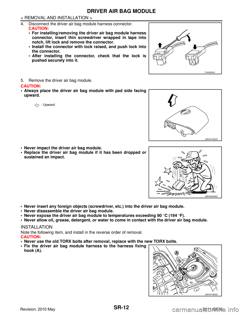
4. Disconnect the driver air bag module harness connector.CAUTION:
For installing/removing the driver air bag module harnessconnector, insert thin screwdriver wrapped in tape into
notch, lift lock and remove the connector.
Install the connector with lock raised, and push lock into
the connector.
After installing the conn ector, check that the lock is
pushed securely into it.
5. Remove the driver air bag module.
CAUTION:
Always place the driver air bag module with pad side facing upward.
Never impact the driver air bag module.
Replace the driver air bag modu le if it has been dropped or
sustained an impact.
Never insert any foreign objects (screwdriver , etc.) into the driver air bag module.
Never disassemble the driver air bag module.
Never expose the driver air bag module to temperatures exceeding 90 °C (194 °F).
Never allow oil, grease, detergent, or water to come in contact with the driver air bag module.
INSTALLATION
Note the following item, and install in the reverse order of removal.
CAUTION:
Never use the old TORX bolts after removal, replace with the new TORX bolts.
Fix the driver air bag module harness to the harness fixing hook (A).
PHIA0953J
: Upward
JMHIA1502ZZ
JMHIA0009ZZ
JMHIA1485ZZ
Revision: 2010 May2011 QX56
Page 4776 of 5598
DRIVER AIR BAG MODULESR-13
< REMOVAL AND INSTALLATION >
C
DE
F
G
I
J
K L
M A
B
SR
N
O P
Tighten the TORX bolts after comp letely adjusting the centers of fixing holes on the driver air bag
module side and the steer ing wheel side. If the holes are misali gned, the bolt threads are damaged
and the module is not installed securely.
Never damage the harness while installing.
If malfunction is detected by the air bag warnin g lamp, after repair or replacement of the malfunc-
tioning parts, reset the memory using sel f-diagnosis or CONSULT-III. Refer to SRC-14, "
On Board
Diagnosis Function" or SRC-19, "CONSULT-III Function".
After the work is completed, check that no system malfunction is detected by air bag warning lamp.
Revision: 2010 May2011 QX56
Page 4783 of 5598

SR-20
< REMOVAL AND INSTALLATION >
SIDE CURTAIN AIR BAG MODULE
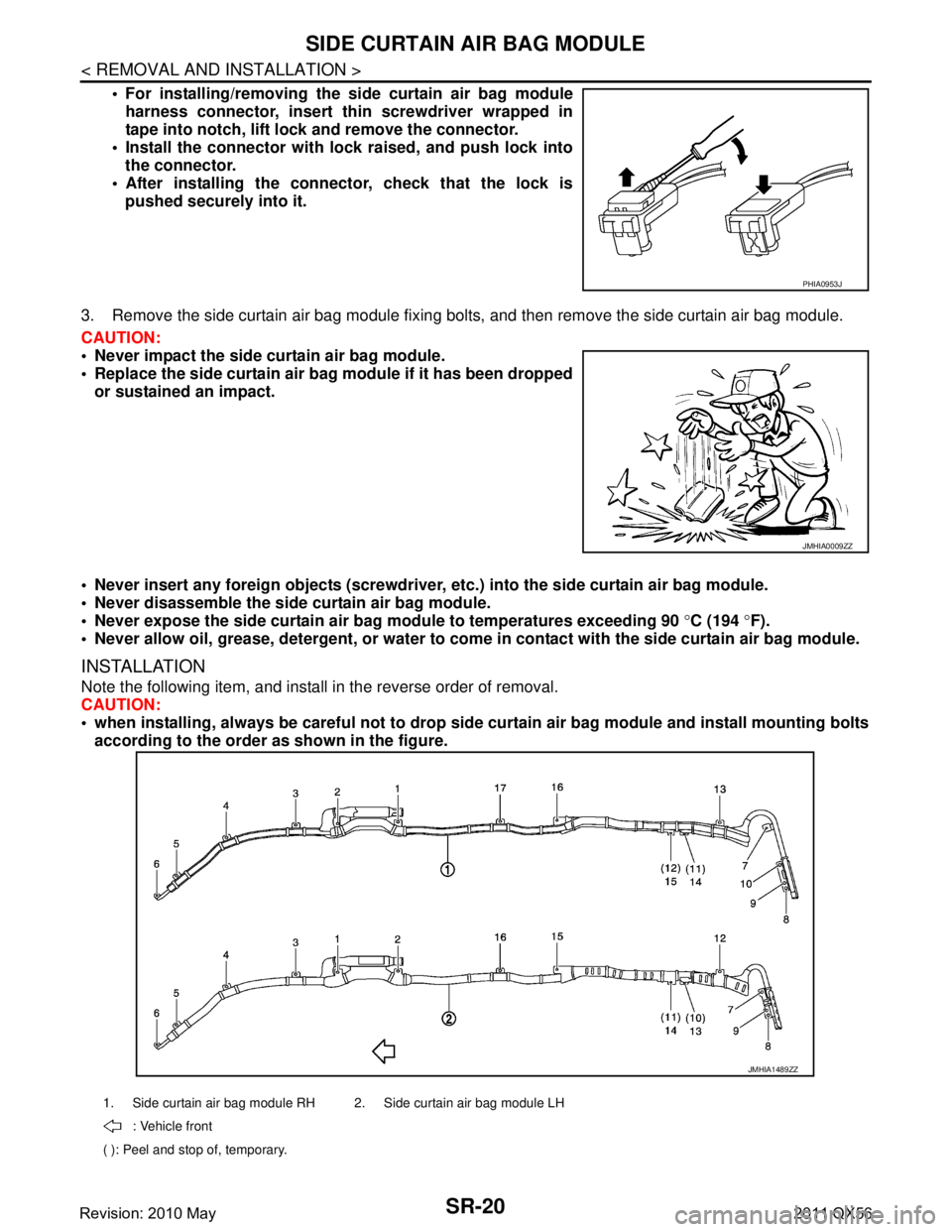
For installing/removing the side curtain air bag moduleharness connector, insert thin screwdriver wrapped in
tape into notch, lift lock and remove the connector.
Install the connector with lock raised, and push lock into
the connector.
After installing the conn ector, check that the lock is
pushed securely into it.
3. Remove the side curtain air bag module fixing bolts, and then remove the side curtain air bag module.
CAUTION:
Never impact the side curtain air bag module.
Replace the side curtain air bag module if it has been dropped
or sustained an impact.
Never insert any foreign objects (screwdriver, etc.) into the side curtain air bag module.
Never disassemble the side curtain air bag module.
Never expose the side curtain air ba g module to temperatures exceeding 90 °C (194 °F).
Never allow oil, grease, detergent, or water to come in contact with the side curtain air bag module.
INSTALLATION
Note the following item, and install in the reverse order of removal.
CAUTION:
when installing, always be careful not to drop side curtain air bag module and install mounting bolts
according to the order as shown in the figure.
PHIA0953J
JMHIA0009ZZ
1. Side curtain air bag module RH 2. Side curtain air bag module LH
: Vehicle front
( ): Peel and stop of, temporary.
JMHIA1489ZZ
Revision: 2010 May2011 QX56
Page 4790 of 5598

DIAGNOSIS SENSOR UNITSR-27
< REMOVAL AND INSTALLATION >
C
DE
F
G
I
J
K L
M A
B
SR
N
O P
CAUTION:
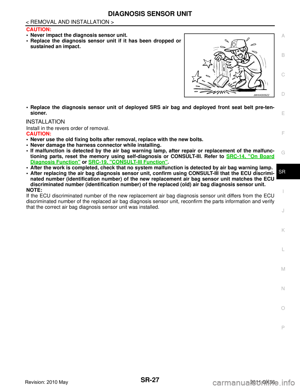
Never impact the diagnosis sensor unit.
Replace the diagnosis sensor uni t if it has been dropped or
sustained an impact.
Replace the diagnosis sensor unit of deployed SRS air bag and deployed front seat belt pre-ten-
sioner.
INSTALLATION
Install in the revers order of removal.
CAUTION:
Never use the old fixing bolts afte r removal, replace with the new bolts.
Never damage the harness co nnector while installing.
If malfunction is detected by the air bag warnin g lamp, after repair or replacement of the malfunc-
tioning parts, reset the memory using sel f-diagnosis or CONSULT-III. Refer to SRC-14, "
On Board
Diagnosis Function" or SRC-19, "CONSULT-III Function".
After the work is completed, check that no system malfunction is detected by air bag warning lamp.
After replacing the air bag diag nosis sensor unit, confirm using CO NSULT-III that the ECU discrimi-
nated number (identification nu mber) of the new replacement air bag sensor unit matches the ECU
discriminated number (identification number) of the replaced (old) air bag diagnosis sensor unit.
NOTE:
If the ECU discriminated number of the new replacement air bag diagnosis sensor unit differs from the ECU
discriminated number of the replaced air bag diagnosis sens or unit, reconfirm the parts information and verify
that the correct air bag diagnosis sensor unit was installed.
JMHIA0009ZZ
Revision: 2010 May2011 QX56