2011 INFINITI QX56 windshield
[x] Cancel search: windshieldPage 4408 of 5598

SCS-48
< PRECAUTION >[AIR LEVELIZER CONTROL SYSTEM]
PRECAUTIONS
5. When the repair work is completed, re-connect bot
h battery cables. With the brake pedal released, turn
the push-button ignition switch from ACC position to ON position, then to LOCK position. (The steering
wheel will lock when the push-button igniti on switch is turned to LOCK position.)
6. Perform self-diagnosis check of all control units using CONSULT-III.
Precaution for Procedure without Cowl Top CoverINFOID:0000000006256139
When performing the procedure after removing cowl top cover, cover
the lower end of windshield with urethane, etc.
Precaution for Air Levelizer Control SystemINFOID:0000000006256038
Never allow water and dust to enter the inside of air compressor.
Never disassemble the vehicle height sensor.
PIIB3706J
Revision: 2010 May2011 QX56
Page 4560 of 5598
SQUEAK AND RATTLE TROUBLE DIAGNOSESSE-101
< SYMPTOM DIAGNOSIS >
C
DE
F
G H
I
K L
M A
B
SE
N
O P
Insulates where slight movement is present. Ideal for instrument panel applications.
SILICONE GREASE
Used in place of UHMW tape that is be visible or does not fit. Will only last a few months.
SILICONE SPRAY
Used when grease cannot be applied.
DUCT TAPE
Used to eliminate movement.
CONFIRM THE REPAIR
Confirm that the cause of a noise is repaired by test driving the vehicle. Operate the vehicle under the same
conditions as when the noise originally occurred. Refer to the notes on the Diagnostic Worksheet.
Inspection ProcedureINFOID:0000000006219939
Refer to Table of Contents for specific component removal and installation information.
INSTRUMENT PANEL
Most incidents are caused by contact and movement between:
1. The cluster lid A and instrument panel
2. Acrylic lens and combination meter housing
3. Instrument panel to front pillar garnish
4. Instrument panel to windshield
5. Instrument panel mounting pins
6. Wiring harnesses behind the combination meter
7. A/C defroster duct and duct joint
These incidents can usually be located by tapping or moving the components to duplicate the noise or by
pressing on the components while driving to stop the noise. Most of these incidents can be repaired by
applying felt cloth tape or silicon spray (in hard to reach areas). Urethane pads can be used to insulate
wiring harness.
CAUTION:
Never use silicone spray to isolate a squeak or ra ttle. If the area is saturated with silicone, the
recheck of repair becomes impossible.
CENTER CONSOLE
Components to pay attention to include:
1. Shifter assembly cover to finisher
2. A/C control unit and cluster lid C
3. Wiring harnesses behind audio and A/C control unit
The instrument panel repair and isolation pr ocedures also apply to the center console.
DOORS
Pay attention to the following:
1. Finisher and inner panel making a slapping noise
2. Inside handle escutcheon to door finisher
3. Wiring harnesses tapping
4. Door striker out of alignment causing a popping noise on starts and stops
Tapping or moving the components or pressing on them while driving to duplicate the conditions can isolate
many of these incidents. The areas can usually be insula ted with felt cloth tape or insulator foam blocks from
the Nissan Squeak and Rattle Kit (J-43980) to repair the noise.
TRUNK
Trunk noises are often caused by a loose jack or loose items put into the trunk by the customer.
In addition look for the following:
1. Trunk lid dumpers out of adjustment
2. Trunk lid striker out of adjustment
3. The trunk lid torsion bars knocking together
4. A loose license plate or bracket
Revision: 2010 May2011 QX56
Page 4561 of 5598
SE-102
< SYMPTOM DIAGNOSIS >
SQUEAK AND RATTLE TROUBLE DIAGNOSES
Most of these incidents can be repaired by adjusting, securing or insulating the item(s) or component(s) caus-
ing the noise.
SUNROOF/HEADLINING
Noises in the sunroof/headlining area c an often be traced to one of the following:
1. Sunroof lid, rail, linkage or seals making a rattle or light knocking noise
2. Sunvisor shaft shaking in the holder
3. Front or rear windshield touching headlining and squeaking
Again, pressing on the components to stop the noise while duplicating the conditions can isolate most of these
incidents. Repairs usually consist of insulating with felt cloth tape.
SEATS
When isolating seat noise it's important to note the position the seats in and the load placed on the seat when
the noise occurs. These conditions should be duplicated when verifying and isolating the cause of the noise.
Cause of seat noise include:
1. Headrest rods and holder
2. A squeak between the seat pad cushion and frame
3. The rear seatback lock and bracket
These noises can be isolated by moving or pressing on the suspected components while duplicating the con-
ditions under which the noise occurs.Most of these incidents can be repaired by repositioning the component
or applying urethane tape to the contact area.
UNDERHOOD
Some interior noise may be caused by components under the hood or on the engine wall. The noise is then
transmitted into the passenger compartment.
Causes of transmitted underhood noise include:
1. Any component mounted to the engine wall
2. Components that pass through the engine wall
3. Engine wall mounts and connectors
4. Loose radiator mounting pins
5. Hood bumpers out of adjustment
6. Hood striker out of adjustment
These noises can be difficult to isolate since they cannot be reached from the interior of the vehicle. The best
method is to secure, move or insulate one component at a time and test drive the \
vehicle. Also, engine RPM
or load can be changed to isolate the noise. Repairs can usually be made by moving, adjusting, securing, or
insulating the component causing the noise.
Revision: 2010 May2011 QX56
Page 4613 of 5598

SEC-6
< PRECAUTION >[WITH INTELLIGENT KEY SYSTEM]
PRECAUTIONS
5. When the repair work is completed, re-connect bot
h battery cables. With the brake pedal released, turn
the push-button ignition switch from ACC position to ON position, then to LOCK position. (The steering
wheel will lock when the push-button igniti on switch is turned to LOCK position.)
6. Perform self-diagnosis check of all control units using CONSULT-III.
Precaution for Procedure without Cowl Top CoverINFOID:0000000006226150
When performing the procedure after removing cowl top cover, cover
the lower end of windshield with urethane, etc.
PIIB3706J
Revision: 2010 May2011 QX56
Page 5523 of 5598
WW-4
< PRECAUTION >
PRECAUTIONS
5. When the repair work is completed, re-connect both battery cables. With the brake pedal released, turn
the push-button ignition switch from ACC position to ON position, then to LOCK position. (The steering
wheel will lock when the push-button igniti on switch is turned to LOCK position.)
6. Perform self-diagnosis check of all control units using CONSULT-III.
Precaution for Procedure without Cowl Top CoverINFOID:0000000006300447
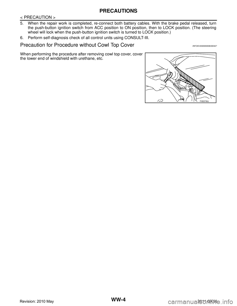
When performing the procedure after removing cowl top cover, cover
the lower end of windshield with urethane, etc.
PIIB3706J
Revision: 2010 May2011 QX56
Page 5525 of 5598
WW-6
< SYSTEM DESCRIPTION >
COMPONENT PARTS
Component Description
INFOID:0000000006300449
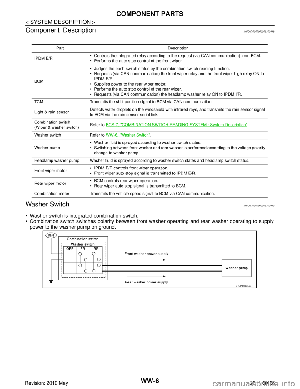
Washer SwitchINFOID:0000000006300450
Washer switch is integrated combination switch.
Combination switch switches polarity between front washer operating and rear washer operating to supply
power to the washer pump on ground.
Part Description
IPDM E/R Controls the integrated relay according to the request (via CAN communication) from BCM.
Performs the auto stop control of the front wiper.
BCM Judges the each switch status by the combination switch reading function.
Requests (via CAN communication) the front wiper relay and the front wiper high relay ON to
IPDM E/R.
Supplies power to the rear wiper motor.
Performs the auto stop control of the rear wiper.
Requests (via CAN communication) the headlamp washer relay ON to IPDM I/R.
TCM Transmits the shift position signal to BCM via CAN communication.
Light & rain sensor Detects water droplets on the windshield with infrared rays, and transmits the rain sensor signal
to BCM via the rain sensor serial link.
Combination switch
(Wiper & washer switch) Refer to
BCS-7, "
COMBINATION SWITCH READING S YSTEM : System Description".
Washer switch Refer to WW-6, "
Washer Switch".
Washer pump Washer fluid is sprayed according to washer switch states.
Switching between front washer and rear washer is performed according to the voltage polarity
change to washer pomp.
Headlamp washer pump Washer fluid is sprayed according to washer switch states and headlamp switch status.
Front wiper motor IPDM E/R controls front wiper operation.
Front wiper auto stop signal is transmitted to IPDM E/R.
Rear wiper motor BCM controls rear wiper operation.
Rear wiper auto stop signal is transmitted to BCM.
Combination meter Transmits the vehicle speed signal to BCM via CAN communication.
JPLIA0163GB
Revision: 2010 May2011 QX56
Page 5527 of 5598
WW-8
< SYSTEM DESCRIPTION >
SYSTEM
FRONT WIPER AUTO OPERATION
Rain Detection
Rain level and sensor conditions are detected by light & rain sensor.
BCM transmits the vehicle conditions (vehicle speed, front wiper condition, rain sensor sensitivity setting,
etc.) to the light & rain sensor via the rain sensor serial link.
Light & rain sensor judges a wiping speed for front wi per by rain condition and the vehicle conditions. And it
transmits the wiping speed request signal to t he BCM via the rain sensor serial link.
Auto Wiping Operation
BCM receives the wiping speed request signal from the light & rain sensor via the rain sensor serial link.
BCM controls front wiper operation according to t he wiping speed request signals. And it transmits the front
wiper request signals (LO or HI) to the IPDM E/R via CAN communication line.
Front wiper AUTO operating condition
- Ignition switch ON
- Front wiper switch AUTO
NOTE:
When the front wiper switch is turned to AUTO positi on, front wiper operates once regardless of rainy condi-
tions.
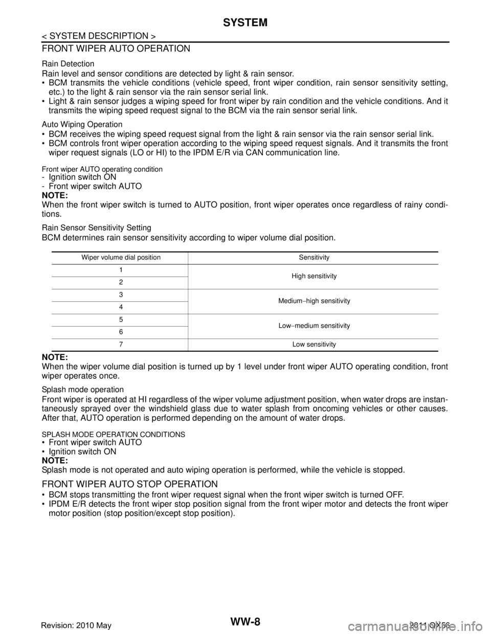
Rain Sensor Sensitivity Setting
BCM determines rain sensor sensitivity according to wiper volume dial position.
NOTE:
When the wiper volume dial position is turned up by 1 level under front wiper AUTO operating condition, front
wiper operates once.
Splash mode operation
Front wiper is operated at HI regardl ess of the wiper volume adjustment position, when water drops are instan-
taneously sprayed over the windshield glass due to wate r splash from oncoming vehicles or other causes.
After that, AUTO operation is performed depending on the amount of water drops.
SPLASH MODE OPERATION CONDITIONS Front wiper switch AUTO
Ignition switch ON
NOTE:
Splash mode is not operated and auto wiping operati on is performed, while the vehicle is stopped.
FRONT WIPER AUTO STOP OPERATION
BCM stops transmitting the front wiper request signal when the front wiper switch is turned OFF.
IPDM E/R detects the front wiper stop position signal from the front wiper motor and detects the front wiper
motor position (stop position/except stop position).
Wiper volume dial position Sensitivity
1 High sensitivity
2
3 Medium−high sensitivity
4
5 Low−medium sensitivity
6
7 Low sensitivity
Revision: 2010 May2011 QX56
Page 5537 of 5598
WW-18
< SYSTEM DESCRIPTION >
DIAGNOSIS SYSTEM (IPDM E/R)
DIAGNOSIS SYSTEM (IPDM E/R)
Diagnosis DescriptionINFOID:0000000006349814
AUTO ACTIVE TEST
Description
In auto active test, the IPDM E/R sends a drive signal to the following systems to check their operation.
Oil pressure warning lamp
Rear window defogger
Front wiper (LO, HI)
Parking lamp
License plate lamp
Tail lamp
Side marker lamp
Front fog lamp
Headlamp (LO, HI)
A/C compressor (magnet clutch)
Operation Procedure
CAUTION:
Never perform auto active test in the following conditions.
Engine is running.
CONSULT-III is connected.
1. Close the hood and lift the wiper arms from the windshield. (Prevent windshield damage due to wiper
operation)
NOTE:
When auto active test is performed with hood opened, sprinkle water on windshield beforehand.
2. Turn the ignition switch OFF.
3. Turn the ignition switch ON, and within 20 seconds, pr ess the driver door switch 10 times. Then turn the
ignition switch OFF.
CAUTION:
Close passenger door.
4. Turn the ignition switch ON within 10 seconds. Af ter that the horn sounds once and the auto active test
starts.
CAUTION:
Engine starts when igniti on switch is turned ON while brake pedal is depressed.
5. The oil pressure warning lamp starts blinking when the auto active test starts.
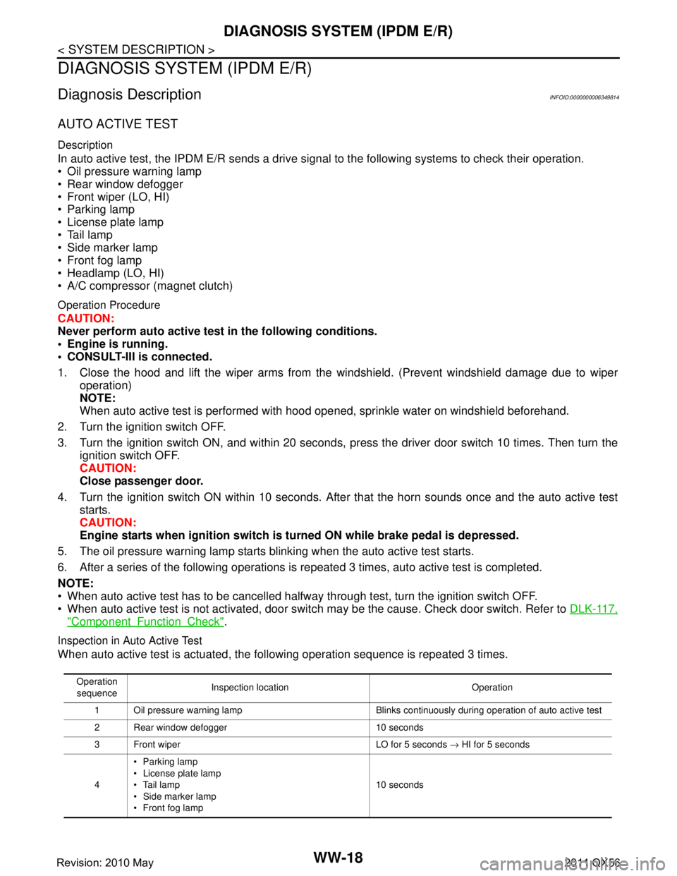
6. After a series of the following operations is repeated 3 times, auto active test is completed.
NOTE:
When auto active test has to be cancelled halfway through test, turn the ignition switch OFF.
When auto active test is not activated, door swit ch may be the cause. Check door switch. Refer to DLK-117,
"ComponentFunctionCheck".
Inspection in Auto Active Test
When auto active test is actuated, the following operation sequence is repeated 3 times.
Operation
sequence Inspection location Operation
1 Oil pressure warning lamp Blinks continuously during operation of auto active test
2 Rear window defogger 10 seconds
3 Front wiper LO for 5 seconds → HI for 5 seconds
4 Parking lamp
License plate lamp
Tail lamp
Side marker lamp
Front fog lamp 10 seconds
Revision: 2010 May2011 QX56