Page 3758 of 5598

MWI
SYSTEMMWI-15
< SYSTEM DESCRIPTION >
C
DE
F
G H
I
J
K L
M B A
O P
REFUEL CONTROL
The combination meter accelerates the fuel gauge if the all conditions listed below are met, or the ignition
switch is ON from OFF.
Ignition switch is ON position.
The vehicle is not moving.
The fuel level change by 15 (4 US gal, 3-1/4 Imp gal) or more.
ENGINE OIL PRESSURE GAUGE
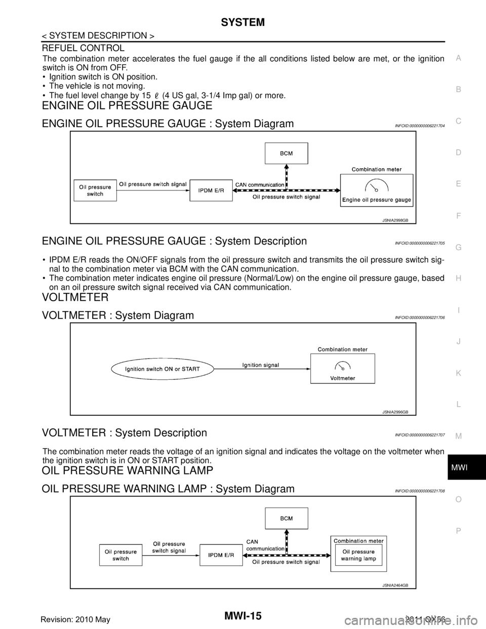
ENGINE OIL PRESSURE GAUGE : System DiagramINFOID:0000000006221704
ENGINE OIL PRESSURE GAUGE : System DescriptionINFOID:0000000006221705
IPDM E/R reads the ON/OFF signals from the oil pressure switch and transmits the oil pressure switch sig-
nal to the combination meter via BCM with the CAN communication.
The combination meter indicates engine oil pressure (Normal/Low) on the engine oil pressure gauge, based
on an oil pressure switch signal received via CAN communication.
VOLTMETER
VOLTMETER : System DiagramINFOID:0000000006221706
VOLTMETER : System DescriptionINFOID:0000000006221707
The combination meter reads the voltage of an ignition signal and indicates the voltage on the voltmeter when
the ignition switch is in ON or START position.
OIL PRESSURE WARNING LAMP
OIL PRESSURE WARNING LAMP : System DiagramINFOID:0000000006221708
JSNIA2998GB
JSNIA2996GB
JSNIA2464GB
Revision: 2010 May2011 QX56
Page 3759 of 5598

MWI-16
< SYSTEM DESCRIPTION >
SYSTEM
OIL PRESSURE WARNING LAMP : System Description
INFOID:0000000006221709
IPDM E/R reads the ON/OFF signals fr om the oil pressure switch and transmits the oil pressure switch sig-
nal to the combination meter via BCM with the CAN communication.
The combination meter turns the oil pressure warning lamp ON (at the time of a reduction in hydraulic pres-
sure)/OFF (except at the time of a reduction in hydraulic pressure) according to the oil pressure switch signal
received via CAN communication.
MASTER WARNING LAMP
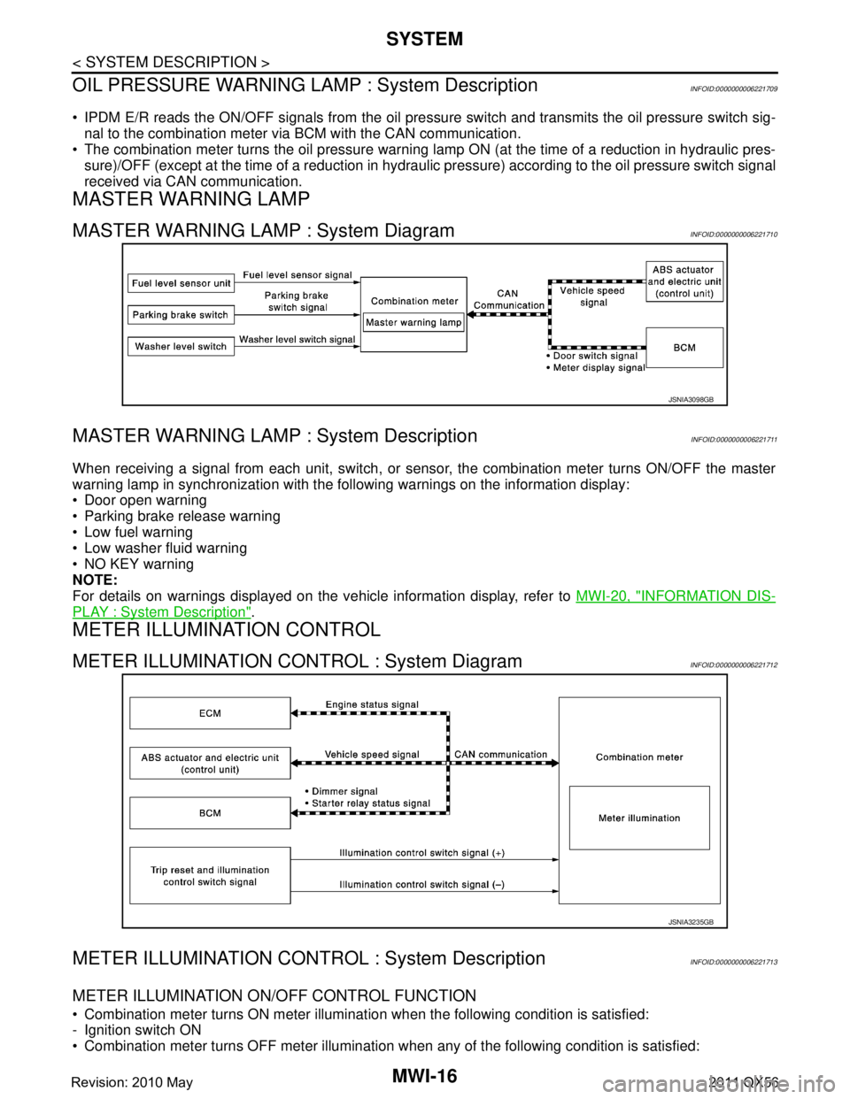
MASTER WARNING LAMP : System DiagramINFOID:0000000006221710
MASTER WARNING LAMP : System DescriptionINFOID:0000000006221711
When receiving a signal from each unit, switch, or s ensor, the combination meter turns ON/OFF the master
warning lamp in synchronization with the following warnings on the information display:
Door open warning
Parking brake release warning
Low fuel warning
Low washer fluid warning
NO KEY warning
NOTE:
For details on warnings displayed on the vehicle information display, refer to MWI-20, "
INFORMATION DIS-
PLAY : System Description".
METER ILLUMINATION CONTROL
METER ILLUMINATION CONTROL : System DiagramINFOID:0000000006221712
METER ILLUMINATION CONTRO L : System DescriptionINFOID:0000000006221713
METER ILLUMINATION ON/OFF CONTROL FUNCTION
Combination meter turns ON meter illumination when the following condition is satisfied:
- Ignition switch ON
Combination meter turns OFF meter illumination when any of the following condition is satisfied:
JSNIA3098GB
JSNIA3235GB
Revision: 2010 May2011 QX56
Page 3760 of 5598

MWI
SYSTEMMWI-17
< SYSTEM DESCRIPTION >
C
DE
F
G H
I
J
K L
M B A
O P
- During a crank with vehicle speed less than 1 km/h (0.6 MPH)
- Ignition switch OFF or ACC
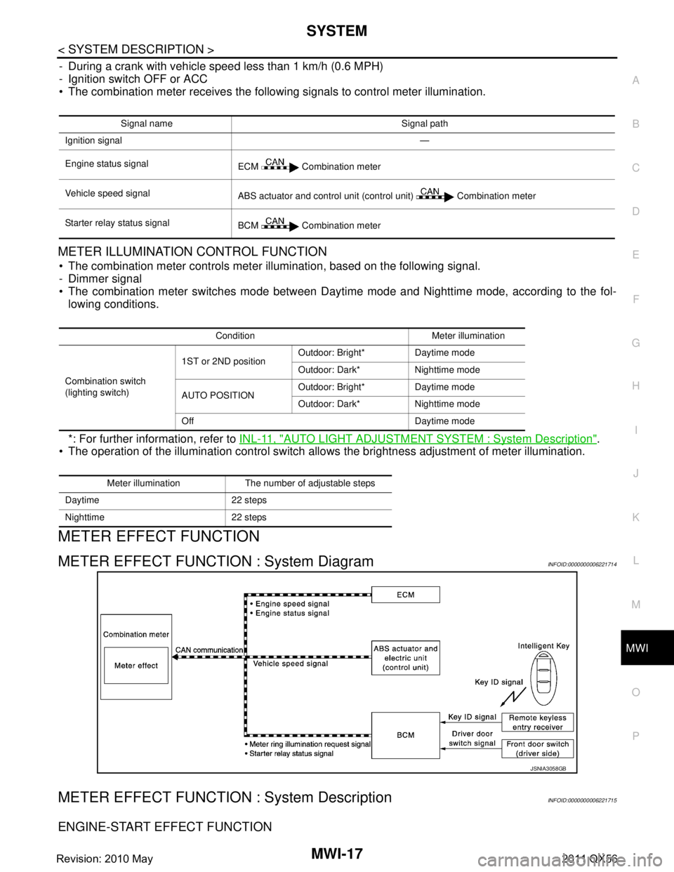
The combination meter receives the following signals to control meter illumination.
METER ILLUMINATION CONTROL FUNCTION
The combination meter controls meter illumination, based on the following signal.
- Dimmer signal
The combination meter switches mode between Daytim e mode and Nighttime mode, according to the fol-
lowing conditions.
*: For further information, refer to INL-11, "
AUTO LIGHT ADJUSTMENT SYSTEM : System Description".
The operation of the illumination control switch allo ws the brightness adjustment of meter illumination.
METER EFFECT FUNCTION
METER EFFECT FUNCTION : System DiagramINFOID:0000000006221714
METER EFFECT FUNCTION : System DescriptionINFOID:0000000006221715
ENGINE-START EFFECT FUNCTION
Signal name Signal path
Ignition signal —
Engine status signal ECM Combination meter
Vehicle speed signal ABS actuator and control unit (control unit) Combination meter
Starter relay status signal BCM Combination meter
Condition Meter illumination
Combination switch
(lighting switch) 1ST or 2ND position
Outdoor: Bright* Daytime mode
Outdoor: Dark* Nighttime mode
AUTO POSITION Outdoor: Bright* Daytime mode
Outdoor: Dark* Nighttime mode
Off Daytime mode
Meter illumination The number of adjustable steps
Daytime 22 steps
Nighttime 22 steps
JSNIA3058GB
Revision: 2010 May2011 QX56
Page 3762 of 5598
MWI
SYSTEMMWI-19
< SYSTEM DESCRIPTION >
C
DE
F
G H
I
J
K L
M B A
O P
BCM transmits a meter ring illumination request signal to the illumination meter when all the following opera-
tional conditions are satisfied. When receiving the meter ring illumination request signal from BCM via CAM
communication, the combination meter increases illuminat ion brightness of the combination meter to the set
brightness level in stages. After a certain period of time, the meter illumination gradually dims to be turned
OFF.
*: Close the driver side door with the intelligent key left inside the vehicle.
Timing Chart
INFORMATION DISPLAY
INFORMATION DISPLAY : System DiagramINFOID:0000000006221716
Operational condition
Ignition switch LOCK position
Driver door Open→Close
*
JSNIA3099GB
JSNIA2997GB
Revision: 2010 May2011 QX56
Page 3788 of 5598
MWI
METER SYSTEMMWI-45
< WIRING DIAGRAM >
C
DE
F
G H
I
J
K L
M B A
O P
WIRING DIAGRAM
METER SYSTEM
Wiring DiagramINFOID:0000000006221725
JCNWM4795GB
Revision: 2010 May2011 QX56
Page 3789 of 5598
MWI-46
< WIRING DIAGRAM >
METER SYSTEM
JCNWM4796GB
Revision: 2010 May2011 QX56
Page 3790 of 5598
MWI
METER SYSTEMMWI-47
< WIRING DIAGRAM >
C
DE
F
G H
I
J
K L
M B A
O P
JCNWM4797GB
Revision: 2010 May2011 QX56
Page 3791 of 5598
MWI-48
< WIRING DIAGRAM >
METER SYSTEM
JCNWM4798GB
Revision: 2010 May2011 QX56