2011 INFINITI QX56 diagram
[x] Cancel search: diagramPage 3723 of 5598
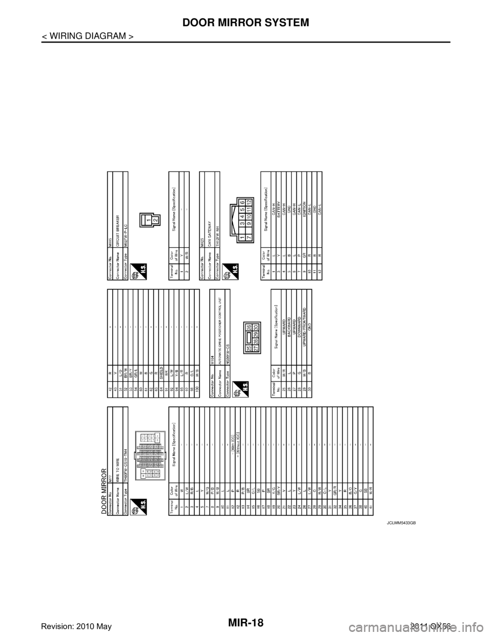
MIR-18
< WIRING DIAGRAM >
DOOR MIRROR SYSTEM
JCLWM5433GB
Revision: 2010 May2011 QX56
Page 3724 of 5598
AUTO ANTI-DAZZLING INSIDE MIRROR SYSTEMMIR-19
< WIRING DIAGRAM >
C
DE
F
G H
I
J
K
M A
B
MIR
N
O P
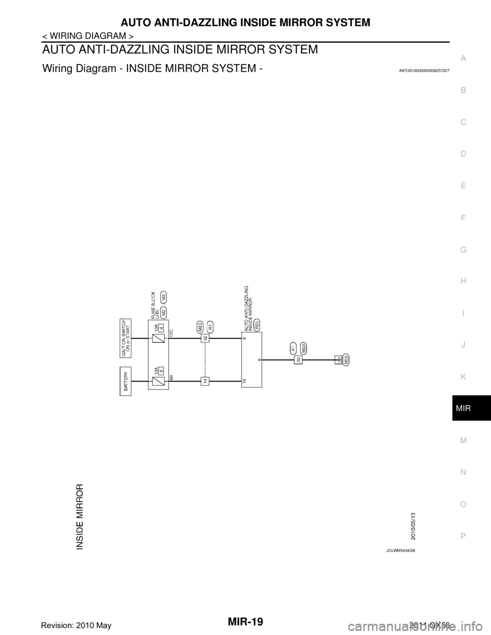
AUTO ANTI-DAZZLING INSIDE MIRROR SYSTEM
Wiring Diagram - INSIDE MIRROR SYSTEM -INFOID:0000000006257227
JCLWM5434GB
Revision: 2010 May2011 QX56
Page 3725 of 5598
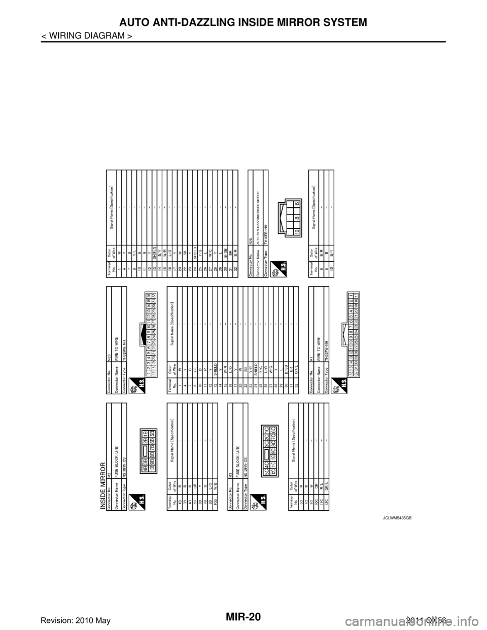
MIR-20
< WIRING DIAGRAM >
AUTO ANTI-DAZZLING INSIDE MIRROR SYSTEM
JCLWM5435GB
Revision: 2010 May2011 QX56
Page 3744 of 5598
MWI
MWI-1
DRIVER INFORMATION & MULTIMEDIA
C
DE
F
G H
I
J
K L
M B
SECTION MWI
A
O P
CONTENTS
METER, WARNING LAMP & INDICATOR
PRECAUTION ................ ...............................4
PRECAUTIONS .............................................. .....4
Precaution for Supplemental Restraint System
(SRS) "AIR BAG" and "SEAT BELT PRE-TEN-
SIONER" ............................................................. ......
4
PREPARATION ............................................5
PREPARATION .............................................. .....5
Commercial Service Tools .................................. ......5
SYSTEM DESCRIPTION ..............................6
COMPONENT PARTS ................................... .....6
METER SYSTEM .........................................................6
METER SYSTEM : Component Parts Location .. ......6
METER SYSTEM : Component Description .............7
CLOCK .................................................................. ......7
CLOCK : Component Parts Location ........................8
SYSTEM ..............................................................9
METER SYSTEM .........................................................9
METER SYSTEM : System Diagram ........................9
METER SYSTEM : System Description ....................9
METER SYSTEM : Fail-Safe ..................................12
SPEEDOMETER ................ ........................................13
SPEEDOMETER : System Diagram ................... ....13
SPEEDOMETER : System Description ...................13
TACHOMETER ...................................................... ....13
TACHOMETER : System Diagram .........................14
TACHOMETER : System Description .....................14
ENGINE COOLANT TEMPERATURE GAUGE .... ....14
ENGINE COOLANT TEMPERATURE GAUGE :
System Diagram ......................................................
14
ENGINE COOLANT TEMPERATURE GAUGE :
System Description .................................................
14
FUEL GAUGE ........................................................ ....14
FUEL GAUGE : System Diagram ............................14
FUEL GAUGE : System Description .......................14
ENGINE OIL PRESSURE GAUGE ............................15
ENGINE OIL PRESSURE GAUGE : System Dia-
gram .................................................................... ....
15
ENGINE OIL PRESSURE GAUGE : System De-
scription ...................................................................
15
VOLTMETER ......................................................... ....15
VOLTMETER : System Diagram .............................15
VOLTMETER : System Description .........................15
OIL PRESSURE WARNING LAMP ...........................15
OIL PRESSURE WARNING LAMP : System Dia-
gram .................................................................... ....
15
OIL PRESSURE WARNING LAMP : System De-
scription ...................................................................
16
MASTER WARNING LAMP ................................... ....16
MASTER WARNING LAMP : System Diagram .......16
MASTER WARNING LAMP : System Description ....16
METER ILLUMINATION CONTROL ..................... ....16
METER ILLUMINATION CONTROL : System Di-
agram ......................................................................
16
METER ILLUMINATION CONTROL : System De-
scription ...................................................................
16
METER EFFECT FUNCTION ................................ ....17
METER EFFECT FUNCTION : System Diagram ....17
METER EFFECT FUNCTION : System Descrip-
tion ...........................................................................
17
INFORMATION DISPLAY ...................................... ....19
INFORMATION DISPLAY : System Diagram ..........19
INFORMATION DISPLAY : System Description .....20
OPERATION .....................................................28
Switch Name and Function ......................................28
Revision: 2010 May2011 QX56
Page 3745 of 5598

MWI-2
DIAGNOSIS SYSTEM (COMBINATION
METER) ..............................................................
29
On Board Diagnosis Function .............................. ...29
CONSULT-III Function ...........................................30
ECU DIAGNOSIS INFORMATION ..............35
COMBINATION METER ................................. ...35
Reference Value .................................................. ...35
Fail-Safe .................................................................42
DTC Index ..............................................................43
IPDM E/R ...........................................................44
List of ECU Reference ......................................... ...44
WIRING DIAGRAM .....................................45
METER SYSTEM ............................................ ...45
Wiring Diagram .................................................... ...45
CLOCK ...............................................................55
Wiring Diagram .................................................... ...55
BASIC INSPECTION ...................................57
DIAGNOSIS AND REPAIR WORKFLOW
(METER SYSTEM ) .......................................... ...
57
Work flow ............................................................. ...57
DTC/CIRCUIT DIAGNOSIS ...................... ...59
U1000 CAN COMM CIRCUIT ......................... ...59
Description ........................................................... ...59
DTC Logic ...............................................................59
Diagnosis Procedure .............................................59
U1010 CONTROL UNIT (CAN) .........................60
Description ........................................................... ...60
DTC Logic ...............................................................60
Diagnosis Procedure ..............................................60
B2205 VEHICLE SPEED ...................................61
Description ........................................................... ...61
DTC Logic ...............................................................61
Diagnosis Procedure .............................................61
B2267 ENGINE SPEED .....................................62
Description ........................................................... ...62
DTC Logic ...............................................................62
Diagnosis Procedure ..............................................62
B2268 WATER TEMP ........................................63
Description ........................................................... ...63
DTC Logic ...............................................................63
Diagnosis Procedure ..............................................63
POWER SUPPLY AND GROUND CIRCUIT .....64
COMBINATION METER ........................................ ...64
COMBINATION METER : Diagnosis Procedure ....64
TRIP RESET AND ILLUMINATION CON-
TROL SWITCH SIGNAL CIRCUIT ....................
65
Diagnosis Procedure ............................................ ...65
Component Inspection ............................................66
TRIP COMPUTER SWITCH SIGNAL CIRCUIT
...
67
Diagnosis Procedure ............................................ ...67
Component Inspection ............................................68
FUEL LEVEL SENSOR SIGNAL CIRCUIT .......69
Component Function Check ................................ ...69
Diagnosis Procedure ..............................................69
Component Inspection ............................................70
OIL PRESSURE SWITCH SIGNAL CIRCUIT ...71
Component Function Check ...................................71
Diagnosis Procedure ...............................................71
Component Inspection ............................................71
WASHER LEVEL SWITCH SIGNAL CIRCUIT ...73
Diagnosis Procedure ............................................ ...73
Component Inspection ............................................73
A/C AUTO AMP. CONNECTION RECOGNI-
TION SIGNAL CIRCUIT ....................................
74
Diagnosis Procedure ........................................... ...74
SYMPTOM DIAGNOSIS ............................75
THE FUEL GAUGE INDICATOR DOES NOT
OPERATE ....................................................... ...
75
Description ........................................................... ...75
Diagnosis Procedure ...............................................75
THE TRIP RESET AND ILLUMINATION CON-
TROL SWITCH IS INOPERATIVE ....................
76
Description ........................................................... ...76
Diagnosis Procedure ...............................................76
THE TRIP COMPUTER SWITCH IS INOPER-
ATIVE .................................................................
77
Description ........................................................... ...77
Diagnosis Procedure ...............................................77
THE OIL PRESSURE WARNING LAMP
DOES NOT TURN ON .................................... ...
78
Description ........................................................... ...78
Diagnosis Procedure ...............................................78
THE OIL PRESSURE WARNING LAMP
DOES NOT TURN OFF .................................. ...
79
Description ........................................................... ...79
Diagnosis Procedure ...............................................79
THE PARKING BRAKE RELEASE WARNING
CONTINUES DISPLAYING, OR DOES NOT
DISPLAY ............................................................
80
Description ........................................................... ...80
Diagnosis Procedure ...............................................80
Revision: 2010 May2011 QX56
Page 3752 of 5598

MWI
SYSTEMMWI-9
< SYSTEM DESCRIPTION >
C
DE
F
G H
I
J
K L
M B A
O P
SYSTEM
METER SYSTEM
METER SYSTEM : System DiagramINFOID:0000000006221693
METER SYSTEM : System DescriptionINFOID:0000000006221694
COMBINATION METER
The combination meter receives necessary signals from each unit, switch, and sensor to control the follow-
ing functions.
- Measuring instruments
- Warning lamps
- Indicator lamps
- Meter illumination control
- Meter effect function
- Information display
The combination meter incorporates a buzzer func tion that sounds an audible alarm with the integrated
buzzer device. Refer to WCS-5, "
Combination Meter" for further details.
The combination meter includes an on board diagnosis function.
The combination meter can be diagnosed with CONSULT-III.
METER CONTROL FUNCTION LIST
JSNIA2995GB
Revision: 2010 May2011 QX56
Page 3756 of 5598
MWI
SYSTEMMWI-13
< SYSTEM DESCRIPTION >
C
DE
F
G H
I
J
K L
M B A
O P
SPEEDOMETER
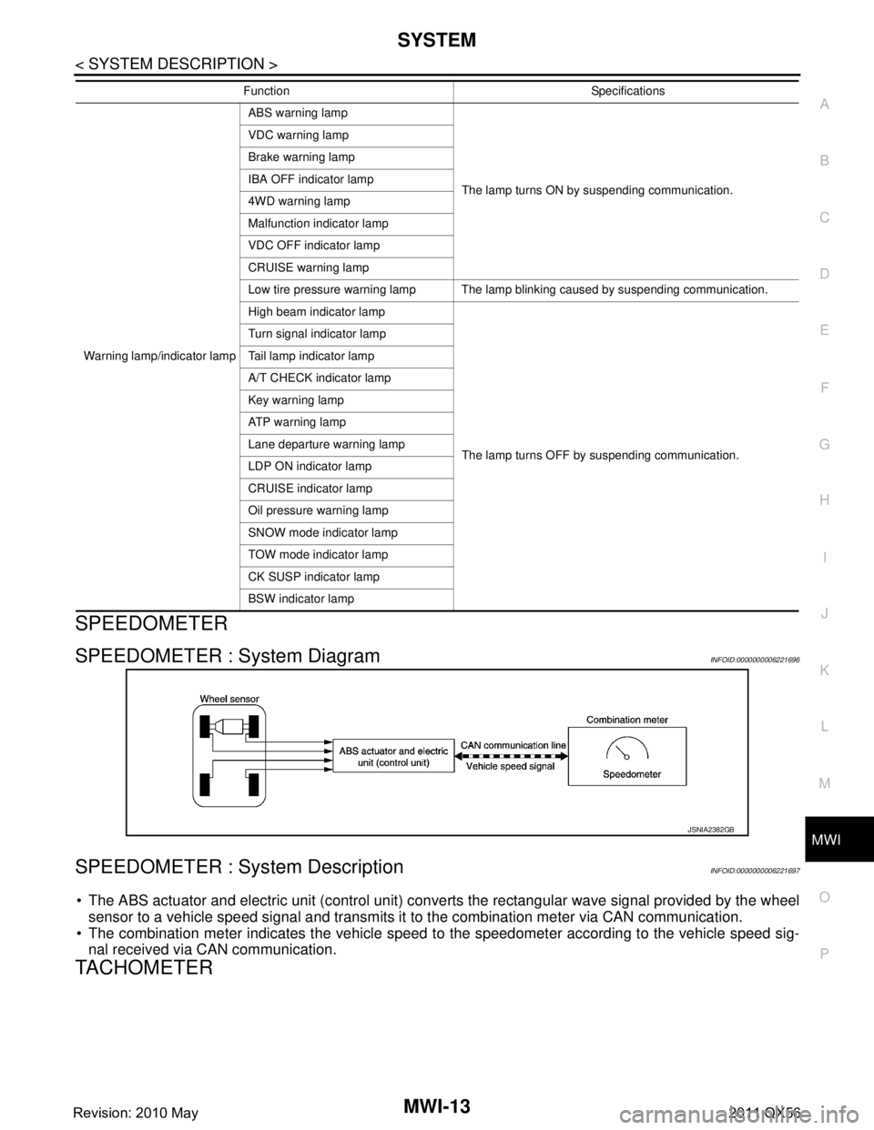
SPEEDOMETER : System DiagramINFOID:0000000006221696
SPEEDOMETER : System DescriptionINFOID:0000000006221697
The ABS actuator and electric unit (control unit) conv erts the rectangular wave signal provided by the wheel
sensor to a vehicle speed signal and transmits it to the combination meter via CAN communication.
The combination meter indicates the vehicle speed to the speedometer according to the vehicle speed sig-
nal received via CAN communication.
TACHOMETER
Warning lamp/indicator lamp ABS warning lamp
The lamp turns ON by suspending communication.
VDC warning lamp
Brake warning lamp
IBA OFF indicator lamp
4WD warning lamp
Malfunction indicator lamp
VDC OFF indicator lamp
CRUISE warning lamp
Low tire pressure warning lamp The lamp blinking caused by suspending communication.
High beam indicator lamp
The lamp turns OFF by suspending communication.
Turn signal indicator lamp
Tail lamp indicator lamp
A/T CHECK indicator lamp
Key warning lamp
AT P w a r n i n g l a m p
Lane departure warning lamp
LDP ON indicator lamp
CRUISE indicator lamp
Oil pressure warning lamp
SNOW mode indicator lamp
TOW mode indicator lamp
CK SUSP indicator lamp
BSW indicator lamp
Function Specifications
JSNIA2382GB
Revision: 2010 May2011 QX56
Page 3757 of 5598
MWI-14
< SYSTEM DESCRIPTION >
SYSTEM
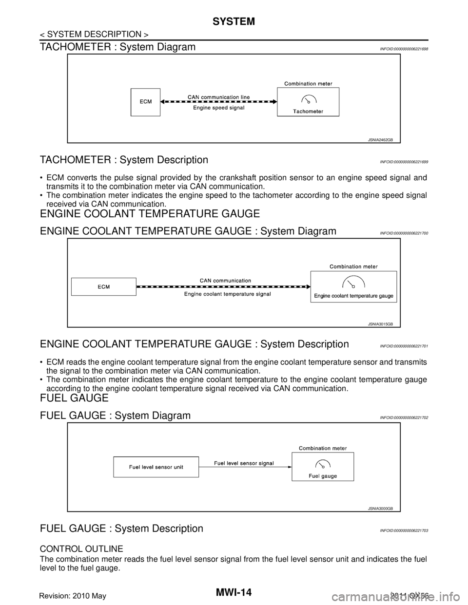
TACHOMETER : System Diagram
INFOID:0000000006221698
TACHOMETER : System DescriptionINFOID:0000000006221699
ECM converts the pulse signal provided by the crankshaft position sensor to an engine speed signal and
transmits it to the combination meter via CAN communication.
The combination meter indicates the engine speed to the tachometer according to the engine speed signal
received via CAN communication.
ENGINE COOLANT TEMPERATURE GAUGE
ENGINE COOLANT TEMPERATURE GAUGE : System DiagramINFOID:0000000006221700
ENGINE COOLANT TEMPERATURE GAUGE : System DescriptionINFOID:0000000006221701
ECM reads the engine coolant temperature signal from the engine coolant temperature sensor and transmits
the signal to the combination meter via CAN communication.
The combination meter indicates the engine coolant temperature to the engine coolant temperature gauge
according to the engine coolant temperature signal received via CAN communication.
FUEL GAUGE
FUEL GAUGE : System DiagramINFOID:0000000006221702
FUEL GAUGE : System DescriptionINFOID:0000000006221703
CONTROL OUTLINE
The combination meter reads the fuel level sensor signal from the fuel level sensor unit and indicates the fuel
level to the fuel gauge.
JSNIA2462GB
JSNIA3015GB
JSNIA3000GB
Revision: 2010 May2011 QX56