2011 INFINITI QX56 charging
[x] Cancel search: chargingPage 3100 of 5598

HA-44
< REMOVAL AND INSTALLATION >
A/C UNIT ASSEMBLY
INSTALLATION
Note the following items, and install in the reverse order of removal.
CAUTION:
Replace O-rings with new ones. Then apply compressor oil to them when installing.
When install the intake sensor, set the same position before replacement.
Never rotate the bracket insertion part when removing and installing the intake sensor.
Perform lubricant adjusting procedure af ter installing new evaporator. Refer to HA-22, "
Lubricant
Adjusting Procedure for Components Replacement Except Compressor".
HEATER CORE
HEATER CORE : Removal and InstallationINFOID:0000000006276185
REMOVAL
1. Remove heater & cooling unit assembly. Refer to HA-42, "HEATER & COOLING UNIT ASSEMBLY :
Removal and Installation".
2. Remove mounting screws, and then remove heater core pipe cover.
3. Remove mode door motor. Refer to HAC-153, "
MODE DOOR MOTOR : Removal and Installation".
4. Remove main link, foot door link and foot door lever. Refer to HAC-152, "
Exploded View".
5. Remove mounting screws, and then remove foot duct (assist side). Refer to VTL-11, "
FLOOR DUCT 1 :
Removal and Installation".
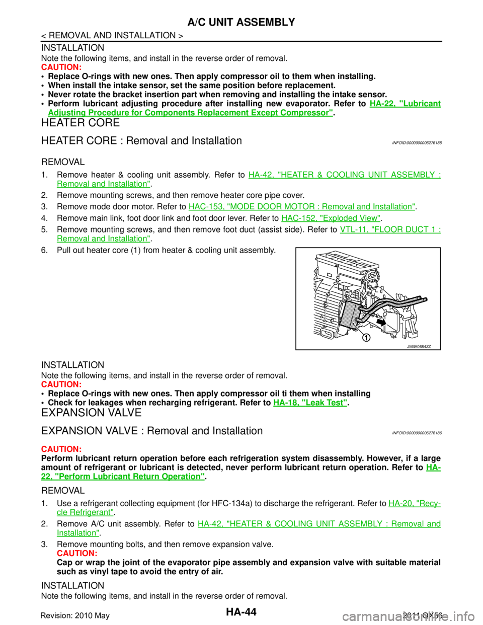
6. Pull out heater core (1) from heater & cooling unit assembly.
INSTALLATION
Note the following items, and install in the reverse order of removal.
CAUTION:
Replace O-rings with new ones. Then apply compressor oil ti them when installing
Check for leakages when recharging refrigerant. Refer to HA-18, "
Leak Test".
EXPANSION VALVE
EXPANSION VALVE : Removal and InstallationINFOID:0000000006276186
CAUTION:
Perform lubricant return operation before each refrigeration system disassembly. However, if a large
amount of refrigerant or lubrican t is detected, never perform lubricant return operation. Refer to HA-
22, "Perform Lubricant Return Operation".
REMOVAL
1. Use a refrigerant collecting equipment (for HF C-134a) to discharge the refrigerant. Refer to HA-20, "Recy-
cle Refrigerant".
2. Remove A/C unit assembly. Refer to HA-42, "
HEATER & COOLING UNIT ASSEMBLY : Removal and
Installation".
3. Remove mounting bolts, and then remove expansion valve. CAUTION:
Cap or wrap the joint of the evaporator pipe assembly and expansion valve with suitable material
such as vinyl tape to avoid the entry of air.
INSTALLATION
Note the following items, and install in the reverse order of removal.
JMIIA0684ZZ
Revision: 2010 May2011 QX56
Page 3101 of 5598

A/C UNIT ASSEMBLYHA-45
< REMOVAL AND INSTALLATION >
C
DE
F
G H
J
K L
M A
B
HA
N
O P
CAUTION:
Replace O-rings with new ones. Then apply compressor oil to them when installing.
Check for leakages when recharging refrigerant. Refer to HA-18, "
Leak Test".
Revision: 2010 May2011 QX56
Page 3104 of 5598

HA-48
< REMOVAL AND INSTALLATION >
REAR A/C UNIT
CAUTION:
Cap or wrap the joint of the A/C piping with suitable material such as vinyl tape to avoid the entry
of air.
6. Remove clamps, and then disconnect rear heater pipe from rear cooler pipe assembly.
7. Remove jack from the vehicle.
8. Remove mounting bolts and nuts, and then remove rear A/C unit assembly.
INSTALLATION
Note the following items, and install in the reverse order of removal.
CAUTION:
Replace O-rings with new ones. Then apply compressor oil to them when installing.
Check for leakages when recharging refrigerant. Refer to HA-18, "
Leak Test".
EVAPORATOR
EVAPORATOR : Removal and InstallationINFOID:0000000006276189
REMOVAL
1. Remove rear A/C unit assembly. Refer to HA-47, "REAR A/C UNIT ASSEMBLY : Removal and Installa-
tion".
2. Disassemble rear A/C unit, and then remove rear evaporator assembly.
3. Remove mounting bolt, and then remove rear evaporator from rear evaporator assembly.
INSTALLATION
Note the following items, and install in the reverse order of removal.
CAUTION:
Replace O-rings with new ones. Then apply compressor oil to them when installing.
Check for leakages when recharging refrigerant. Refer to HA-18, "
Leak Test".
EVAPORATOR PIPE ASSEMBLY
EVAPORATOR PIPE ASSEMBLY : Removal and InstallationINFOID:0000000006276190
REMOVAL
1. Remove rear evaporator assembly. Refer to HA-48, "EVAPORATOR : Removal and Installation".
2. Remove mounting bolts, and then rear expansion valve from rear evaporator assembly. CAUTION:
Cap or wrap the joint of the A/C piping and rear expansion valve with suitable material such as
vinyl tape to avoid the entry of air.
3. Remove mounting bolts, and then remove evaporat or pipe assembly from evaporator assembly.
INSTALLATION
Note the following items, and install in the reverse order of removal.
CAUTION:
Replace O-rings with new ones. Then apply compressor oil to them when installing.
Check for leakages when recharging refrigerant. Refer to HA-18, "
Leak Test".
HEATER CORE
HEATER CORE : Removal and InstallationINFOID:0000000006276191
REMOVAL
1. Remove rear A/C unit assembly. Refer to HA-47, "REAR A/C UNIT ASSEMBLY : Removal and Installa-
tion"
2. Remove grommet from pipe bracket.
3. Remove mounting screws and then remove pipe bracket.
4. Remove mounting screw, and then heater pipe clamp.
Revision: 2010 May2011 QX56
Page 3105 of 5598

REAR A/C UNITHA-49
< REMOVAL AND INSTALLATION >
C
DE
F
G H
J
K L
M A
B
HA
N
O P
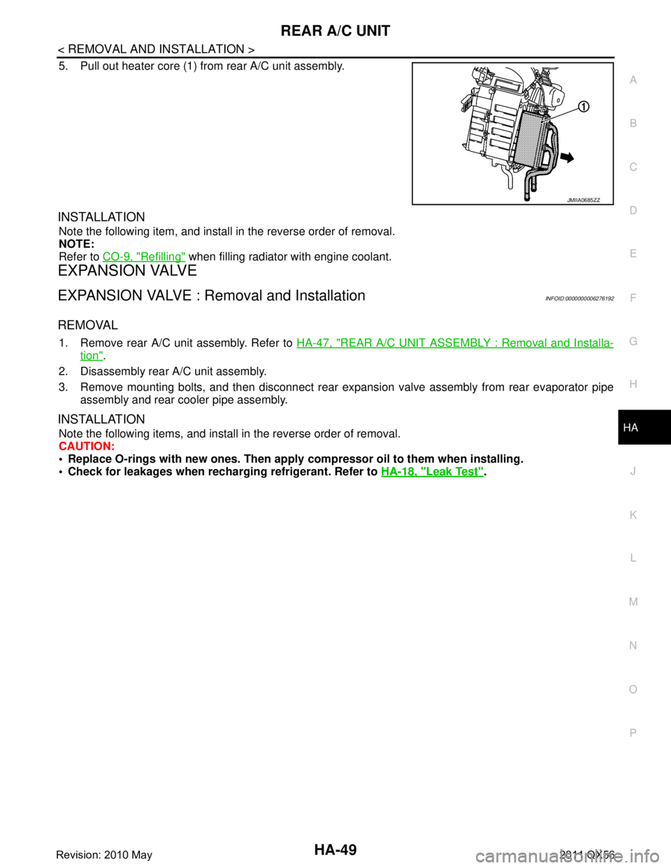
5. Pull out heater core (1) from rear A/C unit assembly.
INSTALLATION
Note the following item, and install in the reverse order of removal.
NOTE:
Refer to CO-9, "
Refilling" when filling radiator with engine coolant.
EXPANSION VALVE
EXPANSION VALVE : Removal and InstallationINFOID:0000000006276192
REMOVAL
1. Remove rear A/C unit assembly. Refer to HA-47, "REAR A/C UNIT ASSEMBLY : Removal and Installa-
tion".
2. Disassembly rear A/C unit assembly.
3. Remove mounting bolts, and then disconnect rear exp ansion valve assembly from rear evaporator pipe
assembly and rear cooler pipe assembly.
INSTALLATION
Note the following items, and install in the reverse order of removal.
CAUTION:
Replace O-rings with new ones. Then apply compressor oil to them when installing.
Check for leakages when recharging refrigerant. Refer to HA-18, "
Leak Test".
JMIIA0685ZZ
Revision: 2010 May2011 QX56
Page 3106 of 5598

HA-50
< SERVICE DATA AND SPECIFICATIONS (SDS)
SERVICE DATA AND SPECIFICATIONS (SDS)
SERVICE DATA AND SPECIFICATIONS (SDS)
SERVICE DATA AND SPECIFICATIONS (SDS)
CompressorINFOID:0000000006276197
LubricantINFOID:0000000006276198
RefrigerantINFOID:0000000006276199
Engine Idling SpeedINFOID:0000000006276200
Refer to EC-538, "Idle Speed".
Belt TensionINFOID:0000000006276201
Refer to EM-20, "TensionAdjustment".
Model VALEO THERMAL SYSTEMS JAPAN make
DSK-17D
Ty p e Fixation displacement swash plate
Displacement
cm
3 (cu in)/rev Maximum 175 (10.7)
Direction of rotation Clockwise (viewed from clutch)
Drive belt Poly V
Disc to pulley clearance
mm (in) Standard 0.3 – 0.6 (0.012 – 0.024)
Name
UV Luminaus Oil Type S (DH-PS)
Capacity
m (Imp fl oz) Total in system 210 (7.1)
Compressor (service part) charging
amount
210 (7.1)
Ty p e
HFC-134a (R-134a)
Capacity
kg (lb) 1.05 (2.32)
Revision: 2010 May2011 QX56
Page 3244 of 5598
![INFINITI QX56 2011 Factory Service Manual
HAC-138
< SYMPTOM DIAGNOSIS >[AUTOMATIC AIR CONDITIONING]
INSUFFICIENT COOLING
INSUFFICIENT COOLING
FRONT AIR CONDITIONER
FRONT AIR CONDITIONER : DescriptionINFOID:0000000006275984
Symptom Insuffici INFINITI QX56 2011 Factory Service Manual
HAC-138
< SYMPTOM DIAGNOSIS >[AUTOMATIC AIR CONDITIONING]
INSUFFICIENT COOLING
INSUFFICIENT COOLING
FRONT AIR CONDITIONER
FRONT AIR CONDITIONER : DescriptionINFOID:0000000006275984
Symptom Insuffici](/manual-img/42/57033/w960_57033-3243.png)
HAC-138
< SYMPTOM DIAGNOSIS >[AUTOMATIC AIR CONDITIONING]
INSUFFICIENT COOLING
INSUFFICIENT COOLING
FRONT AIR CONDITIONER
FRONT AIR CONDITIONER : DescriptionINFOID:0000000006275984
Symptom Insufficient cooling
No cool air comes out. (Air flow volume is normal.)
FRONT AIR CONDITIONER
: Diagnosis ProcedureINFOID:0000000006275985
NOTE:
Perform self-diagnoses with CONSULT-III before perform ing symptom diagnosis. If any DTC is detected, per-
form the corresponding diagnosis.
1.CHECK MAGNET CLUTCH OPERATION
1. Turn ignition switch ON.
2. Operate fan switch.
3. Press A/C switch.
4. Check that A/C indicator turns ON. Check visually and by sound that compressor operates.
5. Press A/C switch again.
6. Check that A/C indicator turns OFF. Check that compressor stops.
Is the inspection result normal?
YES >> GO TO 2.
NO >> Perform diagnosis of “COMPRESSOR DOSE NOT OPERATE” in “SYMPTOM DIAGNOSIS”.
Refer to HAC-142, "
Diagnosis Procedure".
2.CHECK DRIVE BELT
Check tension of drive belt. Refer to EM-20, "
Checking".
Is the inspection result normal?
YES >> GO TO 3.
NO >> Adjust or replace drive belt depending on the inspection results.
3.CHECK REFRIGERANT CYCLE
Connect recovery/recycling recharging equipment to the vehicle and perform pressure inspection with gauge.
Refer to HA-27, "
Symptom Table".
Is the inspection result normal?
YES >> GO TO 4.
NO >> Repair or replace parts depending on the inspection results.
4.CHECK AIR LEAKAGE FROM EACH DUCT
Check duct and nozzle, etc. of the fr ont air conditioning system for leakage.
Is the inspection result normal?
YES >> GO TO 5.
NO >> Repair or replace parts depending on the inspection results.
5.CHECK AMBIENT TEMPERATURE DISPLAY
Check that there is not much diference between act ual ambient temperature and indicated temperature on
information display in combination meter.
Is the inspection result normal?
YES >> GO TO 6.
NO >> Perform diagnosis for the A/C auto amp. connection recognition signal circuit. Refer to MWI-74,
"DiagnosisProcedure".
6.CHECK SETTING OF TEMPERATURE SETTING TRIMMER (FRONT)
1. Check setting value of temperature setting trimmer (front). Refer to HAC-68, "
FRONT AUTOMATIC AIR
CONDITIONING SYSTEM : Temperature Setting Trimmer (Front)".
2. Check that temperature setting trimme r (front) is set to “+ direction”.
Revision: 2010 May2011 QX56
Page 3245 of 5598
![INFINITI QX56 2011 Factory Service Manual
INSUFFICIENT COOLINGHAC-139
< SYMPTOM DIAGNOSIS > [AUTOMATIC AIR CONDITIONING]
C
D
E
F
G H
J
K L
M A
B
HAC
N
O P
NOTE:
The control temperature can be set with the setti ng of the temperature setting INFINITI QX56 2011 Factory Service Manual
INSUFFICIENT COOLINGHAC-139
< SYMPTOM DIAGNOSIS > [AUTOMATIC AIR CONDITIONING]
C
D
E
F
G H
J
K L
M A
B
HAC
N
O P
NOTE:
The control temperature can be set with the setti ng of the temperature setting](/manual-img/42/57033/w960_57033-3244.png)
INSUFFICIENT COOLINGHAC-139
< SYMPTOM DIAGNOSIS > [AUTOMATIC AIR CONDITIONING]
C
D
E
F
G H
J
K L
M A
B
HAC
N
O P
NOTE:
The control temperature can be set with the setti ng of the temperature setting trimmer (front).
3. Set difference between set temperature and control temperature to “0”.
Is inspection result normal?
YES >> INSPECTION END
NO >> Replace A/C auto amp.. Refer to HAC-146, "
Removal and Installation".
REAR AIR CONDITIONER
REAR AIR CONDITIONER : DescriptionINFOID:0000000006275986
Symptom Insufficient cooling
No cool air comes out. (Air flow volume is normal.)
REAR AIR CONDITIONER : Diagnosis ProcedureINFOID:0000000006275987
NOTE:
Perform self-diagnoses with CONSULT-III before performi ng symptom diagnosis. If any DTC is detected, per-
form the corresponding diagnosis.
1.CHECK REAR A/C SOLENOID VALVE
Check rear A/C solenoid valve. Refer to HAC-128, "
Diagnosis Procedure".
Is the inspection result normal?
YES >> GO TO 2.
NO >> Repair or replace malfunctioning parts.
2.CHECK REFRIGERANT CYCLE
Connect recovery/recycling recharging equipment to t he vehicle and perform pressure inspection with gauge.
Refer to HA-27, "
Symptom Table".
Is the inspection result normal?
YES >> GO TO 3.
NO >> Repair or replace parts depending on the inspection results.
3.CHECK AIR LEAKAGE FROM EACH DUCT
Check duct and nozzle, etc. of the rear air conditioning system for leakage.
Is the inspection result normal?
YES >> GO TO 4.
NO >> Repair or replace parts depending on the inspection results.
4.CHECK SETTING OF TEMPERATURE SETTING TRIMMER (REAR)
1. Check setting value of temperature setting trimmer (rear). Refer to HAC-69, "
REAR AUTOMATIC AIR
CONDITIONING SYSTEM : Temperature Setting Trimmer (Rear)".
2. Check that temperature setting trimmer (rear) is set to “+ direction”. NOTE:
The control temperature can be set with the sett ing of the temperature setting trimmer (rear).
3. Set difference between set temperature and control temperature to “0”.
Is inspection result normal?
YES >> INSPECTION END
NO >> Replace A/C auto amp.. Refer to HAC-146, "
Removal and Installation".
Revision: 2010 May2011 QX56
Page 3254 of 5598
![INFINITI QX56 2011 Factory Service Manual
HAC-148
< REMOVAL AND INSTALLATION >[AUTOMATIC AIR CONDITIONING]
IN-VEHICLE SENSOR
IN-VEHICLE SENSOR
FRONT A/C UNIT ASSEMBLY
FRONT A/C UNIT ASSEMBLY :
Removal and InstallationINFOID:0000000006276001 INFINITI QX56 2011 Factory Service Manual
HAC-148
< REMOVAL AND INSTALLATION >[AUTOMATIC AIR CONDITIONING]
IN-VEHICLE SENSOR
IN-VEHICLE SENSOR
FRONT A/C UNIT ASSEMBLY
FRONT A/C UNIT ASSEMBLY :
Removal and InstallationINFOID:0000000006276001](/manual-img/42/57033/w960_57033-3253.png)
HAC-148
< REMOVAL AND INSTALLATION >[AUTOMATIC AIR CONDITIONING]
IN-VEHICLE SENSOR
IN-VEHICLE SENSOR
FRONT A/C UNIT ASSEMBLY
FRONT A/C UNIT ASSEMBLY :
Removal and InstallationINFOID:0000000006276001
REMOVAL
1. Remove instrument lower panel LH. Refer to IP-14, "Removal and Installation".
2. Remove fixing screw, and then remove in-vehicle sensor.
INSTALLATION
Install in the reverse order of removal.
REAR A/C UNIT ASSEMBLY
REAR A/C UNIT ASSEMBLY : Removal and InstallationINFOID:0000000006276002
REMOVAL
1. Remove rear A/C unit assembly. Refer to HA-47, "REAR A/C UNIT ASSEMBLY : Removal and Installa-
tion".
2. Remove the intake sensor from rear A/C unit assembly.
INSTALLATION
Note the following items, and install in the reverse order of removal.
CAUTION:
Replace O-rings with new ones. Then apply the compressor oil to them when installing.
Mark the mounting position of intake sensor bracket prior to removal so that the reinstalled sensor
can be located in the same position.
Never rotate the bracket insertion part when removing and installing the intake sensor.
Check for leakages when recharging refrigerant. Refer to HA-18, "
Leak Test".
Revision: 2010 May2011 QX56