2011 INFINITI QX56 ECU
[x] Cancel search: ECUPage 4103 of 5598
PWC-18
< ECU DIAGNOSIS INFORMATION >
REAR POWER WINDOW SWITCH LH
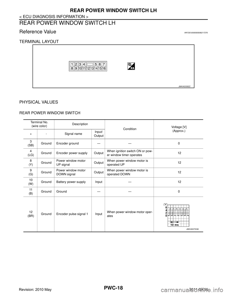
REAR POWER WINDOW SWITCH LH
Reference Value INFOID:0000000006217276
TERMINAL LAYOUT
PHYSICAL VALUES
REAR POWER WINDOW SWITCH
JMKIA3330ZZ
Te r m i n a l N o .(wire color) Description
ConditionVoltage [V]
(Approx.)
+ - Signal name Input/
Output
3
(SB) Ground Encoder ground — — 0
4
(LG) Ground Encoder power supply Output When ignition switch ON or pow-
er window timer operates
12
8
(Y) Ground
Power window motor
UP signal Output
When power window motor is
operated UP 12
9
(G) Ground Power window motor
DOWN signal OutputWhen power window motor is
operated DOWN 12
10
(W) Ground Battery power supply Input — 12
11
(B) Ground Ground — — 0
12
(BR) Ground Encoder pulse signal 1 Input When power window motor oper-
ates
JMKIA0070GB
Revision: 2010 May2011 QX56
Page 4104 of 5598
REAR POWER WINDOW SWITCH LHPWC-19
< ECU DIAGNOSIS INFORMATION >
C
DE
F
G H
I
J
L
M A
B
PWC
N
O P
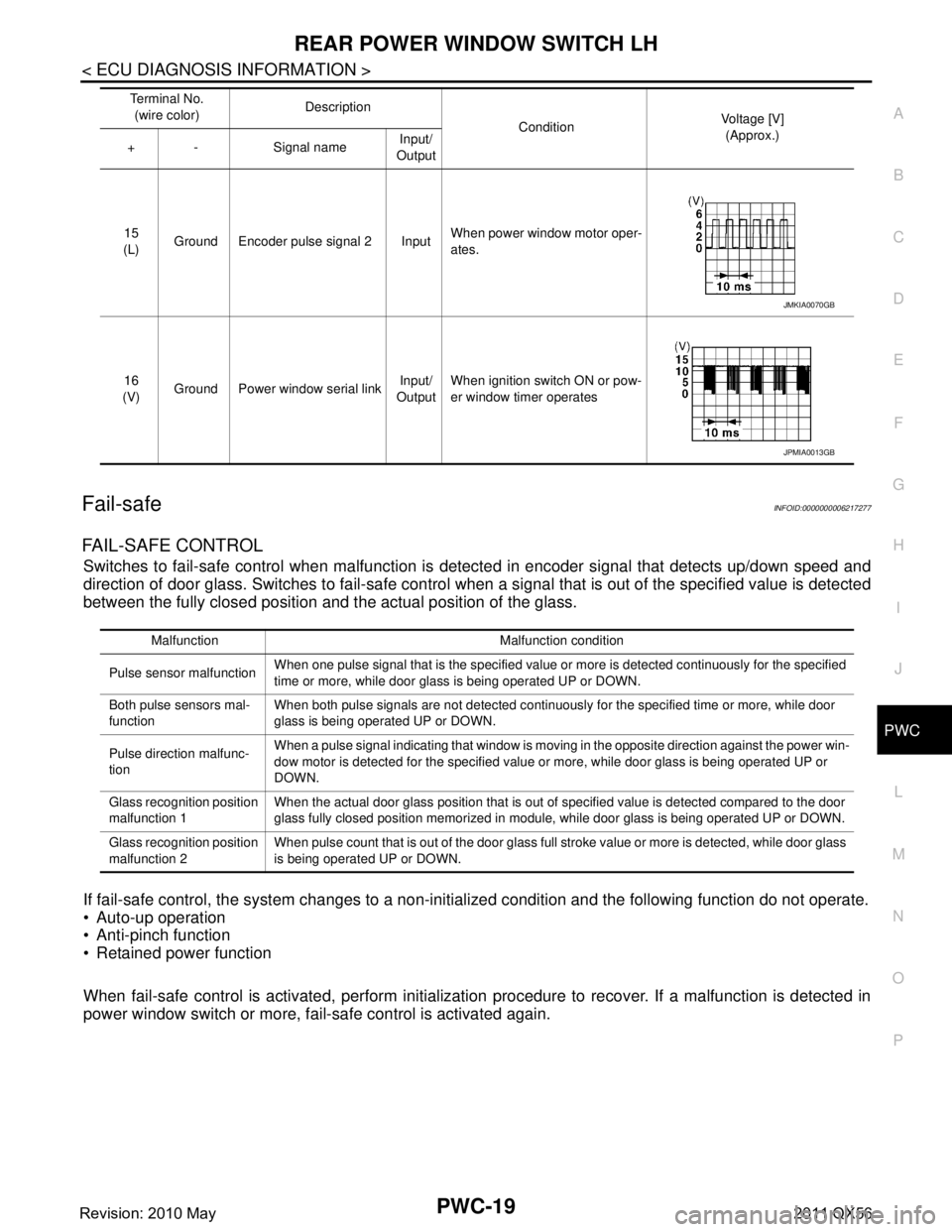
Fail-safeINFOID:0000000006217277
FAIL-SAFE CONTROL
Switches to fail-safe control when malfunction is detected in encoder signal that detects up/down speed and
direction of door glass. Switches to fail-safe control w hen a signal that is out of the specified value is detected
between the fully closed position and the actual position of the glass.
If fail-safe control, the system changes to a non-in itialized condition and the following function do not operate.
Auto-up operation
Anti-pinch function
Retained power function
When fail-safe control is activated, perform initialization procedure to recover. If a malfunction is detected in
power window switch or more, fail-safe control is activated again.
15
(L) Ground Encoder pulse signal 2 Input When power window motor oper-
ates.
16
(V) Ground Power window serial link Input/
Output When ignition switch ON or pow-
er window timer operates
Te r m i n a l N o .
(wire color) Description
ConditionVoltage [V]
(Approx.)
+ - Signal name Input/
Output
JMKIA0070GB
JPMIA0013GB
Malfunction Malfunction condition
Pulse sensor malfunction When one pulse signal that is the specified value or more is detected continuously for the specified
time or more, while door glass is being operated UP or DOWN.
Both pulse sensors mal-
function When both pulse signals are not detected continuously for the specified time or more, while door
glass is being operated UP or DOWN.
Pulse direction malfunc-
tion When a pulse signal indicating that window is moving in the opposite direction against the power win-
dow motor is detected for the specified value or more, while door glass is being operated UP or
DOWN.
Glass recognition position
malfunction 1 When the actual door glass position that is out of specified value is detected compared to the door
glass fully closed position memorized in module, while door glass is being operated UP or DOWN.
Glass recognition position
malfunction 2 When pulse count that is out of the door glass full stroke value or more is detected, while door glass
is being operated UP or DOWN.
Revision: 2010 May2011 QX56
Page 4105 of 5598
PWC-20
< ECU DIAGNOSIS INFORMATION >
REAR POWER WINDOW SWITCH RH
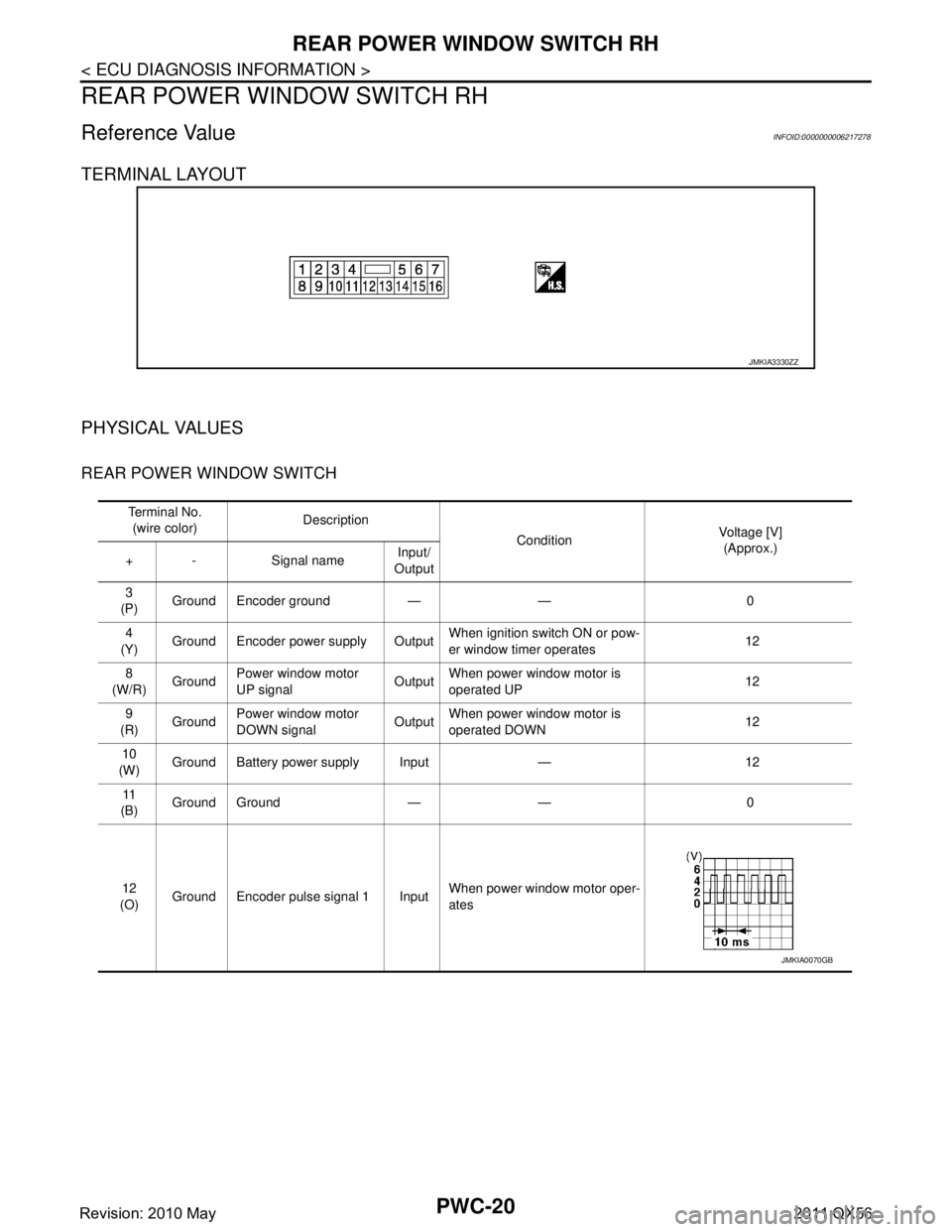
REAR POWER WINDOW SWITCH RH
Reference Value INFOID:0000000006217278
TERMINAL LAYOUT
PHYSICAL VALUES
REAR POWER WINDOW SWITCH
JMKIA3330ZZ
Te r m i n a l N o .(wire color) Description
ConditionVoltage [V]
(Approx.)
+ - Signal name Input/
Output
3
(P) Ground Encoder ground — — 0
4
(Y) Ground Encoder power supply Output When ignition switch ON or pow-
er window timer operates
12
8
(W/R) Ground
Power window motor
UP signal Output
When power window motor is
operated UP 12
9
(R) Ground Power window motor
DOWN signal OutputWhen power window motor is
operated DOWN 12
10
(W) Ground Battery power supply Input — 12
11
(B) Ground Ground — — 0
12
(O) Ground Encoder pulse signal 1 Input When power window motor oper-
ates
JMKIA0070GB
Revision: 2010 May2011 QX56
Page 4106 of 5598
REAR POWER WINDOW SWITCH RHPWC-21
< ECU DIAGNOSIS INFORMATION >
C
DE
F
G H
I
J
L
M A
B
PWC
N
O P
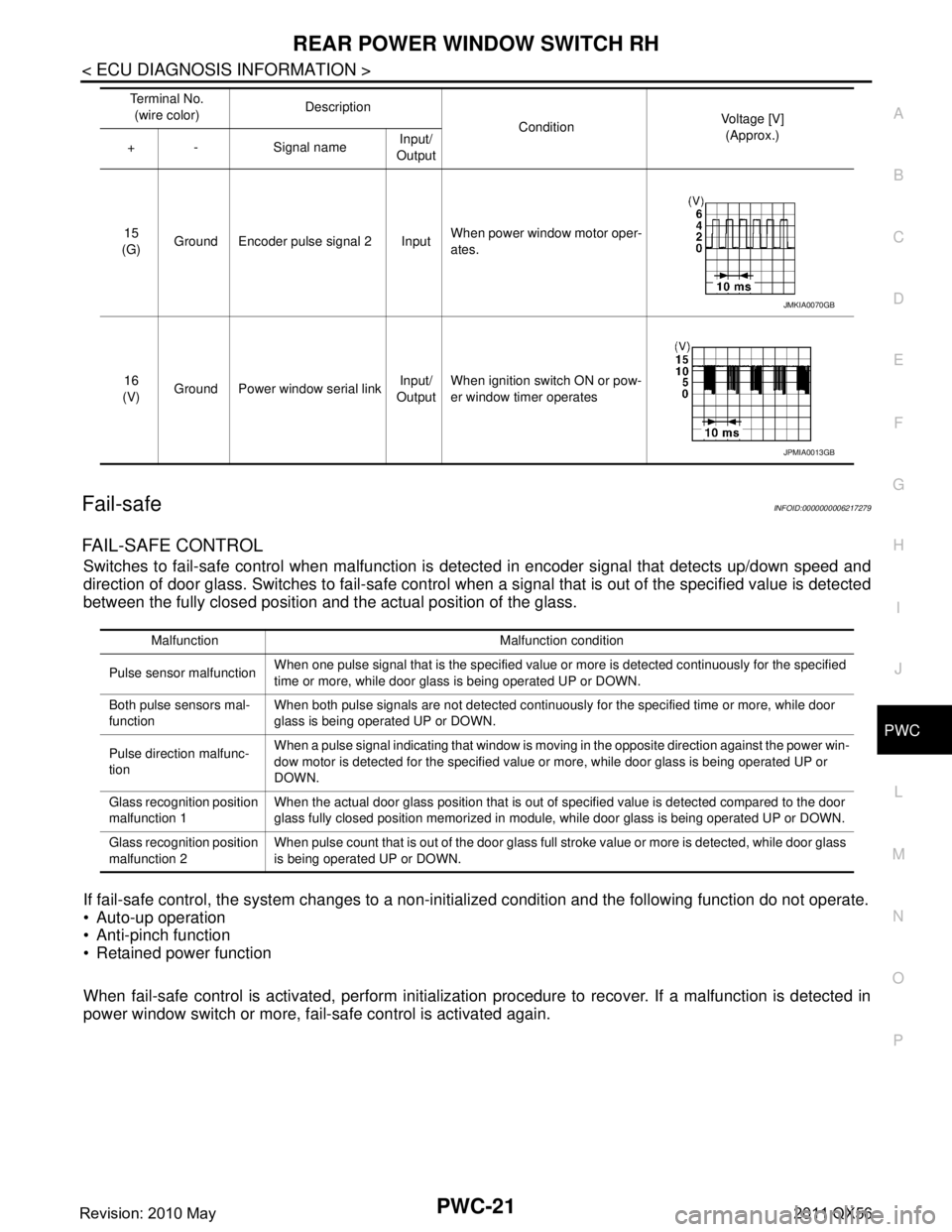
Fail-safeINFOID:0000000006217279
FAIL-SAFE CONTROL
Switches to fail-safe control when malfunction is detected in encoder signal that detects up/down speed and
direction of door glass. Switches to fail-safe control w hen a signal that is out of the specified value is detected
between the fully closed position and the actual position of the glass.
If fail-safe control, the system changes to a non-in itialized condition and the following function do not operate.
Auto-up operation
Anti-pinch function
Retained power function
When fail-safe control is activated, perform initialization procedure to recover. If a malfunction is detected in
power window switch or more, fail-safe control is activated again.
15
(G) Ground Encoder pulse signal 2 Input When power window motor oper-
ates.
16
(V) Ground Power window serial link Input/
Output When ignition switch ON or pow-
er window timer operates
Te r m i n a l N o .
(wire color) Description
ConditionVoltage [V]
(Approx.)
+ - Signal name Input/
Output
JMKIA0070GB
JPMIA0013GB
Malfunction Malfunction condition
Pulse sensor malfunction When one pulse signal that is the specified value or more is detected continuously for the specified
time or more, while door glass is being operated UP or DOWN.
Both pulse sensors mal-
function When both pulse signals are not detected continuously for the specified time or more, while door
glass is being operated UP or DOWN.
Pulse direction malfunc-
tion When a pulse signal indicating that window is moving in the opposite direction against the power win-
dow motor is detected for the specified value or more, while door glass is being operated UP or
DOWN.
Glass recognition position
malfunction 1 When the actual door glass position that is out of specified value is detected compared to the door
glass fully closed position memorized in module, while door glass is being operated UP or DOWN.
Glass recognition position
malfunction 2 When pulse count that is out of the door glass full stroke value or more is detected, while door glass
is being operated UP or DOWN.
Revision: 2010 May2011 QX56
Page 4160 of 5598

PWO
PWO-1
ELECTRICAL & POWER CONTROL
C
DE
F
G H
I
J
K L
B
SECTION PWO
A
O P
N
CONTENTS
POWER OUTLET
POWER SOCKET
PRECAUTION ................ ...............................
3
PRECAUTIONS .............................................. .....3
Precaution for Supplemental Restraint System
(SRS) "AIR BAG" and "SEAT BELT PRE-TEN-
SIONER" ............................................................. ......
3
SYSTEM DESCRIPTION ..............................4
COMPONENT PARTS ................................... .....4
Component Parts Location .................................. ......4
WIRING DIAGRAM .......................................5
POWER SOCKET .......................................... .....5
Wiring Diagram ................................................... ......5
REMOVAL AND INSTALLATION ...............10
POWER SOCKET .......................................... ....10
FRONT POWER SOCKET .................................... ....10
FRONT POWER SOCKET : Exploded View ...........10
FRONT POWER SOCKET : Removal and Instal-
lation ........................................................................
10
CONSOLE POWER SOCKET (CUP HOLDER) .... ....10
CONSOLE POWER SOCKET (CUP HOLDER) :
Exploded View ........................................................
10
CONSOLE POWER SOCKET (CUP HOLDER) :
Removal and Installation .........................................
10
CONSOLE POWER SOCKET (REAR) ................. ....11
CONSOLE POWER SOCKET (REAR) : Exploded
View ........................................................................
11
CONSOLE POWER SOCKET (REAR) : Removal
and Installation ........................................................
11
LUGGAGE ROOM POWER SOCKET .................. ....11
LUGGAGE ROOM POWER SOCKET : Exploded
View ........................................................................
12
LUGGAGE ROOM POWER SOCKET : Removal
and Installation .................................................... ....
12
AC 120 V OUTLET
PRECAUTION ............... ...............................
13
PRECAUTIONS .................................................13
Precaution for Supplemental Restraint System
(SRS) "AIR BAG" and "SEAT BELT PRE-TEN-
SIONER" ............................................................. ....
13
SYSTEM DESCRIPTION .............................14
COMPONENT PARTS ......................................14
Component Parts Location .................................. ....14
Component Description ...........................................14
Inverter Unit .............................................................14
AC120 V Outlet Main Switch ...................................14
AC120 V Outlet ........................................................14
SYSTEM ............................................................15
System Description .............................................. ....15
Fail-safe ...................................................................15
ECU DIAGNOSIS INFORMATION ..............16
INVERTER UNIT ...............................................16
Reference Value .................................................. ....16
Fail-safe ...................................................................17
WIRING DIAGRAM ......................................18
AC 120 V POWER OUTLET .............................18
Wiring Diagram .................................................... ....18
BASIC INSPECTION ...................................21
DIAGNOSIS AND REPAIR WORK FLOW .......21
Work Flow ............................................................ ....21
DTC/CIRCUIT DIAGNOSIS .........................23
POWER SUPPLY AND GROUND CIRCUIT ....23
Revision: 2010 May2011 QX56
Page 4175 of 5598
![INFINITI QX56 2011 Factory Service Manual
PWO-16
< ECU DIAGNOSIS INFORMATION >[AC 120 V OUTLET]
INVERTER UNIT
ECU DIAGNOSIS INFORMATION
INVERTER UNIT
Reference ValueINFOID:0000000006257074
TERMINAL LAYOUT
PHYSICAL VALUES
JSMIA0395ZZ
Te r m i INFINITI QX56 2011 Factory Service Manual
PWO-16
< ECU DIAGNOSIS INFORMATION >[AC 120 V OUTLET]
INVERTER UNIT
ECU DIAGNOSIS INFORMATION
INVERTER UNIT
Reference ValueINFOID:0000000006257074
TERMINAL LAYOUT
PHYSICAL VALUES
JSMIA0395ZZ
Te r m i](/manual-img/42/57033/w960_57033-4174.png)
PWO-16
< ECU DIAGNOSIS INFORMATION >[AC 120 V OUTLET]
INVERTER UNIT
ECU DIAGNOSIS INFORMATION
INVERTER UNIT
Reference ValueINFOID:0000000006257074
TERMINAL LAYOUT
PHYSICAL VALUES
JSMIA0395ZZ
Te r m i n a l N o .
(Wire color) Description
Condition Va l u e
(Approx.)
+ − Signal name Input/
Output
1
(R) 5
(G) AC 120 V output Output Ignition
switch
ON When AC 120 V outlet
main switch OFF
0 V
When AC 120 V outlet
main switch ON
(When using circuit tester) AC 120 V
When AC 120 V outlet
main switch ON
(When using oscilloscope) Reference value
AC 120 V
4
(G/R) Ground Battery power supply Input Ignition switch OFF Battery power supply
5
(G) 1
(R) AC 120 V output Output Ignition
switch ON When AC 120 V outlet
main switch OFF
0 V
When AC 120 V outlet
main switch ON
(When using circuit tester) AC 120 V
When AC 120 V outlet
main switch ON
(When using oscilloscope) Reference value
AC 120 V
JSMIA0397GB
JSMIA0397GB
Revision: 2010 May2011 QX56
Page 4176 of 5598
![INFINITI QX56 2011 Factory Service Manual
PWO
INVERTER UNITPWO-17
< ECU DIAGNOSIS INFORMATION > [AC 120 V OUTLET]
C
D
E
F
G H
I
J
K L
B A
O P
N
CAUTION:
To measure AC 120 V output signal, always use th
e circuit tester or oscilloscope AC r INFINITI QX56 2011 Factory Service Manual
PWO
INVERTER UNITPWO-17
< ECU DIAGNOSIS INFORMATION > [AC 120 V OUTLET]
C
D
E
F
G H
I
J
K L
B A
O P
N
CAUTION:
To measure AC 120 V output signal, always use th
e circuit tester or oscilloscope AC r](/manual-img/42/57033/w960_57033-4175.png)
PWO
INVERTER UNITPWO-17
< ECU DIAGNOSIS INFORMATION > [AC 120 V OUTLET]
C
D
E
F
G H
I
J
K L
B A
O P
N
CAUTION:
To measure AC 120 V output signal, always use th
e circuit tester or oscilloscope AC range.
Never allow the probes to contact each other.
Because of modified sine wave output of the AC 120 V output signal, voltage cannot be measured
accurately without using a circuit tester that can measure true RMS (root mean square).
Fail-safeINFOID:0000000006257075
When a malfunction listed below occurs, the inverter unit turns OFF the AC 120 V outlet main switch indicator
and stops the output by operating the fail-safe.
6
(W)
Ground AC 120 V outlet main
switch
InputIgnition
switch ON When AC 120 V outlet
main switch OFF
0 V
When AC 120 V outlet
main switch ON 12 V
7
(O) AC 120 V outlet main
switch indicator
OutputIgnition
switch ON When AC 120 V outlet
main switch OFF
0 V
When AC 120 V outlet
main switch ON 5.2 V
8
(G/Y) Ground — Ignition switch ON 0 V
Te r m i n a l N o .
(Wire color) Description
Condition Va l u e
(Approx.)
+ − Signal name Input/
Output
Malfunction item Fail-safe condition Fail-safe cancellation condition
Inverter unit is overheat-
ed When the inverter unit is overheated, the output
stops to protect the inverter unit. After the inverter unit temperature is lowered, the
AC 120 V outlet main switch ON
⇒ OFF ⇒ ON op-
eration allows normal return.
Inverter unit power sup-
ply voltage is 11.5 V or
less When inverter unit input voltage is lowered, the out-
put stops to protect the battery from running out.
Automatic normal return wh
en inverter unit power
supply voltage reaches 11.5 V - 16 V.
Inverter unit power sup-
ply voltage is 16 V - 18 V When inverter unit input voltage reaches 16 V - 18 V,
the output stops to protect the inverter unit. Automatic normal return wh
en inverter unit power
supply voltage reaches 11.5 V - 16 V.
Inverter unit power sup-
ply voltage is 18 V or
more When inverter unit input voltage reaches 18 V or
more, the output stops to protect the inverter unit. After the inverter unit power supply voltage reaches
11.5 V - 16 V, the AC 120 V outlet main switch ON
⇒
OFF ⇒ ON operation allows normal return.
Inverter unit output cur-
rent is 2.8 A or more When inverter unit output current reaches 2.8 A or
more, the output stops to prevent over current. (e.g.
connecting an electric appliance exceeding rated
output) Automatic normal return wh
en inverter output cur-
rent reaches 2.8 A.
Inverter unit output signal
(AC 120 V output signal)
is shorted When inverter unit output signal is shorted, the out-
put stops. After recovering from inverter unit output signal
short, the AC 120 V outlet main switch ON
⇒ OFF
⇒ ON operation allows normal return.
Revision: 2010 May2011 QX56
Page 4210 of 5598
RAX-14
< REMOVAL AND INSTALLATION >
REAR DRIVE SHAFT
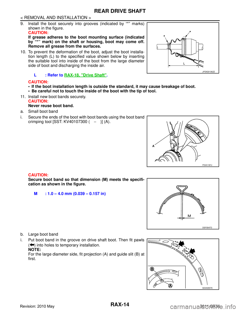
9. Install the boot securely into grooves (indicated by “*” marks)shown in the figure.
CAUTION:
If grease adheres to the boot mounting surface (indicated
by “*” mark) on the shaft or housing, boot may come off.
Remove all grease from the surfaces.
10. To prevent the deformation of the boot, adjust the boot installa- tion length (L) to the specified value shown below by inserting
the suitable tool into inside of the boot from the large diameter
side of boot and discharging the inside air.
CAUTION:
If the boot installation length is outsid e the standard, it may cause breakage of boot.
Be careful not to touch the inside of the boot with the tip of tool.
11. Install new boot bands securely. CAUTION:
Never reuse boot band.
a. Small boot band
i. Secure the ends of the boot with boot bands using the boot band crimping tool [SST: KV40107300 ( −)] (A).
CAUTION:
Secure boot band so that dimension (M) meets the specifi-
cation as shown in the figure.
b. Large boot band
i. Put boot band in the groove on drive shaft boot. Then fit pawls ( ) into holes to temporary installation.
NOTE:
For the large diameter side, fit projection (A) and guide slit (B) at
first.L: Refer to
RAX-18, "
Drive Shaft".
JPDIG0136ZZ
PDIA1187J
M : 1.0 – 4.0 mm (0.039 – 0.157 in)
DSF0047D
SDIA3557E
Revision: 2010 May2011 QX56