2011 INFINITI QX56 ECU
[x] Cancel search: ECUPage 4211 of 5598
REAR DRIVE SHAFTRAX-15
< REMOVAL AND INSTALLATION >
CEF
G H
I
J
K L
M A
B
RAX
N
O P
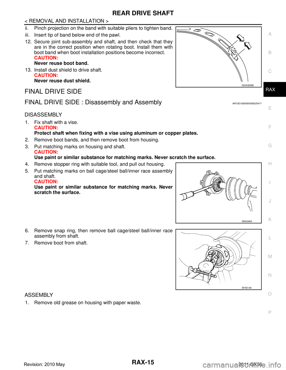
ii. Pinch projection on the band with suitable pliers to tighten band.
iii. Insert tip of band below end of the pawl.
12. Secure joint sub-assembly and shaft, and then check that they are in the correct position when rotating boot. Install them with
boot band when boot installation positions become incorrect.
CAUTION:
Never reuse boot band.
13. Install dust shield to drive shaft. CAUTION:
Never reuse dust shield.
FINAL DRIVE SIDE
FINAL DRIVE SIDE : Dis assembly and AssemblyINFOID:0000000006225471
DISASSEMBLY
1. Fix shaft with a vise.
CAUTION:
Protect shaft when fixing with a vi se using aluminum or copper plates.
2. Remove boot bands, and then remove boot from housing.
3. Put matching marks on housing and shaft. CAUTION:
Use paint or similar substance for matc hing marks. Never scratch the surface.
4. Remove stopper ring with suitable tool, and pull out housing.
5. Put matching marks on ball cage/steel ball/inner race assembly and shaft.
CAUTION:
Use paint or similar substance for matching marks. Never
scratch the surface.
6. Remove snap ring, then remove ball cage/steel ball/inner race assembly from shaft.
7. Remove boot from shaft.
ASSEMBLY
1. Remove old grease on housing with paper waste.
SDIA3558E
SRA249A
SFA514A
Revision: 2010 May2011 QX56
Page 4212 of 5598
RAX-16
< REMOVAL AND INSTALLATION >
REAR DRIVE SHAFT
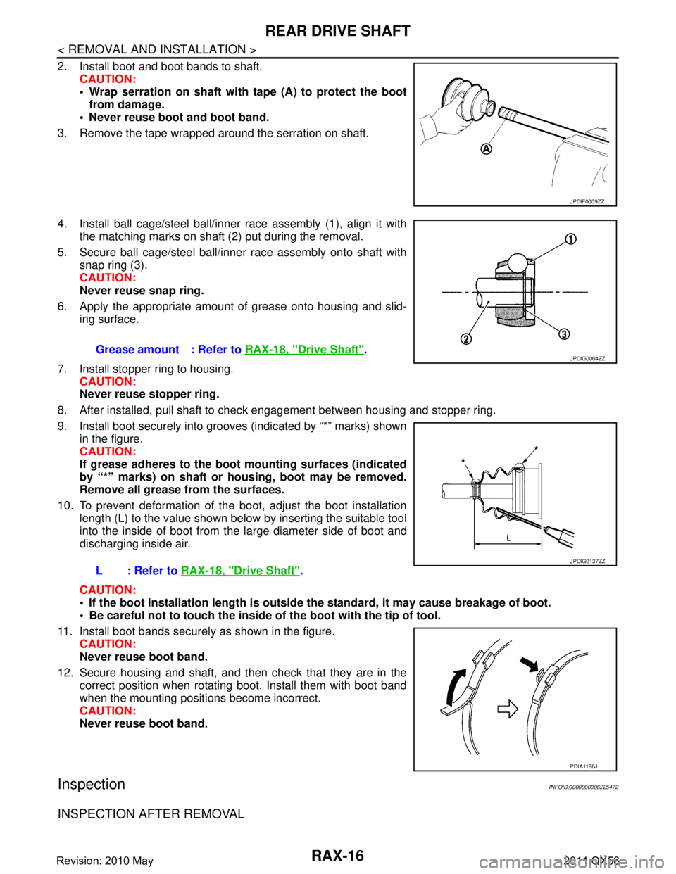
2. Install boot and boot bands to shaft.CAUTION:
Wrap serration on shaft with tape (A) to protect the bootfrom damage.
Never reuse boot and boot band.
3. Remove the tape wrapped around the serration on shaft.
4. Install ball cage/steel ball/inner race assembly (1), align it with the matching marks on shaft (2) put during the removal.
5. Secure ball cage/steel ball/inner race assembly onto shaft with snap ring (3).
CAUTION:
Never reuse snap ring.
6. Apply the appropriate amount of grease onto housing and slid- ing surface.
7. Install stopper ring to housing. CAUTION:
Never reuse stopper ring.
8. After installed, pull shaft to check engagement between housing and stopper ring.
9. Install boot securely into grooves (indicated by “*” marks) shown in the figure.
CAUTION:
If grease adheres to the boot mounting surfaces (indicated
by “*” marks) on shaft or housing, boot may be removed.
Remove all grease from the surfaces.
10. To prevent deformation of the boot, adjust the boot installation
length (L) to the value shown below by inserting the suitable tool
into the inside of boot from the large diameter side of boot and
discharging inside air.
CAUTION:
If the boot installation length is outsid e the standard, it may cause breakage of boot.
Be careful not to touch the inside of the boot with the tip of tool.
11. Install boot bands securely as shown in the figure. CAUTION:
Never reuse boot band.
12. Secure housing and shaft, and then check that they are in the correct position when rotating boot. Install them with boot band
when the mounting positi ons become incorrect.
CAUTION:
Never reuse boot band.
InspectionINFOID:0000000006225472
INSPECTION AFTER REMOVAL
JPDIF0009ZZ
Grease amount : Refer to RAX-18, "Drive Shaft".
L: Refer to RAX-18, "
Drive Shaft".
JPDIG0004ZZ
JPDIG0137ZZ
PDIA1188J
Revision: 2010 May2011 QX56
Page 4215 of 5598
RF-1
BODY EXTERIOR, DOORS, ROOF & VEHICLE SECURITY
C
D
E
F
G H
I
J
L
M
SECTION RF
A
B
RF
N
O P
CONTENTS
ROOF
PRECAUTION ................ ...............................3
PRECAUTIONS .............................................. .....3
Precaution for Supplemental Restraint System
(SRS) "AIR BAG" and "SEAT BELT PRE-TEN-
SIONER" ............................................................. ......
3
PREPARATION ............................................4
PREPARATION .............................................. .....4
Commercial Service Tool .................................... ......4
SYSTEM DESCRIPTION ..............................5
COMPONENT PARTS ................................... .....5
Component Parts Location ................................ ......5
Component Description ............................................5
SYSTEM ..............................................................6
System Diagram ................................................. ......6
System Description ...................................................6
ECU DIAGNOSIS INFORMATION ...............7
BCM (BODY CONTROL MODULE) ............... .....7
List of ECU Reference ........................................ ......7
SUNROOF SYSTEM ...................................... .....8
Reference Value ................................................. ......8
WIRING DIAGRAM .......................................9
SUNROOF MOTOR ASSEMBLY ................... .....9
Wiring Diagram ................................................... ......9
BASIC INSPECTION ...................................16
DIAGNOSIS AND REPAIR WORKFLOW ..... ....16
WorkFlow ............................................................ ....16
INSPECTION AND ADJUSTMENT ....................17
ADDITIONAL SERVICE WHEN REPLACING
CONTROL UNIT .................................................... ....
17
ADDITIONAL SERVICE WHEN REPLACING
CONTROL UNIT : Description .................................
17
ADDITIONAL SERVICE WHEN REPLACING
CONTROL UNIT : Special Repair Requirement ......
17
DTC/CIRCUIT DIAGNOSIS .........................18
POWER SUPPLY AND GROUND CIRCUIT ....18
Diagnosis Procedure .......................................... ....18
VEHICLE SPEED SIGNAL CIRCUIT ................20
Component Function Check ..................................20
Diagnosis Procedure ..............................................20
SUNROOF SWITCH ..........................................21
Component Function Check ..................................21
Diagnosis Procedure ..............................................21
Component Inspection .............................................22
SYMPTOM DIAGNOSIS ..............................23
SUNROOF DOES NOT OPERATE PROPER-
LY ......................................................................
23
Description ........................................................... ....23
Diagnosis Procedure ...............................................23
SUNROOF DOES NOT OPERATE ANTI-
PINCH FUNCTION ............................................
24
Diagnosis Procedure ........................................... ....24
RETAINED POWER OPERATION DOES NOT
OPERATE PROPERLY .....................................
25
Diagnosis Procedure ...............................................25
SQUEAK AND RATTLE TROUBLE DIAG-
NOSES ..............................................................
26
Work Flow ................................................................26
Inspection Procedure ...............................................28
Diagnostic Worksheet ..............................................30
REMOVAL AND INSTALLATION ...............32
GLASS LID ........................................................32
Revision: 2010 May2011 QX56
Page 4221 of 5598
BCM (BODY CONTROL MODULE)RF-7
< ECU DIAGNOSIS INFORMATION >
C
DE
F
G H
I
J
L
M A
B
RF
N
O P
ECU DIAGNOSIS INFORMATION
BCM (BODY CONTROL MODULE)
List of ECU ReferenceINFOID:0000000006141226
ECU Reference
BCM BCS-33, "
Reference Value"
BCS-54, "Fail-safe"
BCS-57, "DTCIndex"
Revision: 2010 May2011 QX56
Page 4222 of 5598
RF-8
< ECU DIAGNOSIS INFORMATION >
SUNROOF SYSTEM
SUNROOF SYSTEM
Reference ValueINFOID:0000000006141227
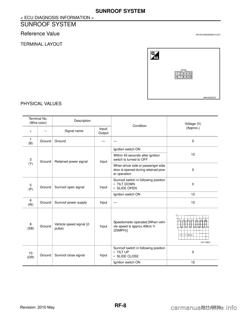
TERMINAL LAYOUT
PHYSICAL VALUES
JMKIA2225ZZ
Te r m i n a l N o .(Wire color) Description
ConditionVoltage (V)
(Approx.)
+ – Signal name Input/
Output
1
(B) Ground Ground — — 0
3
(Y) Ground Retained power signal Input Ignition switch ON
12
Within 45 seconds after ignition
switch is turned to OFF
When driver side or passenger side
door is opened during retained pow-
er operation 0
5
(P) Ground Sunroof open signal Input Sunroof switch in following position
TILT DOWN
SLIDE OPEN
0
Ignition switch ON 12
6
(W) Ground Sunroof power supply Input — 12
8
(SB) Ground Vehicle speed signal (2-
pulse)
InputSpeedometer operated [When vehi-
cle speed is approx.40km/ h
(25MPH)]
10
(GR) Ground Sunroof close signal Input Sunroof switch in following position
TILT UP
SLIDE CLOSE
0
Ignition switch ON 12
ELF1080D
Revision: 2010 May2011 QX56
Page 4235 of 5598
SUNROOF SWITCHRF-21
< DTC/CIRCUIT DIAGNOSIS >
C
DE
F
G H
I
J
L
M A
B
RF
N
O P
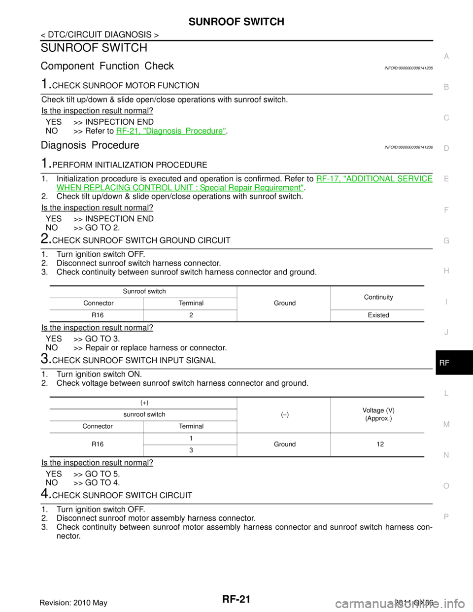
SUNROOF SWITCH
Component Function CheckINFOID:0000000006141235
1.CHECK SUNROOF MOTOR FUNCTION
Check tilt up/down & slide open/close operations with sunroof switch.
Is the inspection result normal?
YES >> INSPECTION END
NO >> Refer to RF-21, "
DiagnosisProcedure".
Diagnosis ProcedureINFOID:0000000006141236
1.PERFORM INITIALIZATION PROCEDURE
1. Initialization procedure is executed and operation is confirmed. Refer to RF-17, "
ADDITIONAL SERVICE
WHEN REPLACING CONTROL UNIT : Special Repair Requirement".
2. Check tilt up/down & slide open/close operations with sunroof switch.
Is the inspection result normal?
YES >> INSPECTION END
NO >> GO TO 2.
2.CHECK SUNROOF SWITCH GROUND CIRCUIT
1. Turn ignition switch OFF.
2. Disconnect sunroof switch harness connector.
3. Check continuity between sunroof switch harness connector and ground.
Is the inspection result normal?
YES >> GO TO 3.
NO >> Repair or replace harness or connector.
3.CHECK SUNROOF SWITCH INPUT SIGNAL
1. Turn ignition switch ON.
2. Check voltage between sunroof switch harness connector and ground.
Is the inspection result normal?
YES >> GO TO 5.
NO >> GO TO 4.
4.CHECK SUNROOF SWITCH CIRCUIT
1. Turn ignition switch OFF.
2. Disconnect sunroof motor assembly harness connector.
3. Check continuity between sunroof motor assemb ly harness connector and sunroof switch harness con-
nector.
Sunroof switch
GroundContinuity
Connector Terminal
R16 2 Existed
(+) (− ) Voltage (V)
(Approx.)
sunroof switch
Connector Terminal
R16 1
Ground 12
3
Revision: 2010 May2011 QX56
Page 4237 of 5598
SUNROOF DOES NOT OPERATE PROPERLYRF-23
< SYMPTOM DIAGNOSIS >
C
DE
F
G H
I
J
L
M A
B
RF
N
O P
SYMPTOM DIAGNOSIS
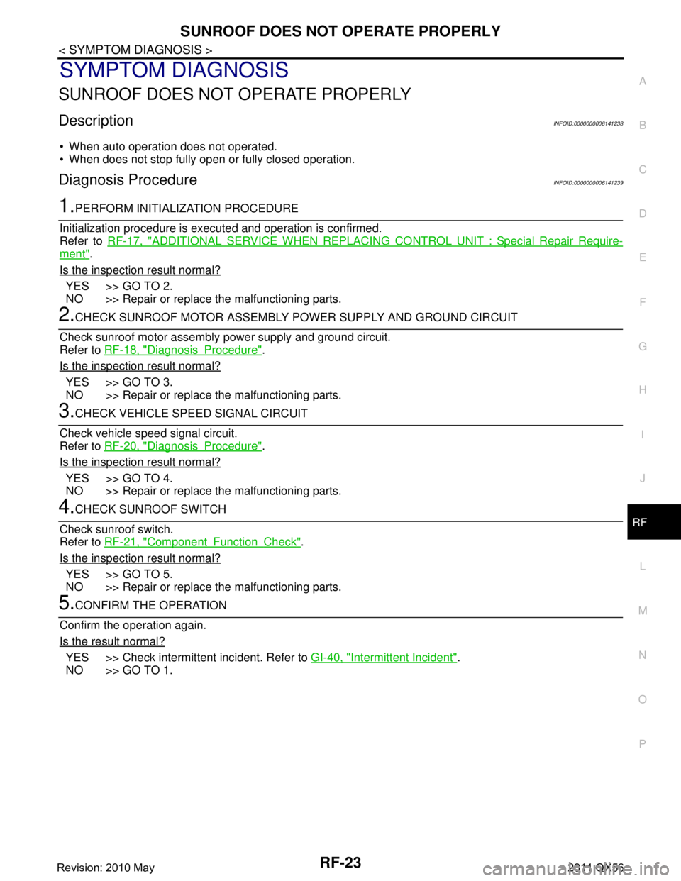
SUNROOF DOES NOT OPERATE PROPERLY
DescriptionINFOID:0000000006141238
When auto operation does not operated.
When does not stop fully open or fully closed operation.
Diagnosis ProcedureINFOID:0000000006141239
1.PERFORM INITIALIZATION PROCEDURE
Initialization procedure is executed and operation is confirmed.
Refer to RF-17, "
ADDITIONAL SERVICE WHEN REPLACING CO NTROL UNIT : Special Repair Require-
ment".
Is the inspection result normal?
YES >> GO TO 2.
NO >> Repair or replace the malfunctioning parts.
2.CHECK SUNROOF MOTOR ASSEMBLY POWER SUPPLY AND GROUND CIRCUIT
Check sunroof motor assembly power supply and ground circuit.
Refer to RF-18, "
DiagnosisProcedure".
Is the inspection result normal?
YES >> GO TO 3.
NO >> Repair or replace the malfunctioning parts.
3.CHECK VEHICLE SPEED SIGNAL CIRCUIT
Check vehicle speed signal circuit.
Refer to RF-20, "
DiagnosisProcedure".
Is the inspection result normal?
YES >> GO TO 4.
NO >> Repair or replace the malfunctioning parts.
4.CHECK SUNROOF SWITCH
Check sunroof switch.
Refer to RF-21, "
ComponentFunctionCheck".
Is the inspection result normal?
YES >> GO TO 5.
NO >> Repair or replace the malfunctioning parts.
5.CONFIRM THE OPERATION
Confirm the operation again.
Is the result normal?
YES >> Check intermittent incident. Refer to GI-40, "Intermittent Incident".
NO >> GO TO 1.
Revision: 2010 May2011 QX56
Page 4241 of 5598
SQUEAK AND RATTLE TROUBLE DIAGNOSESRF-27
< SYMPTOM DIAGNOSIS >
C
DE
F
G H
I
J
L
M A
B
RF
N
O P
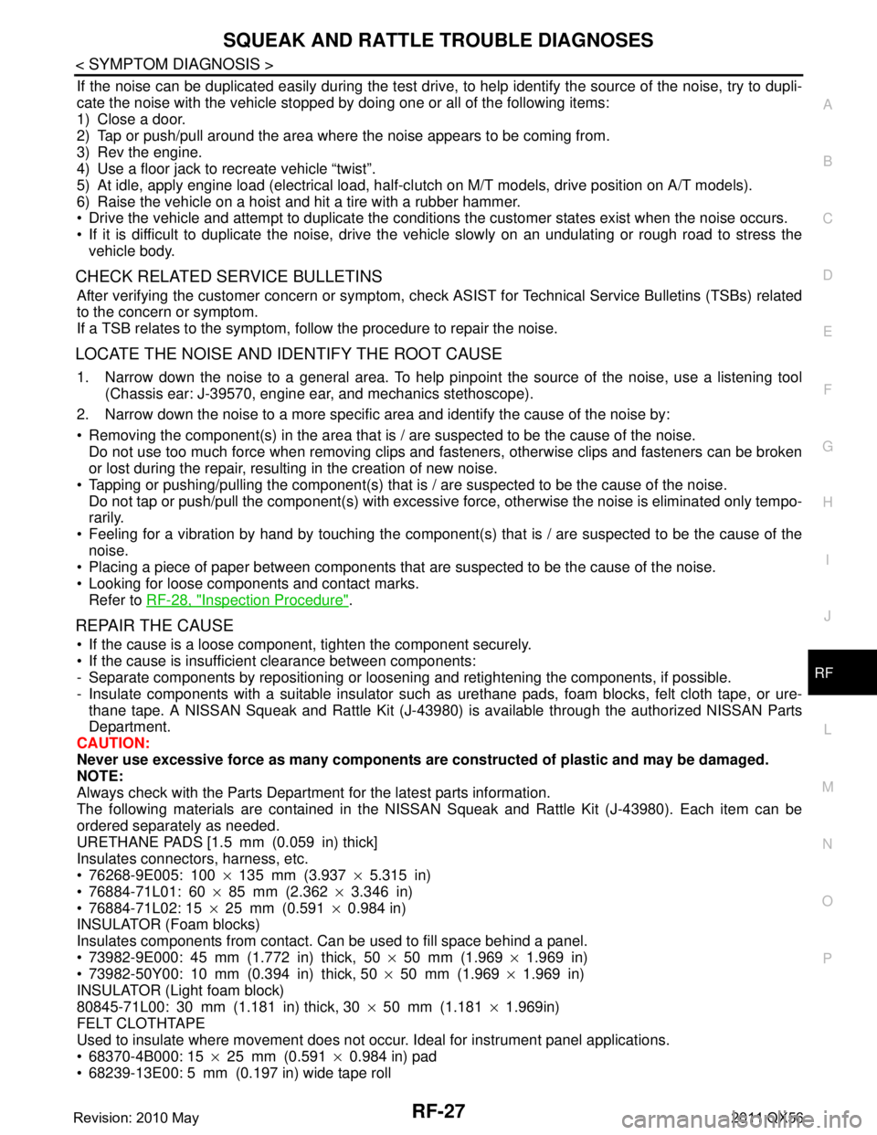
If the noise can be duplicated easily during the test drive, to help identify the source of the noise, try to dupli-
cate the noise with the vehicle stopped by doing one or all of the following items:
1) Close a door.
2) Tap or push/pull around the area where the noise appears to be coming from.
3) Rev the engine.
4) Use a floor jack to recreate vehicle “twist”.
5) At idle, apply engine load (electrical load, half-cl utch on M/T models, drive position on A/T models).
6) Raise the vehicle on a hoist and hit a tire with a rubber hammer.
Drive the vehicle and attempt to duplicate the conditions the customer states exist when the noise occurs.
If it is difficult to duplicate the noise, drive the vehicle slowly on an undulating or rough road to stress the vehicle body.
CHECK RELATED SERVICE BULLETINS
After verifying the customer concern or symptom, che ck ASIST for Technical Service Bulletins (TSBs) related
to the concern or symptom.
If a TSB relates to the symptom, follow the procedure to repair the noise.
LOCATE THE NOISE AND IDENTIFY THE ROOT CAUSE
1. Narrow down the noise to a general area. To help pinpoint the source of the noise, use a listening tool
(Chassis ear: J-39570, engine ear, and mechanics stethoscope).
2. Narrow down the noise to a more specific area and identify the cause of the noise by:
Removing the component(s) in the area that is / are suspected to be the cause of the noise.
Do not use too much force when removing clips and fasteners, otherwise clips and fasteners can be broken
or lost during the repair, resulting in the creation of new noise.
Tapping or pushing/pulling the component(s) that is / are suspected to be the cause of the noise.
Do not tap or push/pull the component(s) with excessive force, otherwise the noise is eliminated only tempo-
rarily.
Feeling for a vibration by hand by touching the component(s ) that is / are suspected to be the cause of the
noise.
Placing a piece of paper between components that are suspected to be the cause of the noise.
Looking for loose components and contact marks. Refer to RF-28, "
Inspection Procedure".
REPAIR THE CAUSE
If the cause is a loose component, tighten the component securely.
If the cause is insufficient clearance between components:
- Separate components by repositioning or loosening and retightening the components, if possible.
- Insulate components with a suitable insulator such as urethane pads, foam blocks, felt cloth tape, or ure-
thane tape. A NISSAN Squeak and Rattle Kit (J-43980) is available through the authorized NISSAN Parts
Department.
CAUTION:
Never use excessive force as many components are constructed of plastic and may be damaged.
NOTE:
Always check with the Parts Department for the latest parts information.
The following materials are contained in the NISSA N Squeak and Rattle Kit (J-43980). Each item can be
ordered separately as needed.
URETHANE PADS [1.5 mm (0.059 in) thick]
Insulates connectors, harness, etc.
76268-9E005: 100 ×135 mm (3.937 ×5.315 in)
76884-71L01: 60 ×85 mm (2.362 ×3.346 in)
76884-71L02: 15 ×25 mm (0.591 ×0.984 in)
INSULATOR (Foam blocks)
Insulates components from contact. Can be used to fill space behind a panel.
73982-9E000: 45 mm (1.772 in) thick, 50 ×50 mm (1.969 ×1.969 in)
73982-50Y00: 10 mm (0.394 in) thick, 50 ×50 mm (1.969 ×1.969 in)
INSULATOR (Light foam block)
80845-71L00: 30 mm (1.181 in) thick, 30 ×50 mm (1.181 ×1.969in)
FELT CLOTHTAPE
Used to insulate where movement does not occur. Ideal for instrument panel applications.
68370-4B000: 15 ×25 mm (0.591 ×0.984 in) pad
68239-13E00: 5 mm (0.197 in) wide tape roll
Revision: 2010 May2011 QX56