2011 INFINITI QX56 steering
[x] Cancel search: steeringPage 3576 of 5598
![INFINITI QX56 2011 Factory Service Manual
LAN-156
< DTC/CIRCUIT DIAGNOSIS >[CAN SYSTEM (TYPE 2)]
STRG BRANCH LINE CIRCUIT
STRG BRANCH LINE CIRCUIT
Diagnosis ProcedureINFOID:0000000006256299
1.CHECK CONNECTOR
1. Turn the ignition switch OFF.
INFINITI QX56 2011 Factory Service Manual
LAN-156
< DTC/CIRCUIT DIAGNOSIS >[CAN SYSTEM (TYPE 2)]
STRG BRANCH LINE CIRCUIT
STRG BRANCH LINE CIRCUIT
Diagnosis ProcedureINFOID:0000000006256299
1.CHECK CONNECTOR
1. Turn the ignition switch OFF.](/manual-img/42/57033/w960_57033-3575.png)
LAN-156
< DTC/CIRCUIT DIAGNOSIS >[CAN SYSTEM (TYPE 2)]
STRG BRANCH LINE CIRCUIT
STRG BRANCH LINE CIRCUIT
Diagnosis ProcedureINFOID:0000000006256299
1.CHECK CONNECTOR
1. Turn the ignition switch OFF.
2. Disconnect the battery cable from the negative terminal.
3. Check the terminals and connectors of the steer ing angle sensor for damage, bend and loose connection
(unit side and connector side).
Is the inspection result normal?
YES >> GO TO 2.
NO >> Repair the terminal and connector.
2.CHECK HARNESS FOR OPEN CIRCUIT
1. Disconnect the connector of steering angle sensor.
2. Check the resistance between the steeri ng angle sensor harness connector terminals.
Is the measurement value within the specification?
YES >> GO TO 3.
NO >> Repair the steering angle sensor branch line.
3.CHECK POWER SUPPLY AND GROUND CIRCUIT
Check the power supply and the ground circuit of the steering angle sensor. Refer to BRC-53, "
Wiring Dia-
gram".
Is the inspection result normal?
YES (Present error)>>Replace the steering angle sensor. Refer to BRC-139, "Removal and Installation".
YES (Past error)>>Error was detected in the steering angle sensor branch line.
NO >> Repair the power supply and the ground circuit.
Steering angle sensor harness connector Resistance (Ω)
Connector No. Terminal No.
M30 5 2 Approx. 54 – 66
Revision: 2010 May2011 QX56
Page 3608 of 5598
![INFINITI QX56 2011 Factory Service Manual
LAN-188
< DTC/CIRCUIT DIAGNOSIS >[CAN SYSTEM (TYPE 3)]
STRG BRANCH LINE CIRCUIT
STRG BRANCH LINE CIRCUIT
Diagnosis ProcedureINFOID:0000000006256346
1.CHECK CONNECTOR
1. Turn the ignition switch OFF.
INFINITI QX56 2011 Factory Service Manual
LAN-188
< DTC/CIRCUIT DIAGNOSIS >[CAN SYSTEM (TYPE 3)]
STRG BRANCH LINE CIRCUIT
STRG BRANCH LINE CIRCUIT
Diagnosis ProcedureINFOID:0000000006256346
1.CHECK CONNECTOR
1. Turn the ignition switch OFF.](/manual-img/42/57033/w960_57033-3607.png)
LAN-188
< DTC/CIRCUIT DIAGNOSIS >[CAN SYSTEM (TYPE 3)]
STRG BRANCH LINE CIRCUIT
STRG BRANCH LINE CIRCUIT
Diagnosis ProcedureINFOID:0000000006256346
1.CHECK CONNECTOR
1. Turn the ignition switch OFF.
2. Disconnect the battery cable from the negative terminal.
3. Check the terminals and connectors of the steer ing angle sensor for damage, bend and loose connection
(unit side and connector side).
Is the inspection result normal?
YES >> GO TO 2.
NO >> Repair the terminal and connector.
2.CHECK HARNESS FOR OPEN CIRCUIT
1. Disconnect the connector of steering angle sensor.
2. Check the resistance between the steeri ng angle sensor harness connector terminals.
Is the measurement value within the specification?
YES >> GO TO 3.
NO >> Repair the steering angle sensor branch line.
3.CHECK POWER SUPPLY AND GROUND CIRCUIT
Check the power supply and the ground circuit of the steering angle sensor. Refer to BRC-53, "
Wiring Dia-
gram".
Is the inspection result normal?
YES (Present error)>>Replace the steering angle sensor. Refer to BRC-139, "Removal and Installation".
YES (Past error)>>Error was detected in the steering angle sensor branch line.
NO >> Repair the power supply and the ground circuit.
Steering angle sensor harness connector Resistance (Ω)
Connector No. Terminal No.
M30 5 2 Approx. 54 – 66
Revision: 2010 May2011 QX56
Page 3635 of 5598
![INFINITI QX56 2011 Factory Service Manual
LAN
STRG BRANCH LINE CIRCUITLAN-215
< DTC/CIRCUIT DIAGNOSIS > [CAN SYSTEM (TYPE 4)]
C
D
E
F
G H
I
J
K L
B A
O P
N
STRG BRANCH
LINE CIRCUIT
Diagnosis ProcedureINFOID:0000000006256386
1.CHECK CONNECTO INFINITI QX56 2011 Factory Service Manual
LAN
STRG BRANCH LINE CIRCUITLAN-215
< DTC/CIRCUIT DIAGNOSIS > [CAN SYSTEM (TYPE 4)]
C
D
E
F
G H
I
J
K L
B A
O P
N
STRG BRANCH
LINE CIRCUIT
Diagnosis ProcedureINFOID:0000000006256386
1.CHECK CONNECTO](/manual-img/42/57033/w960_57033-3634.png)
LAN
STRG BRANCH LINE CIRCUITLAN-215
< DTC/CIRCUIT DIAGNOSIS > [CAN SYSTEM (TYPE 4)]
C
D
E
F
G H
I
J
K L
B A
O P
N
STRG BRANCH
LINE CIRCUIT
Diagnosis ProcedureINFOID:0000000006256386
1.CHECK CONNECTOR
1. Turn the ignition switch OFF.
2. Disconnect the battery cabl e from the negative terminal.
3. Check the terminals and connectors of the steer ing angle sensor for damage, bend and loose connection
(unit side and connector side).
Is the inspection result normal?
YES >> GO TO 2.
NO >> Repair the terminal and connector.
2.CHECK HARNESS FOR OPEN CIRCUIT
1. Disconnect the connector of steering angle sensor.
2. Check the resistance between the steering angle sensor harness connector terminals.
Is the measurement value within the specification?
YES >> GO TO 3.
NO >> Repair the steering angle sensor branch line.
3.CHECK POWER SUPPLY AND GROUND CIRCUIT
Check the power supply and the ground circuit of the steering angle sensor. Refer to BRC-53, "
Wiring Dia-
gram".
Is the inspection result normal?
YES (Present error)>>Replace the steering angle sensor. Refer to BRC-139, "Removal and Installation".
YES (Past error)>>Error was detected in the steering angle sensor branch line.
NO >> Repair the power supply and the ground circuit.
Steering angle sensor harness connector Resistance (Ω)
Connector No. Terminal No.
M30 5 2 Approx. 54 – 66
Revision: 2010 May2011 QX56
Page 3666 of 5598

OIL PUMPLU-13
< REMOVAL AND INSTALLATION >
C
DE
F
G H
I
J
K L
M A
LU
NP
O
OIL PUMP
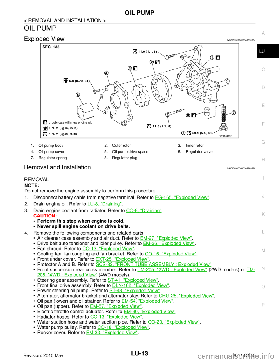
Exploded ViewINFOID:0000000006289624
Removal and InstallationINFOID:0000000006289625
REMOVAL
NOTE:
Do not remove the engine assembly to perform this procedure.
1. Disconnect battery cable from
negative terminal. Refer to PG-165, "
Exploded View".
2. Drain engine oil. Refer to LU-8, "
Draining".
3. Drain engine coolant from radiator. Refer to CO-8, "
Draining".
CAUTION:
Perform this step when engine is cold.
Never spill engine coolant on drive belts.
4. Remove the following components and related parts: Air cleaner case assembly and air duct. Refer to EM-27, "
Exploded View".
Drive belt auto tensioner and idler pulley. Refer to EM-26, "
Exploded View".
Fan shroud. Refer to CO-13, "
Exploded View".
Cooling fan, fan coupling and fan bracket. Refer to CO-16, "
Exploded View".
Front under cover. Refer to EXT-25, "
Exploded View".
Protector A and B. Refer to SCS-32, "
FRONT TUBE ASSEMBLY : Exploded View".
Front suspension rear cross member. Refer to TM-205, "
2WD : Exploded View" (2WD models) or TM-
208, "4WD : Exploded View" (4WD models).
Steering gear assembly. Refer to ST-41, "
Exploded View".
Front final drive assembly. Refer to DLN-162, "
Exploded View".
Power steering oil pump. Refer to ST-48, "
Exploded View".
Alternator, alternator bracket and alternator stay. Refer to CHG-25, "
Exploded View".
Oil pan (lower) and oil strainer. Refer to EM-54, "
Exploded View".
Oil pan (upper). Refer to EM-57, "
Exploded View".
Electric throttle control actuator. Refer to EM-30, "
Exploded View".
Radiator hoses. Refer to CO-13, "
Exploded View".
Water suction hose and water suction pipe. Refer to CO-20, "
Exploded View".
Water pump pulley. Refer to CO-18, "
Exploded View".
Rocker cover. Refer to EM-33, "
Exploded View".
WBIA0415E
1. Oil pump body 2. Outer rotor 3. Inner rotor
4. Oil pump cover 5. Oil pump drive spacer 6. Regulator valve
7. Regulator spring 8. Regulator plug
Revision: 2010 May2011 QX56
Page 3672 of 5598

MA-2
FRONT DIFFERENTIAL GEAR OIL: R180A :
Draining ..................................................................
24
FRONT DIFFERENTIAL GEAR OIL: R180A : Re-
filling .......................................................................
25
REAR DIFFERENTIAL GEAR OIL: R230 ............. ...25
REAR DIFFERENTIAL GEAR OIL: R230 : Inspec-
tion ..........................................................................
25
REAR DIFFERENTIAL GEAR OIL: R230 : Drain-
ing ...........................................................................
25
REAR DIFFERENTIAL GEAR OIL: R230 : Refill-
ing ...........................................................................
26
WHEELS (BONDING WEIGHT TYPE) .....................26
WHEELS (BONDING WEIGHT TYPE) : Adjust-
ment ..................................................................... ...
26
BRAKE FLUID LEVEL AND LEAKS ........................27
BRAKE FLUID LEVEL AND LEAKS : Inspection ...28
BRAKE LINES AND CABLES ............................... ...28
BRAKE LINES AND CABLES : Inspection .............28
BRAKE FLUID ....................................................... ...28
BRAKE FLUID : Bleeding Brake System ................28
DISC BRAKE ......................................................... ...30
DISC BRAKE : Inspection ......................................30
DISC BRAKE : Front Disc Brake ............................31
DISC BRAKE : Rear Disc Brake .............................31
STEERING GEAR AND LINKAGE ........................ ...31
STEERING GEAR AND LINKAGE : Inspection ......31
POWER STEERING FLUID AND LINES ............... ...32
POWER STEERING FLUID AND LINES : Inspec-
tion ..........................................................................
32
AXLE AND SUSPENSION PARTS ...........................32
AXLE AND SUSPENSION PARTS : Inspection .. ...32
DRIVE SHAFT ........................................................ ...33
DRIVE SHAFT : Inspection .....................................33
BODY MAINTENANCE .....................................34
LOCKS, HINGES AND HOOD LATCH .................. ...34
LOCKS, HINGES AND HOOD LATCH : Lubricat-
ing ...........................................................................
34
SEAT BELT, BUCKLES, RETRACTORS, AN-
CHORS AND ADJUSTERS ................................... ...
34
SEAT BELT, BUCKLES, RETRACTORS, AN-
CHORS AND ADJUSTERS : Inspection .................
34
SERVICE DATA AND SPECIFICATIONS
(SDS) .......... ................................................
35
SERVICE DATA AND SPECIFICATIONS
(SDS) .............................................................. ...
35
DRIVE BELTS ........................................................ ...35
DRIVE BELTS : Drive Belts ....................................35
ENGINE COOLANT ............................................... ...35
ENGINE COOLANT :
Periodical Maintenance Specification ....................
35
ENGINE OIL ........................................................... ...35
ENGINE OIL : Periodical Maintenance Specifica-
tion ..........................................................................
35
SPARK PLUG ........................................................ ...35
SPARK PLUG : Spark Plug ....................................35
ROAD WHEEL ....................................................... ...35
ROAD WHEEL : Road Wheel .................................35
Revision: 2010 May2011 QX56
Page 3674 of 5598

MA-4
< PERIODIC MAINTENANCE >
GENERAL MAINTENANCE
PERIODIC MAINTENANCE
GENERAL MAINTENANCE
Explanation of General MaintenanceINFOID:0000000006287728
General maintenance includes those items which shoul d be checked during the normal day-to-day operation
of the vehicle. They are essential if the vehicle is to continue operating properly. The owners can perform
checks and inspections themselves or have their INFINITI dealers do them.
OUTSIDE THE VEHICLE
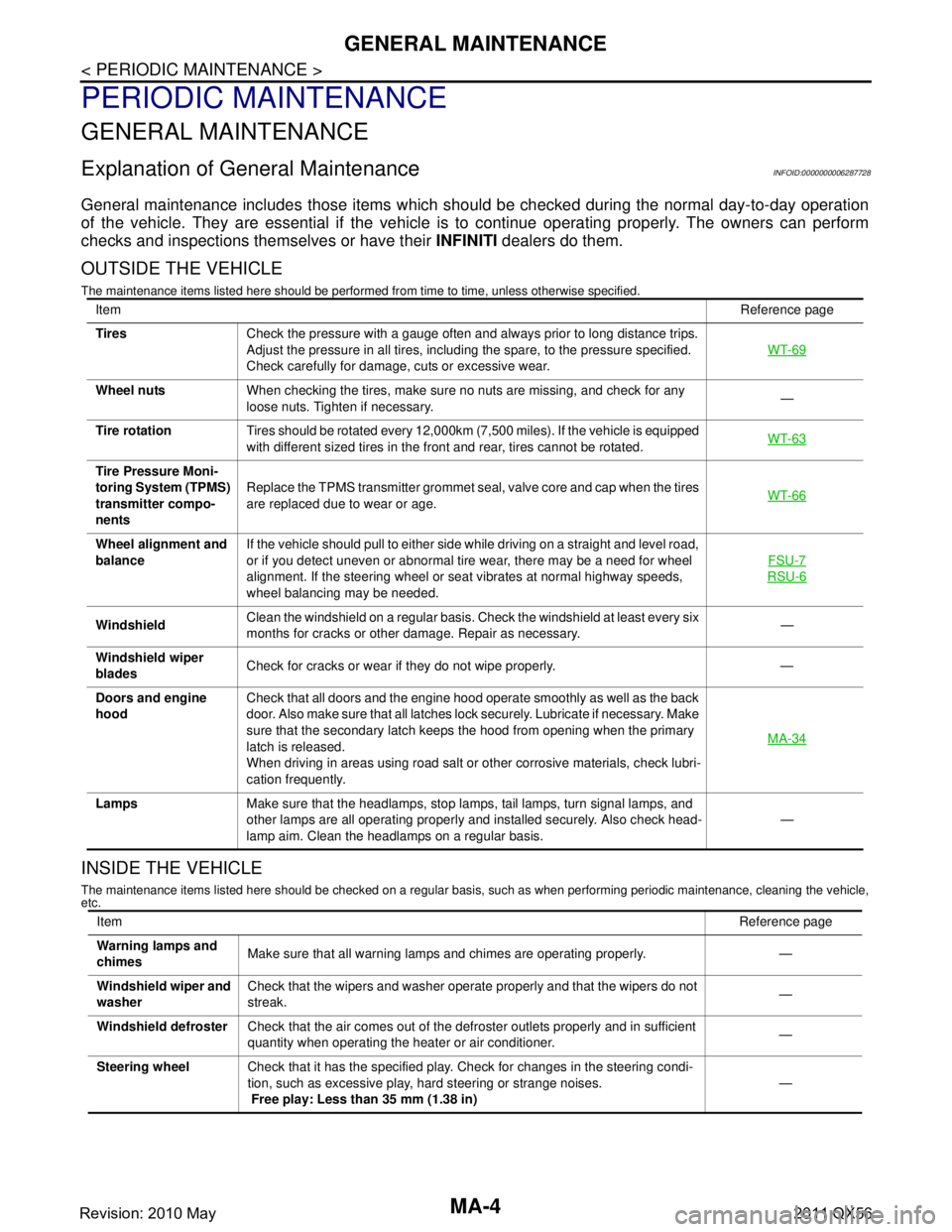
The maintenance items listed here should be performed fr om time to time, unless otherwise specified.
INSIDE THE VEHICLE
The maintenance items listed here should be checked on a regular basis, such as when performing periodic maintenance, cleaning the vehicle,
etc.
Item Reference page
Tires Check the pressure with a gauge often and always prior to long distance trips.
Adjust the pressure in all tires, including the spare, to the pressure specified.
Check carefully for damage, cuts or excessive wear. WT-69
Wheel nuts
When checking the tires, make sure no nuts are missing, and check for any
loose nuts. Tighten if necessary. —
Tire rotation Tires should be rotated every 12,000km (7,500 miles). If the vehicle is equipped
with different sized tires in the front and rear, tires cannot be rotated. WT-63
Tire Pressure Moni-
toring System (TPMS)
transmitter compo-
nentsReplace the TPMS transmitter grommet seal, valve core and cap when the tires
are replaced due to wear or age.
WT-66
Wheel alignment and
balanceIf the vehicle should pull to either side while driving on a straight and level road,
or if you detect uneven or abnormal tire wear, there may be a need for wheel
alignment. If the steering wheel or seat vibrates at normal highway speeds,
wheel balancing may be needed. FSU-7
RSU-6
Windshield
Clean the windshield on a regular basis. Check the windshield at least every six
months for cracks or other damage. Repair as necessary. —
Windshield wiper
blades Check for cracks or wear if they do not wipe properly. —
Doors and engine
hood Check that all doors and the engine hood operate smoothly as well as the back
door. Also make sure that all latches lock securely. Lubricate if necessary. Make
sure that the secondary latch keeps the hood from opening when the primary
latch is released.
When driving in areas using road salt or other corrosive materials, check lubri-
cation frequently. MA-34
Lamps
Make sure that the headlamps, stop lamps, tail lamps, turn signal lamps, and
other lamps are all operating properly and installed securely. Also check head-
lamp aim. Clean the headlamps on a regular basis. —
Item
Reference page
Warning lamps and
chimes Make sure that all warning lamps and chimes are operating properly. —
Windshield wiper and
washer Check that the wipers and washer operate properly and that the wipers do not
streak.
—
Windshield defroster Check that the air comes out of the defroster outlets properly and in sufficient
quantity when operating the heater or air conditioner. —
Steering wheel Check that it has the specified play. Check for changes in the steering condi-
tion, such as excessive play, hard steering or strange noises.
Free play: Less than 35 mm (1.38 in) —
Revision: 2010 May2011 QX56
Page 3675 of 5598

GENERAL MAINTENANCEMA-5
< PERIODIC MAINTENANCE >
C
DE
F
G H
I
J
K L
M B
MA
N
O A
UNDER THE HOOD AND VEHICLE
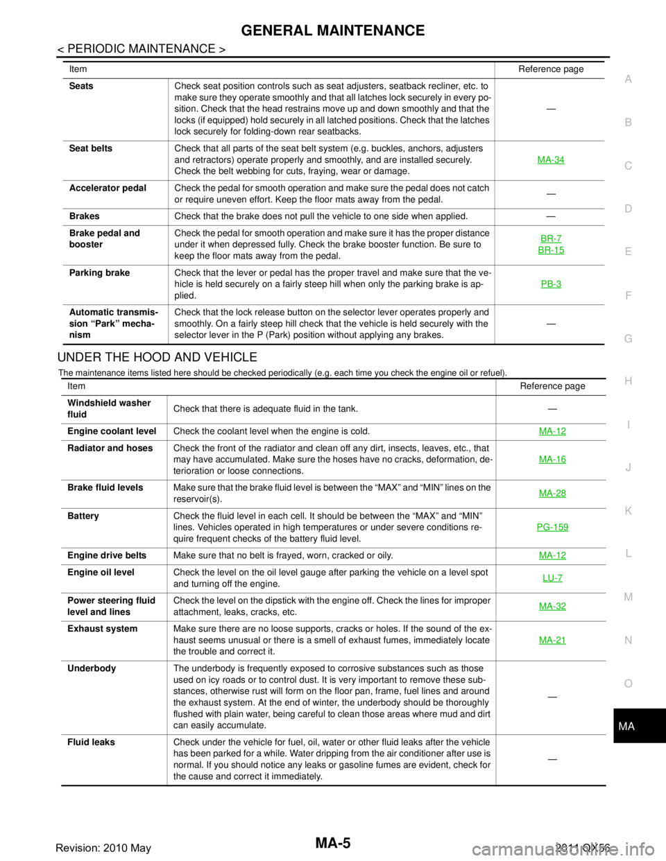
The maintenance items listed here should
be checked periodically (e.g. each time you check the engine oil or refuel).
Seats Check seat position controls such as seat adjusters, seatback recliner, etc. to
make sure they operate smoothly and that all latches lock securely in every po-
sition. Check that the head restrains move up and down smoothly and that the
locks (if equipped) hold securely in all latched positions. Check that the latches
lock securely for folding-down rear seatbacks. —
Seat belts Check that all parts of the seat belt system (e.g. buckles, anchors, adjusters
and retractors) operate properly and smoothly, and are installed securely.
Check the belt webbing for cuts, fraying, wear or damage. MA-34
Accelerator pedal
Check the pedal for smooth operation and make sure the pedal does not catch
or require uneven effort. Keep the floor mats away from the pedal. —
Brakes Check that the brake does not pull the vehicle to one side when applied. —
Brake pedal and
booster Check the pedal for smooth operation and make sure it has the proper distance
under it when depressed fully. Check the brake booster function. Be sure to
keep the floor mats away from the pedal. BR-7
BR-15
Parking brake
Check that the lever or pedal has the proper travel and make sure that the ve-
hicle is held securely on a fairly steep hill when only the parking brake is ap-
plied. PB-3
Automatic transmis-
sion “Park” mecha-
nismCheck that the lock release button on the selector lever operates properly and
smoothly. On a fairly steep hill check that the vehicle is held securely with the
selector lever in the P (Park) position without applying any brakes.
—
Item
Reference page
Item Reference page
Windshield washer
fluid Check that there is adequate fluid in the tank. —
Engine coolant level Check the coolant level when the engine is cold. MA-12
Radiator and hosesCheck the front of the radiator and clean off any dirt, insects, leaves, etc., that
may have accumulated. Make sure the hoses have no cracks, deformation, de-
terioration or loose connections. MA-16
Brake fluid levels
Make sure that the brake fluid level is between the “MAX” and “MIN” lines on the
reservoir(s). MA-28
Battery
Check the fluid level in each cell. It should be between the “MAX” and “MIN”
lines. Vehicles operated in high temperatures or under severe conditions re-
quire frequent checks of the battery fluid level. PG-159
Engine drive belts
Make sure that no belt is frayed, worn, cracked or oily. MA-12
Engine oil levelCheck the level on the oil level gauge after parking the vehicle on a level spot
and turning off the engine. LU-7
Power steering fluid
level and linesCheck the level on the dipstick with the engine off. Check the lines for improper
attachment, leaks, cracks, etc.
MA-32
Exhaust system
Make sure there are no loose supports, cracks or holes. If the sound of the ex-
haust seems unusual or there is a smell of exhaust fumes, immediately locate
the trouble and correct it. MA-21
Underbody
The underbody is frequently exposed to corrosive substances such as those
used on icy roads or to control dust. It is very important to remove these sub-
stances, otherwise rust will form on the floor pan, frame, fuel lines and around
the exhaust system. At the end of winter, the underbody should be thoroughly
flushed with plain water, being careful to clean those areas where mud and dirt
can easily accumulate. —
Fluid leaks Check under the vehicle for fuel, oil, water or other fluid leaks after the vehicle
has been parked for a while. Water dripping from the air conditioner after use is
normal. If you should notice any leaks or gasoline fumes are evident, check for
the cause and correct it immediately. —
Revision: 2010 May2011 QX56
Page 3677 of 5598

PERIODIC MAINTENANCEMA-7
< PERIODIC MAINTENANCE >
C
DE
F
G H
I
J
K L
M B
MA
N
O A
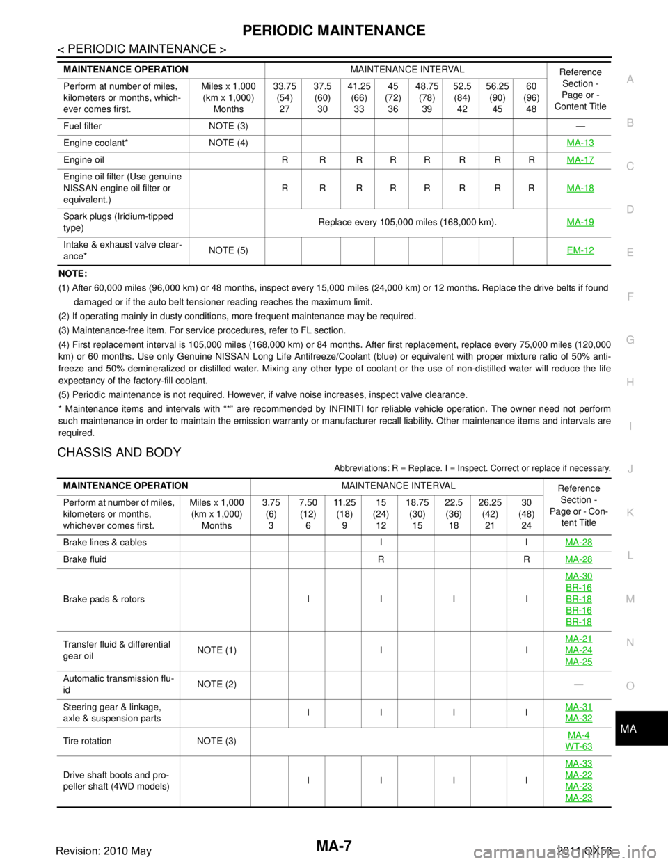
NOTE:
(1) After 60,000 miles (96,000 km) or 48 months, inspect every 15,000 miles (24,000 km) or 12 months. Replace the drive belts i
f found
damaged or if the auto belt tensioner reading reaches the maximum limit.
(2) If operating mainly in dusty conditions, more frequent maintenance may be required.
(3) Maintenance-free item. For service procedures, refer to FL section.
(4) First replacement interval is 105,000 miles (168,000 km) or 84 months. After first replacement, replace every 75,000 miles (120,000
km) or 60 months. Use only Genu ine NISSAN Long Life Antifreeze/Coo lant (blue) or equivalent with proper mixture ratio of 50% anti-
freeze and 50% demineralized or distilled water. Mixing any other type of coolant or the use of non-distilled water will reduce the life
expectancy of the factory-fill coolant.
(5) Periodic maintenance is not required. However, if valve noise increases, inspect valve clearance.
* Maintenance items and intervals with “*” are recommended by INFINITI for reliable vehicle operation. The owner need not perfo rm
such maintenance in order to maintain the emission warranty or manufacturer recall liability. Other maintenance items and inter vals are
required.
CHASSIS AND BODY
Abbreviations: R = Replace. I = Inspec t. Correct or replace if necessary.
Fuel filter NOTE (3) —
Engine coolant* NOTE (4) MA-13
Engine oil R R R R R R R RMA-17
Engine oil filter (Use genuine
NISSAN engine oil filter or
equivalent.)R R RRRRRR
MA-18
Spark plugs (Iridium-tipped
type)Replace every 105,000 miles (168,000 km).
MA-19
Intake & exhaust valve clear-
ance*NOTE (5)
EM-12
MAINTENANCE OPERATIONMAINTENANCE INTERVAL
Reference
Section -
Page or -
Content Title
Perform at number of miles,
kilometers or months, which-
ever comes first. Miles x 1,000
(km x 1,000)
Months 33.75
(54)
27 37.5
(60)
30 41.25
(66)
33 45
(72)
36 48.75
(78)
39 52.5
(84)
42 56.25
(90)
45 60
(96)
48
MAINTENANCE OPERATION MAINTENANCE INTERVAL
Reference
Section -
Page or - Con- tent Title
Perform at number of miles,
kilometers or months,
whichever comes first. Miles x 1,000
(km x 1,000)
Months 3.75
(6)
3 7.50
(12)
6 11 . 2 5
(18)
9 15
(24)
12 18.75
(30)
15 22.5
(36)
18 26.25
(42)
21 30
(48)
24
Brake lines & cables I I MA-28
Brake fluid R RMA-28
Brake pads & rotors I I I IMA-30
BR-16
BR-18
BR-16
BR-18
Transfer fluid & differential
gear oil
NOTE (1) I I MA-21MA-24
MA-25
Automatic transmission flu-
id
NOTE (2)
—
Steering gear & linkage,
axle & suspension parts IIII
MA-31
MA-32
Tire rotation NOTE (3) MA-4WT-63
Drive shaft boots and pro-
peller shaft (4WD models) IIII MA-33MA-22
MA-23
MA-23
Revision: 2010 May2011 QX56