2011 INFINITI QX56 steering
[x] Cancel search: steeringPage 3884 of 5598
![INFINITI QX56 2011 Factory Service Manual
PCS
DIAGNOSIS SYSTEM (BCM)PCS-43
< SYSTEM DESCRIPTION > [POWER DISTRIBUTION SYSTEM]
C
D
E
F
G H
I
J
K L
B A
O P
N
*: OFF is displayed when brake pedal is depressed while brake switch power supply is INFINITI QX56 2011 Factory Service Manual
PCS
DIAGNOSIS SYSTEM (BCM)PCS-43
< SYSTEM DESCRIPTION > [POWER DISTRIBUTION SYSTEM]
C
D
E
F
G H
I
J
K L
B A
O P
N
*: OFF is displayed when brake pedal is depressed while brake switch power supply is](/manual-img/42/57033/w960_57033-3883.png)
PCS
DIAGNOSIS SYSTEM (BCM)PCS-43
< SYSTEM DESCRIPTION > [POWER DISTRIBUTION SYSTEM]
C
D
E
F
G H
I
J
K L
B A
O P
N
*: OFF is displayed when brake pedal is depressed while brake switch power supply is OFF.
ACTIVE TEST
PRMT RKE STRT
NOTE:
This item is displayed, but cannot be monitored
TRNK/HAT MNTR NOTE:
This item is displayed, but cannot be monitored
RKE-LOCK Indicates [On/Off] condition of LOCK signal from Intelligent Key
RKE-UNLOCK Indicates [On/Off] condition of UNLOCK signal from Intelligent Key
RKE-TR/BD NOTE:
This item is displayed, but cannot be monitored
RKE-PANIC Indicates [On/Off] condition of PANIC button of Intelligent Key
RKE-MODE CHG Indicates [On/Off] condition of MODE CHANGE signal from Intelligent Key
RKE OPE COUN1 When remote keyless entry receiver receives the signal transmitted while operating on Intelli-
gent Key, the numerical value start changing
RKE OPE COUN2 NOTE:
This item is displayed, but cannot be monitored
Monitor Item Condition
Test item Description
BATTERY SAVER This test is able to check interior room lamp operation
On: Operate
Off: Non-operation
OUTSIDE BUZZER This test is able to check Intelligent Key warning buzzer operation
On: Operate
Off: Non-operation
INSIDE BUZZER This test is able to check warning chime in combination meter operation
Take Out: Take away warning chime sounds when CONSULT-III screen is touched
Key: Key warning chime sounds when CONSULT-III screen is touched
Knob: OFF position warning chime sounds when CONSULT-III screen is touched
Off: Non-operation
INDICATOR This test is able to check warning lamp operation
KEY ON: “KEY” Warning lamp illuminates when CONSULT-III screen is touched
KEY IND: “KEY” Warning lamp blinks when CONSULT-III screen is touched
Off: Non-operation
INT LAMP This test is able to check interior room lamp operation
On: Operate
Off: Non-operation
LCD This test is able to check meter display information
Engine start information displays when “BP N” on CONSULT-III screen is touched
Engine start information displays when “BP I” on CONSULT-III screen is touched
Key ID warning displays when “ID NG” on CONSULT-III screen is touched
Steering lock information displays when “ROTAT” on CONSULT-III screen is touched
P position warning displays when “SFT P” on CONSULT-III screen is touched
INSRT: This item is displayed, but cannot be monitored
BATT: This item is displayed, but cannot be monitored
Take away through window warning displays when “NO KY” on CONSULT-III screen is
touched
Take away warning displa y when “OUTKEY” on CONSUL T-III screen is touched
OFF position warning display when “LK WN” on CONSULT-III screen is touched
FLASHER This test is able to check security hazard lamp operation
The hazard lamps are activated after “LH/RH/Off” on CONSULT-III screen is touched
P RANGE This test is able to check A/T shift selector power supply
On: Operate
Off: Non-operation
ENGINE SW ILLUMI This test is able to check push-button ignition switch illumination operation
Push-ignition switch illumination illuminates when “ON” on CONSULT-III screen is touched
Revision: 2010 May2011 QX56
Page 4086 of 5598
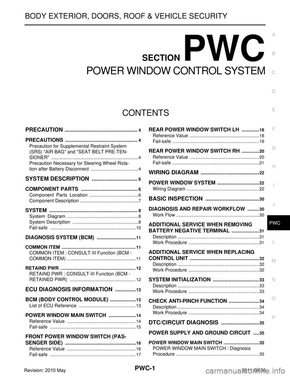
PWC-1
BODY EXTERIOR, DOORS, ROOF & VEHICLE SECURITY
C
D
E
F
G H
I
J
L
M
SECTION PWC
A
B
PWC
N
O P
CONTENTS
POWER WINDOW CONTROL SYSTEM
PRECAUTION ................ ...............................4
PRECAUTIONS .............................................. .....4
Precaution for Supplemental Restraint System
(SRS) "AIR BAG" and "SEAT BELT PRE-TEN-
SIONER" ............................................................. ......
4
Precaution Necessary for Steering Wheel Rota-
tion after Battery Disconnect .....................................
4
SYSTEM DESCRIPTION ..............................6
COMPONENT PARTS ................................... .....6
Component Parts Location ................................ ......6
Component Description .............................................7
SYSTEM ..............................................................8
System Diagram ................................................. ......8
System Description ...................................................8
Fail-safe ..................................................................10
DIAGNOSIS SYSTEM (BCM) ............................11
COMMON ITEM ..................................................... ....11
COMMON ITEM : CONSULT-III Function (BCM -
COMMON ITEM) .....................................................
11
RETAIND PWR ...................................................... ....12
RETAIND PWR : CONSULT-III Function (BCM -
RETAINED PWR) ...................................................
12
ECU DIAGNOSIS INFORMATION ..............13
BCM (BODY CONTROL MODULE) ............... ....13
List of ECU Reference ........................................ ....13
POWER WINDOW MAIN SWITCH ....................14
Reference Value ................................................. ....14
Fail-safe ..................................................................15
FRONT POWER WINDOW SWITCH (PAS-
SENGER SIDE) ..................................................
16
Reference Value ................................................. ....16
Fail-safe ..................................................................17
REAR POWER WINDOW SWITCH LH ............18
Reference Value .................................................. ....18
Fail-safe ...................................................................19
REAR POWER WINDOW SWITCH RH ............20
Reference Value ......................................................20
Fail-safe ...................................................................21
WIRING DIAGRAM ......................................22
POWER WINDOW SYSTEM .............................22
Wiring Diagram .................................................... ....22
BASIC INSPECTION ...................................30
DIAGNOSIS AND REPAIR WORKFLOW ........30
Work Flow ............................................................ ....30
ADDITIONAL SERVICE WHEN REMOVING
BATTERY NEGATIVE TERMINAL ...................
31
Description ...............................................................31
Work Procedure .......................................................31
ADDITIONAL SERVICE WHEN REPLACING
CONTROL UNIT ................................................
32
Description ...............................................................32
Work Procedure .......................................................32
SYSTEM INITIALIZATION ................................33
Description ........................................................... ....33
Work Procedure .......................................................33
CHECK ANTI-PINCH FUNCTION .....................34
Description ...............................................................34
Work Procedure .......................................................34
DTC/CIRCUIT DIAGNOSIS .........................35
POWER SUPPLY AND GROUND CIRCUIT ....35
POWER WINDOW MAIN SWITCH ........................ ....35
POWER WINDOW MAIN SWITCH : Diagnosis
Procedure ................................................................
35
Revision: 2010 May2011 QX56
Page 4089 of 5598
PWC-4
< PRECAUTION >
PRECAUTIONS
PRECAUTION
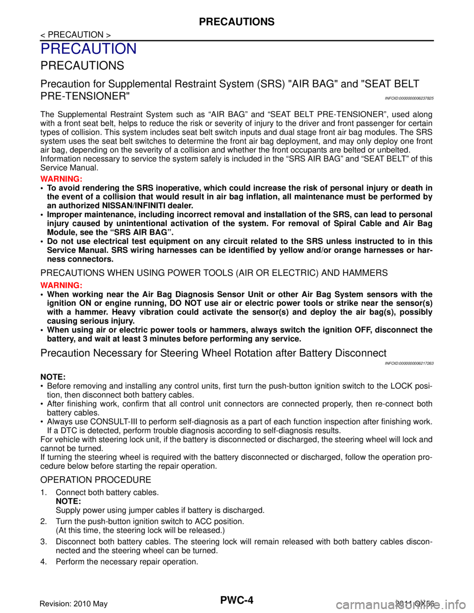
PRECAUTIONS
Precaution for Supplemental Restraint System (SRS) "AIR BAG" and "SEAT BELT
PRE-TENSIONER"
INFOID:0000000006237825
The Supplemental Restraint System such as “A IR BAG” and “SEAT BELT PRE-TENSIONER”, used along
with a front seat belt, helps to reduce the risk or severi ty of injury to the driver and front passenger for certain
types of collision. This system includes seat belt switch inputs and dual stage front air bag modules. The SRS
system uses the seat belt switches to determine the front air bag deployment, and may only deploy one front
air bag, depending on the severity of a collision and w hether the front occupants are belted or unbelted.
Information necessary to service the system safely is included in the “SRS AIR BAG” and “SEAT BELT” of this
Service Manual.
WARNING:
• To avoid rendering the SRS inopera tive, which could increase the risk of personal injury or death in
the event of a collision that would result in air bag inflation, all maintenance must be performed by
an authorized NISS AN/INFINITI dealer.
Improper maintenance, including in correct removal and installation of the SRS, can lead to personal
injury caused by unintent ional activation of the system. For re moval of Spiral Cable and Air Bag
Module, see the “SRS AIR BAG”.
Do not use electrical test equipmen t on any circuit related to the SRS unless instructed to in this
Service Manual. SRS wiring harnesses can be identi fied by yellow and/or orange harnesses or har-
ness connectors.
PRECAUTIONS WHEN USING POWER TOOLS (AIR OR ELECTRIC) AND HAMMERS
WARNING:
When working near the Air Bag Diagnosis Sensor Unit or other Air Bag System sensors with the ignition ON or engine running, DO NOT use air or electric power tools or strike near the sensor(s)
with a hammer. Heavy vibration could activate the sensor(s) and deploy the air bag(s), possibly
causing serious injury.
When using air or electric power tools or hammers , always switch the ignition OFF, disconnect the
battery, and wait at least 3 minu tes before performing any service.
Precaution Necessary for Steering W heel Rotation after Battery Disconnect
INFOID:0000000006217263
NOTE:
Before removing and installing any control units, first tu rn the push-button ignition switch to the LOCK posi-
tion, then disconnect bot h battery cables.
After finishing work, confirm that all control unit connectors are connected properly, then re-connect both
battery cables.
Always use CONSULT-III to perform self-diagnosis as a part of each function inspection after finishing work.
If a DTC is detected, perform trouble diagnos is according to self-diagnosis results.
For vehicle with steering lock unit, if the battery is disconnected or discharged, the steering wheel will lock and
cannot be turned.
If turning the steering wheel is required with the bat tery disconnected or discharged, follow the operation pro-
cedure below before starting the repair operation.
OPERATION PROCEDURE
1. Connect both battery cables. NOTE:
Supply power using jumper cables if battery is discharged.
2. Turn the push-button ignition switch to ACC position. (At this time, the steering lock will be released.)
3. Disconnect both battery cables. The steering lock wi ll remain released with both battery cables discon-
nected and the steering wheel can be turned.
4. Perform the necessary repair operation.
Revision: 2010 May2011 QX56
Page 4090 of 5598
PRECAUTIONSPWC-5
< PRECAUTION >
C
DE
F
G H
I
J
L
M A
B
PWC
N
O P
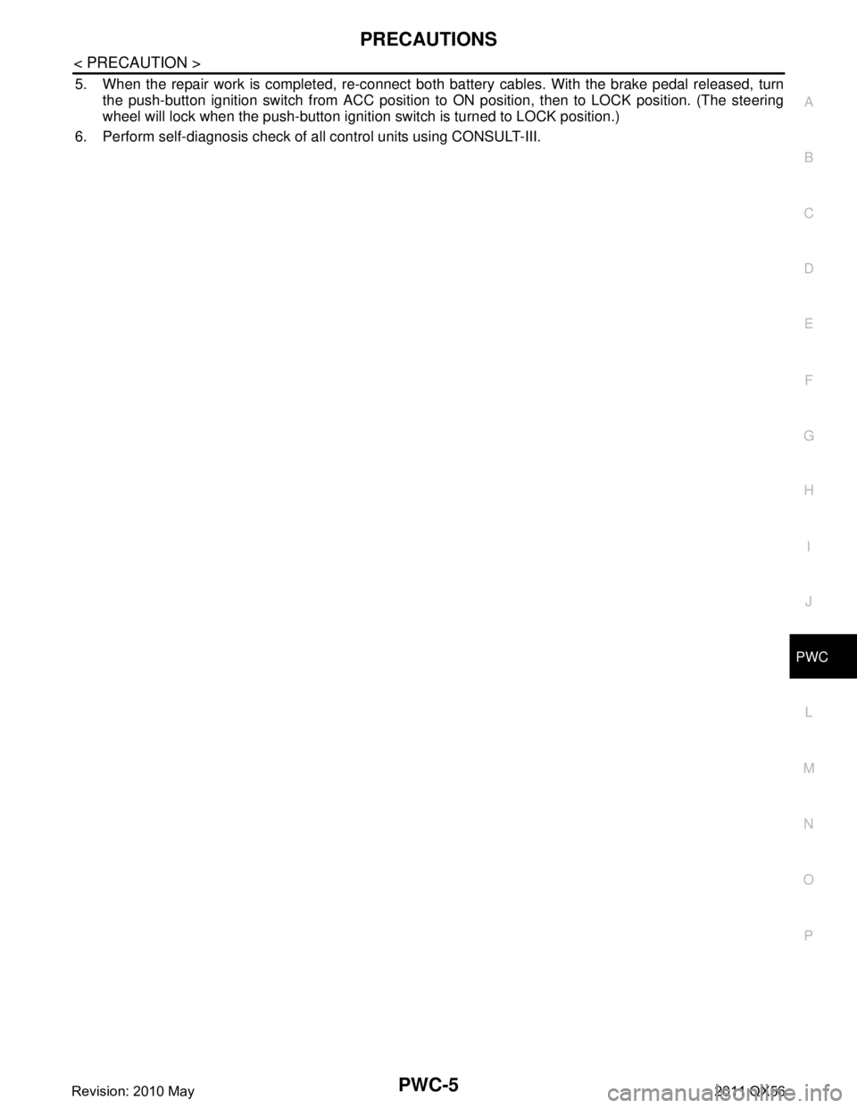
5. When the repair work is completed, re-connect both battery cables. With the brake pedal released, turn
the push-button ignition switch from ACC position to ON position, then to LOCK position. (The steering
wheel will lock when the push-button ignition switch is turned to LOCK position.)
6. Perform self-diagnosis check of a ll control units using CONSULT-III.
Revision: 2010 May2011 QX56
Page 4097 of 5598

PWC-12
< SYSTEM DESCRIPTION >
DIAGNOSIS SYSTEM (BCM)
RETAIND PWR
RETAIND PWR : CONSULT-III Function (BCM - RETAINED PWR)INFOID:0000000006217270
Data monitor
CONSULT screen item Indication/Unit Description
Vehicle Speed km/h Vehicle speed of the moment a particular DTC is detected
Odo/Trip Meter km Total mileage (Odometer value) of the moment a particular DTC is detected
Vehicle Condition SLEEP>LOCK
Power position status of
the moment a particular
DTC is detected While turning BCM status from low power consumption mode to
normal mode (Power supply position is “LOCK”)
SLEEP>OFF While turning BCM status from low power consumption mode to
normal mode (Power supply position is “OFF”.)
LOCK>ACC While turning power supply position from “LOCK” to “ACC”
ACC>ON While turning power supply position from “ACC” to “IGN”
RUN>ACC While turning power supp
ly position from “RUN” to “ACC” (Vehicle
is stopping and selector lever is except P position.)
CRANK>RUN While turning power su
pply position from “CRANKING” to “RUN”
(From cranking up the engine to run it)
RUN>URGENT While turning power supply positi
on from “RUN“ to “ACC” (Emer-
gency stop operation)
ACC>OFF While turning power supply position from “ACC” to “OFF”
OFF>LOCK While turning power supply position from “OFF” to “LOCK”
OFF>ACC While turning power supply position from “OFF” to “ACC”
ON>CRANK While turning power supply position from “IGN” to “CRANKING”
OFF>SLEEP While turning BCM status from normal mode (Power supply posi-
tion is “OFF”.) to low power consumption mode
LOCK>SLEEP While turning BCM status from normal mode (Power supply posi-
tion is “LOCK”.) to low power consumption mode
LOCK Power supply position is “LOCK”
(Ignition switch OFF with steer-
ing is locked.)
OFF Power supply position is “OFF” (Ignition switch OFF with steering
is unlocked.)
ACC Power supply position is “ACC” (Ignition switch ACC)
ON Power supply position is “IGN” (Ignition switch ON with engine
stopped)
ENGINE RUN Power supply position is “RUN” (Ignition switch ON with engine
running)
CRANKING Power supply position is “CRANKING” (At engine cranking)
IGN Counter 0 - 39 The number of times that ignition switch is turned ON after DTC is detected
The number is 0 when a malfunction is detected now.
The number increases like 1
→ 2 → 3...38 → 39 after returning to the normal condition
whenever ignition switch OFF → ON.
The number is fixed to 39 until the self-diagnosis results are erased if it is over 39.
Monitor Item Description
DOOR SW-DR Indicates [ON/OFF] condition of driver side door switch.
DOOR SW-AS Indicates [ON/OFF] condition of passenger side door switch.
Revision: 2010 May2011 QX56
Page 4200 of 5598
RAX-4
< SYMPTOM DIAGNOSIS >
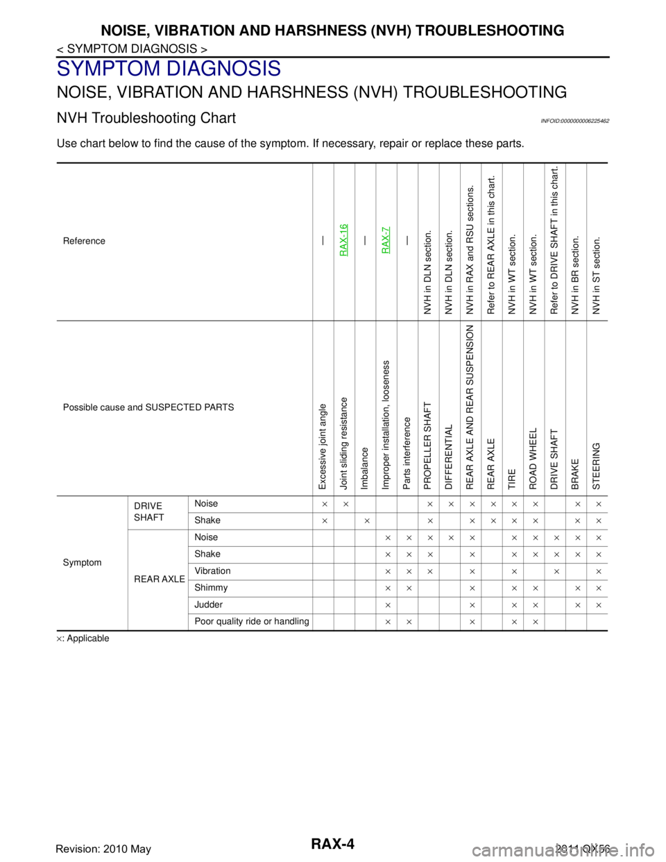
NOISE, VIBRATION AND HARSHNESS (NVH) TROUBLESHOOTING
SYMPTOM DIAGNOSIS
NOISE, VIBRATION AND HARSHNESS (NVH) TROUBLESHOOTING
NVH Troubleshooting ChartINFOID:0000000006225462
Use chart below to find the cause of the symptom. If necessary, repair or replace these parts.
×: ApplicableReference
—
RAX-16—
RAX-7—
NVH in DLN section.
NVH in DLN section.
NVH in RAX and RSU sections.
Refer to REAR AXLE in this chart.
NVH in WT section.
NVH in WT section.
Refer to DRIVE SHAFT in this chart.
NVH in BR section.
NVH in ST section.
Possible cause and SUSPECTED PARTS
Excessive joint angle
Joint sliding resistance
Imbalance
Improper installation, looseness
Parts interference
PROPELLER SHAFT
DIFFERENTIAL
REAR AXLE AND REAR SUSPENSION
REAR AXLE
TIRE
ROAD WHEEL
DRIVE SHAFT
BRAKE
STEERING
Symptom DRIVE
SHAFT
Noise
×× ×××××× ××
Shake ×× ×××××××
REAR AXLE Noise
××××× ×××××
Shake ××× × ×××××
Vibration ×××××××
Shimmy ×× × ×× ××
Judder × × ×× ××
Poor quality ride or handling ×× × ××
Revision: 2010 May2011 QX56
Page 4205 of 5598
REAR WHEEL HUB AND HOUSINGRAX-9
< REMOVAL AND INSTALLATION >
CEF
G H
I
J
K L
M A
B
RAX
N
O P
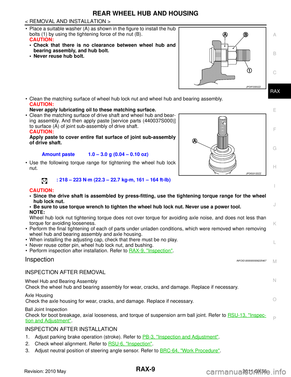
Place a suitable washer (A) as shown in the figure to install the hub bolts (1) by using the tightening force of the nut (B).
CAUTION:
Check that there is no cl earance between wheel hub and
bearing assembly, and hub bolt.
Never reuse hub bolt.
Clean the matching surface of wheel hub lock nut and wheel hub and bearing assembly. CAUTION:
Never apply lubricating oi l to these matching surface.
Clean the matching surface of drive shaft and wheel hub and bear-
ing assembly. And then apply paste [service parts (440037S000)]
to surface (A) of joint sub-assembly of drive shaft.
CAUTION:
Apply paste to cover entire fl at surface of joint sub-assembly
of drive shaft.
Use the following torque range for tightening the wheel hub lock nut.
CAUTION:
Since the drive shaft is assembled by press-fitting , use the tightening torque range for the wheel
hub lock nut.
Be sure to use torque wrench to tighten th e wheel hub lock nut. Never use a power tool.
NOTE:
Wheel hub lock nut tightening torque does not over tor que for avoiding axle noise, and does not less than
torque for avoiding looseness.
Perform the final tightening of each of parts under unladen conditions, which were removed when removing wheel hub and bearing assembly and axle housing.
When installing the adjusting cap, check that there must be no play.
Never reuse cotter pin, wheel hub lock nut, and bushing.
Perform inspection after installation. Refer to RAX-9, "
Inspection".
InspectionINFOID:0000000006225467
INSPECTION AFTER REMOVAL
Wheel Hub and Bearing Assembly
Check the wheel hub and bearing assembly for wear, cracks, and damage. Replace if necessary.
Axle Housing
Check the axle housing for wear, cracks, and damage. Replace if necessary.
Ball Joint Inspection
Check for boot breakage, axial looseness, and torque of suspension arm ball joint. Refer to RSU-13, "Inspec-
tion and Adjustment".
INSPECTION AFTER INSTALLATION
1. Adjust parking brake operation (stroke). Refer to PB-3, "Inspection and Adjustment".
2. Check wheel alignment. Refer to RSU-6, "
Inspection".
3. Adjust neutral position of steering angle sensor. Refer to BRC-64, "
Work Procedure".
JPDIF0300ZZ
Amount paste 1.0 – 3.0 g (0.04 – 0.10 oz)
: 218 – 223 N·m (22.3 – 22.7 kg-m, 161 – 164 ft-lb)
JPDIG0122ZZ
Revision: 2010 May2011 QX56
Page 4213 of 5598
REAR DRIVE SHAFTRAX-17
< REMOVAL AND INSTALLATION >
CEF
G H
I
J
K L
M A
B
RAX
N
O P
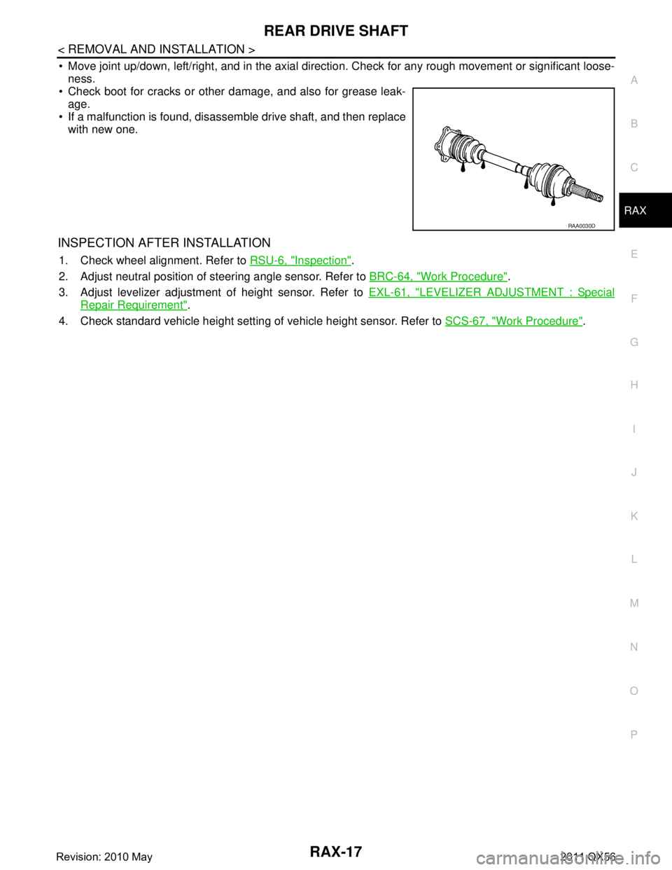
Move joint up/down, left/right, and in the axial directi on. Check for any rough movement or significant loose-
ness.
Check boot for cracks or other damage, and also for grease leak-
age.
If a malfunction is found, disassem ble drive shaft, and then replace
with new one.
INSPECTION AFTER INSTALLATION
1. Check wheel alignment. Refer to RSU-6, "Inspection".
2. Adjust neutral position of steering angle sensor. Refer to BRC-64, "
Work Procedure".
3. Adjust levelizer adjustment of height sensor. Refer to EXL-61, "
LEVELIZER ADJUSTMENT : Special
Repair Requirement".
4. Check standard vehicle height setting of vehicle height sensor. Refer to SCS-67, "
Work Procedure".
RAA0030D
Revision: 2010 May2011 QX56