2011 INFINITI QX56 engine
[x] Cancel search: enginePage 1577 of 5598

DIAGNOSIS SYSTEM (BCM)DLK-41
< SYSTEM DESCRIPTION >
C
DE
F
G H
I
J
L
M A
B
DLK
N
O P
INTELLIGENT KEY : CONSULT-III Fu nction (BCM - INTELLIGENT KEY)INFOID:0000000006225856
WORK SUPPORT
Monitor item Description
INSIDE ANT DIAGNOSIS This function allows inside key antenna self-diagnosis
LOCK/UNLOCK BY I-KEY Door lock/unlock function by door request switch mode can be changed to operation in this
mode
On: Operate
Off: Non-operation
ENGINE START BY I-KEY Engine start function mode can be changed to operation with this mode
On: Operate
Off: Non-operation
TRUNK/GLASS HATCH OPEN Buzzer reminder function mode by back door opener switch can be changed to operation with
this mode
On: Operate
Off: Non-operation
PANIC ALARM SET Panic alarm button pressing time on Intelligent Key button can be selected from the following
with this mode
MODE 1: 0.5 sec
MODE 2: Non-operation
MODE 3: 1.5 sec
TRUNK OPEN DELAY Back door open button pressing to Intelligent Key button can be selected as per the following
in this mode
MODE 1: Press and hold
MODE 2: Press twice
MODE 3: Press and hold, or press twice
LO- BATT OF KEY FOB WARN Intelligent Key low battery warning mode can be changed to operation with this mode
On: Operate
Off: Non-operation
ANTI KEY LOCK IN FUNCTI Key reminder function mode can be changed to operation with this mode
On: Operate
Off: Non-operation
HAZARD ANSWER BACK Hazard reminder function mode by door request switch and Intelligent Key button can be se-
lected from the following with this mode
Lock Only: Door lock operation only
Unlock Only: Door unlock operation only
Lock/Unlock: Lock and unlock operation
Off: Non-operation
ANS BACK I-KEY LOCK Buzzer reminder function (lock operation) mode by door request switch can be selected from
the following with this mode
Horn Chirp: Sound horn
Buzzer: Sound Intelligent Key warning buzzer
Off: Non-operation
ANS BACK I-KEY UNLOCK Buzzer reminder function (unlock operation) mode by door request switch can be changed to
operation with this mode
On: Operate
Off: Non-operation
SHORT CRANKING OUTPUT Starter motor can operate during the times below
70 msec
100 msec
200 msec
CONFIRM KEY FOB ID It can be checked wh ether Intelligent Key ID code is registered or not in this mode
Revision: 2010 May2011 QX56
Page 1578 of 5598

DLK-42
< SYSTEM DESCRIPTION >
DIAGNOSIS SYSTEM (BCM)
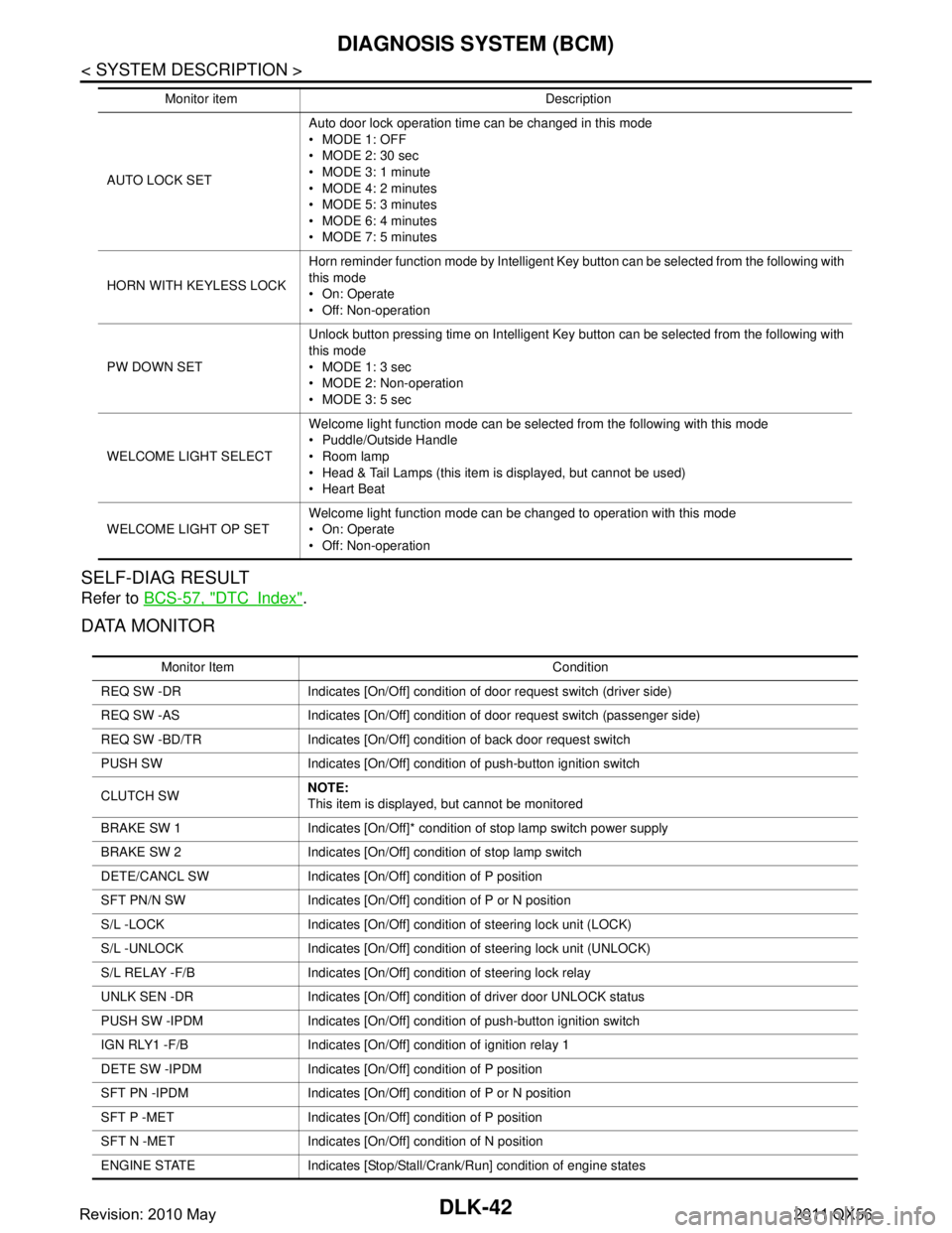
SELF-DIAG RESULT
Refer to BCS-57, "DTCIndex".
DATA MONITOR
AUTO LOCK SET Auto door lock operation time can be changed in this mode
MODE 1: OFF
MODE 2: 30 sec
MODE 3: 1 minute
MODE 4: 2 minutes
MODE 5: 3 minutes
MODE 6: 4 minutes
MODE 7: 5 minutes
HORN WITH KEYLESS LOCK Horn reminder function mode by Intelligent Key button can be selected from the following with
this mode
On: Operate
Off: Non-operation
PW DOWN SET Unlock button pressing time on Intelligent Key button can be selected from the following with
this mode
MODE 1: 3 sec
MODE 2: Non-operation
MODE 3: 5 sec
WELCOME LIGHT SELECT Welcome light function mode can be selected from the following with this mode
Puddle/Outside Handle
Room lamp
Head & Tail Lamps (this item is displayed, but cannot be used)
Heart Beat
WELCOME LIGHT OP SET Welcome light function mode can be changed to operation with this mode
On: Operate
Off: Non-operation
Monitor item Description
Monitor Item Condition
REQ SW -DR Indicates [On/Off] condition of door request switch (driver side)
REQ SW -AS Indicates [On/Off] condition of door request switch (passenger side)
REQ SW -BD/TR Indicates [On/Off] condition of back door request switch
PUSH SW Indicates [On/Off] condition of push-button ignition switch
CLUTCH SW NOTE:
This item is displayed, but cannot be monitored
BRAKE SW 1 Indicates [On/Off]* condition of stop lamp switch power supply
BRAKE SW 2 Indicates [On/Off] condition of stop lamp switch
DETE/CANCL SW Indicates [On/Off] condition of P position
SFT PN/N SW Indicates [On/Off] condition of P or N position
S/L -LOCK Indicates [On/Off] condition of steering lock unit (LOCK)
S/L -UNLOCK Indicates [On/Off] condition of steering lock unit (UNLOCK)
S/L RELAY -F/B Indicates [On/Off] condition of steering lock relay
UNLK SEN -DR Indicates [On/Off] condition of driver door UNLOCK status
PUSH SW -IPDM Indicates [On/Off] condition of push-button ignition switch
IGN RLY1 -F/B Indicates [On/Off] condition of ignition relay 1
DETE SW -IPDM Indicates [On/Off] condition of P position
SFT PN -IPDM Indicates [On/Off] condition of P or N position
SFT P -MET Indicates [On/Off] condition of P position
SFT N -MET Indicates [On/Off] condition of N position
ENGINE STATE Indicates [Stop/Stall/Crank/Run] condition of engine states
Revision: 2010 May2011 QX56
Page 1579 of 5598

DIAGNOSIS SYSTEM (BCM)DLK-43
< SYSTEM DESCRIPTION >
C
DE
F
G H
I
J
L
M A
B
DLK
N
O P
*: OFF is displayed when brake pedal is depressed while brake switch power supply is OFF.
ACTIVE TEST
S/L LOCK-IPDM Indicates [On/Off] condition of steering lock unit (LOCK)
S/L UNLK-IPDM Indicates [On/Off] condition of steering lock unit (UNLOCK)
S/L RELAY-REQ Indicates [On/Off] condition of steering lock relay
VEH SPEED 1 Display the vehicle speed signal received from combination meter by numerical value [Km/h]
VEH SPEED 2 Display the vehicle spee d signal received from ABS or VDC or TCM by numerical value [Km/h]
DOOR STAT-DR Indicates [LOCK/READY/UNLK] condition of unlock sensor
DOOR STAT-AS Indicates [LOCK/READY/UNLK] condition of passenger side door status
ID OK FLAG Indicates [Set/Reset] condition of key ID
PRMT ENG STRT Indicates [Set/Reset] condition of engine start possibility
PRMT RKE STRT NOTE:
This item is displayed, but cannot be monitored
TRNK/HAT MNTR NOTE:
This item is displayed, but cannot be monitored
RKE-LOCK Indicates [On/Off] condition of LOCK signal from Intelligent Key
RKE-UNLOCK Indicates [On/Off] condition of UNLOCK signal from Intelligent Key
RKE-TR/BD NOTE:
This item is displayed, but cannot be monitored
RKE-PANIC Indicates [On/Off] condition of PANIC button of Intelligent Key
RKE-MODE CHG Indicates [On/Off] condition of MODE CHANGE signal from Intelligent Key
RKE OPE COUN1 When remote keyless entry receiver receives the signal transmitted while operating on Intelli-
gent Key, the numerical value start changing
RKE OPE COUN2 NOTE:
This item is displayed, but cannot be monitored
Monitor Item Condition
Test item Description
BATTERY SAVER This test is able to check interior room lamp operation
On: Operate
Off: Non-operation
OUTSIDE BUZZER This test is able to check Intelligent Key warning buzzer operation
On: Operate
Off: Non-operation
INSIDE BUZZER This test is able to check warning chime in combination meter operation
Take Out: Take away warning chime sounds when CONSULT-III screen is touched
Key: Key warning chime sounds when CONSULT-III screen is touched
Knob: OFF position warning chime sounds when CONSULT-III screen is touched
Off: Non-operation
INDICATOR This test is able to check warning lamp operation
KEY ON: “KEY” Warning lamp illuminates when CONSULT-III screen is touched
KEY IND: “KEY” Warning lamp blinks when CONSULT-III screen is touched
Off: Non-operation
INT LAMP This test is able to check interior room lamp operation
On: Operate
Off: Non-operation
Revision: 2010 May2011 QX56
Page 1580 of 5598

DLK-44
< SYSTEM DESCRIPTION >
DIAGNOSIS SYSTEM (BCM)
TRUNK
TRUNK : CONSULT-III Function (BCM - TRUNK)INFOID:0000000006225857
DATA MONITOR
LCD This test is able to check meter display information
Engine start information displays when “BP N” on CONSULT-III screen is touched
Engine start information displays when “BP I” on CONSULT-III screen is touched
Key ID warning displays when “ID NG” on CONSULT-III screen is touched
Steering lock information displays when “ROTAT” on CONSULT-III screen is touched
P position warning displays when “SFT P” on CONSULT-III screen is touched
INSRT: This item is displayed, but cannot be monitored
BATT: This item is displayed, but cannot be monitored
Take away through window warning displays
when “NO KY” on CONSULT-III screen is
touched
Take away warning display when “OUTKEY” on CONSULT-III screen is touched
OFF position warning display when “LK WN” on CONSULT-III screen is touched
FLASHER This test is able to check security hazard lamp operation
The hazard lamps are activated after “LH/RH/Off” on CONSULT-III screen is touched
P RANGE This test is able to check A/T shift selector power supply
On: Operate
Off: Non-operation
ENGINE SW ILLUMI This test is able to check push-button ignition switch illumination operation
Push-ignition switch illumination illuminates when “ON” on CONSULT-III screen is touched
LOCK INDICATOR This test is able to check LOCK indicato
r (push-button ignition switch) operation
On: Operate
Off: Non-operation
ACC INDICATOR This test is able to check ACC indicator (push-button ignition switch) operation
On: Operate
Off: Non-operation
IGNITION ON IND This test is able to check ON indicator (push-button ignition switch) operation
On: Operate
Off: Non-operation
HORN This test is able to check horn operation
On: Operate
Off: Non-operation
TRUNK/BACK DOOR NOTE:
This item is displayed, but cannot be used
Test item Description
Monitor Item Contents
PUSH SW Indicates [On/Off] condition of push switch
UNLK SEN -DR Indicates [On/Off] condition of unlock sensor
VEH SPEED 1 Indicates [Km/h] condition of ve hicle speed signal from combination meter
TR/BD OPEN SW Indicates [On/Off] condition of back door opener switch
TRNK/HAT MNTR NOTE:
This item is displayed, but cannot be monitored
RKE-TR/BD NOTE:
This item is displayed, but cannot be monitored
Revision: 2010 May2011 QX56
Page 1746 of 5598

DLK-210
< SYMPTOM DIAGNOSIS >
SQUEAK AND RATTLE TROUBLE DIAGNOSES
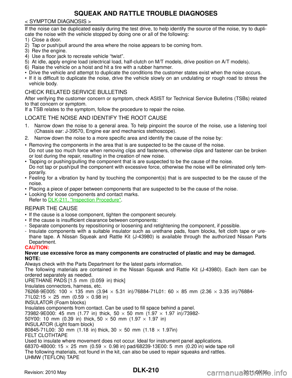
If the noise can be duplicated easily during the test drive, to help identify the source of the noise, try to dupli-
cate the noise with the vehicle stopped by doing one or all of the following:
1) Close a door.
2) Tap or push/pull around the area where the noise appears to be coming from.
3) Rev the engine.
4) Use a floor jack to recreate vehicle “twist”.
5) At idle, apply engine load (electrical load, half-cl utch on M/T models, drive position on A/T models).
6) Raise the vehicle on a hoist and hit a tire with a rubber hammer.
Drive the vehicle and attempt to duplicate the conditions the customer states exist when the noise occurs.
If it is difficult to duplicate the noise, drive the v ehicle slowly on an undulating or rough road to stress the
vehicle body.
CHECK RELATED SERVICE BULLETINS
After verifying the customer concern or symptom, chec k ASIST for Technical Service Bulletins (TSBs) related
to that concern or symptom.
If a TSB relates to the symptom, follo w the procedure to repair the noise.
LOCATE THE NOISE AND IDENTIFY THE ROOT CAUSE
1. Narrow down the noise to a general area. To help pi npoint the source of the noise, use a listening tool
(Chassis ear: J-39570, Engine ear and mechanics stethoscope).
2. Narrow down the noise to a more specific area and identify the cause of the noise by:
Removing the components in the area that is are suspected to be the cause of the noise.
Do not use too much force when removing clips and fasteners, otherwise clips and fastener can be broken
or lost during the repair, resulting in the creation of new noise.
Tapping or pushing/pulling the component that is are suspected to be the cause of the noise.
Do not tap or push/pull the component with excessive force, otherwise the noise will be eliminated only tem-
porarily.
Feeling for a vibration by hand by touching the component (s) that is are suspected to be the cause of the
noise.
Placing a piece of paper between components that are suspected to be the cause of the noise.
Looking for loose components and contact marks. Refer to DLK-211, "
Inspection Procedure".
REPAIR THE CAUSE
If the cause is a loose component, tighten the component securely.
If the cause is insufficient clearance between components:
- Separate components by repositioning or loos ening and retightening the component, if possible.
- Insulate components with a suitable insulator such as urethane pads, foam blocks, felt cloth tape or ure-
thane tape. A Nissan Squeak and Rattle Kit (J-43980) is available through the authorized Nissan Parts
Department.
CAUTION:
Never use excessive force as many components are constructed of plastic and may be damaged.
NOTE:
Always check with the Parts Departm ent for the latest parts information.
The following materials are contained in the Nissan Squeak and Rattle Kit (J-43980). Each item can be
ordered separately as needed.
URETHANE PADS [1.5 mm (0.059 in) thick]
Insulates connectors, harness, etc.
76268-9E005: 100 ×135 mm (3.94 ×5.31 in)/76884-71L01: 60 ×85 mm (2.36 ×3.35 in)/76884-
71L02:15 ×25 mm (0.59 ×0.98 in)
INSULATOR (Foam blocks)
Insulates components from contact. Can be used to fill space behind a panel.
73982-9E000: 45 mm (1.77 in) thick, 50 ×50 mm (1.97 ×1.97 in)/73982-
50Y00: 10 mm (0.39 in) thick, 50 ×50 mm (1.97 ×1.97 in)
INSULATOR (Light foam block)
80845-71L00: 30 mm (1.18 in) thick, 30 ×50 mm (1.18 ×1.97in)
FELT CLOTHTAPE
Used to insulate where movement does not occu r. Ideal for instrument panel applications.
68370-4B000: 15 ×25 mm (0.59 ×0.98 in) pad/68239-13E00: 5 mm (0.20 in) wide tape roll
The following materials, not found in the kit, can also be used to repair squeaks and rattles.
UHMW (TEFLON) TAPE
Revision: 2010 May2011 QX56
Page 1748 of 5598

DLK-212
< SYMPTOM DIAGNOSIS >
SQUEAK AND RATTLE TROUBLE DIAGNOSES
Most of these incidents can be repaired by adjusting, securing or insulating the item(s) or component(s) caus-
ing the noise.
SUNROOF/HEADLINING
Noises in the sunroof/headlining area c an often be traced to one of the following:
1. Sunroof lid, rail, linkage or seals making a rattle or light knocking noise
2. Sunvisor shaft shaking in the holder
3. Front or rear windshield touching headlining and squeaking
Again, pressing on the components to stop the noise while duplicating the conditions can isolate most of these
incidents. Repairs usually consist of insulating with felt cloth tape.
SEATS
When isolating seat noise it is important to note t he position the seat is in and the load placed on the seat
when the noise is present. These conditions should be duplicated when verifying and isolating the cause of
the noise.
Cause of seat noise include:
1. Headrest rods and holder
2. A squeak between the seat pad cushion and frame
3. Rear seatback lock and bracket
These noises can be isolated by moving or pressing on the suspected components while duplicating the con-
ditions under which the noise occurs. Most of thes e incidents can be repaired by repositioning the component
or applying urethane tape to the contact area.
UNDERHOOD
Some interior noise may be caused by components under the hood or on the engine wall. The noise is then
transmitted into the passenger compartment.
Causes of transmitted underhood noise include:
1. Any component mounted to the engine wall
2. Components that pass through the engine wall
3. Engine wall mounts and connectors
4. Loose radiator mounting pins
5. Hood bumpers out of adjustment
6. Hood striker out of adjustment
These noises can be difficult to isolate since they cannot be reached from the interior of the vehicle. The best
method is to secure, move or insulate one component at a time and test drive the \
vehicle. Also, engine RPM
or load can be changed to isolate the noise. Repairs can usually be made by moving, adjusting, securing, or
insulating the component causing the noise.
Revision: 2010 May2011 QX56
Page 1788 of 5598

DLK-252
< REMOVAL AND INSTALLATION >
CAB MOUNTING INSULATOR
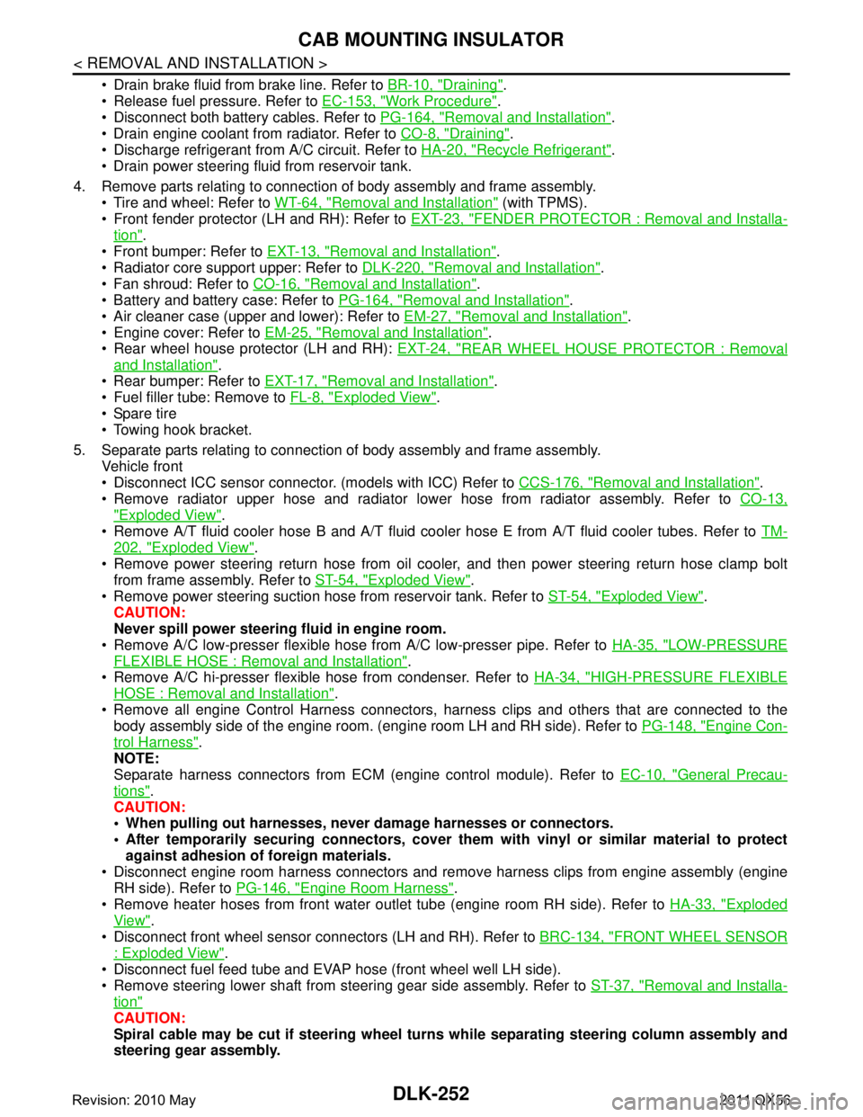
Drain brake fluid from brake line. Refer to BR-10, "Draining".
Release fuel pressure. Refer to EC-153, "
Work Procedure".
Disconnect both battery cables. Refer to PG-164, "
Removal and Installation".
Drain engine coolant from radiator. Refer to CO-8, "
Draining".
Discharge refrigerant from A/C circuit. Refer to HA-20, "
Recycle Refrigerant".
Drain power steering fluid from reservoir tank.
4. Remove parts relating to connection of body assembly and frame assembly. Tire and wheel: Refer to WT-64, "
Removal and Installation" (with TPMS).
Front fender protector (LH and RH): Refer to EXT-23, "
FENDER PROTECTOR : Removal and Installa-
tion".
Front bumper: Refer to EXT-13, "
Removal and Installation".
Radiator core support upper: Refer to DLK-220, "
Removal and Installation".
Fan shroud: Refer to CO-16, "
Removal and Installation".
Battery and battery case: Refer to PG-164, "
Removal and Installation".
Air cleaner case (upper and lower): Refer to EM-27, "
Removal and Installation".
Engine cover: Refer to EM-25, "
Removal and Installation".
Rear wheel house protector (LH and RH): EXT-24, "
REAR WHEEL HOUSE PROTECTOR : Removal
and Installation".
Rear bumper: Refer to EXT-17, "
Removal and Installation".
Fuel filler tube: Remove to FL-8, "
Exploded View".
Spare tire
Towing hook bracket.
5. Separate parts relating to connection of body assembly and frame assembly. Vehicle front
Disconnect ICC sensor connector. (models with ICC) Refer to CCS-176, "
Removal and Installation".
Remove radiator upper hose and radiator lower hose from radiator assembly. Refer to CO-13,
"Exploded View".
Remove A/T fluid cooler hose B and A/T fluid cooler hose E from A/T fluid cooler tubes. Refer to TM-
202, "Exploded View".
Remove power steering return hose from oil cooler, and then power steering return hose clamp bolt from frame assembly. Refer to ST-54, "
Exploded View".
Remove power steering suction hose from reservoir tank. Refer to ST-54, "
Exploded View".
CAUTION:
Never spill power steering fluid in engine room.
Remove A/C low-presser flexible hose from A/C low-presser pipe. Refer to HA-35, "
LOW-PRESSURE
FLEXIBLE HOSE : Removal and Installation".
Remove A/C hi-presser flexible hose from condenser. Refer to HA-34, "
HIGH-PRESSURE FLEXIBLE
HOSE : Removal and Installation".
Remove all engine Control Harness connectors, har ness clips and others that are connected to the
body assembly side of the engine room. (engine room LH and RH side). Refer to PG-148, "
Engine Con-
trol Harness".
NOTE:
Separate harness connectors from ECM (engine control module). Refer to EC-10, "
General Precau-
tions".
CAUTION:
When pulling out harnesses, never damage harnesses or connectors.
After temporarily securing connectors, cover th em with vinyl or similar material to protect
against adhesion of foreign materials.
Disconnect engine room harness connectors and remo ve harness clips from engine assembly (engine
RH side). Refer to PG-146, "
Engine Room Harness".
Remove heater hoses from front water outlet tube (engine room RH side). Refer to HA-33, "
Exploded
View".
Disconnect front wheel sensor connectors (LH and RH). Refer to BRC-134, "
FRONT WHEEL SENSOR
: Exploded View".
Disconnect fuel feed tube and EVAP hos e (front wheel well LH side).
Remove steering lower shaft from steering gear side assembly. Refer to ST-37, "
Removal and Installa-
tion"
CAUTION:
Spiral cable may be cut if steering wheel turns while separating steering column assembly and
steering gear assembly.
Revision: 2010 May2011 QX56
Page 1789 of 5598

CAB MOUNTING INSULATORDLK-253
< REMOVAL AND INSTALLATION >
C
DE
F
G H
I
J
L
M A
B
DLK
N
O P
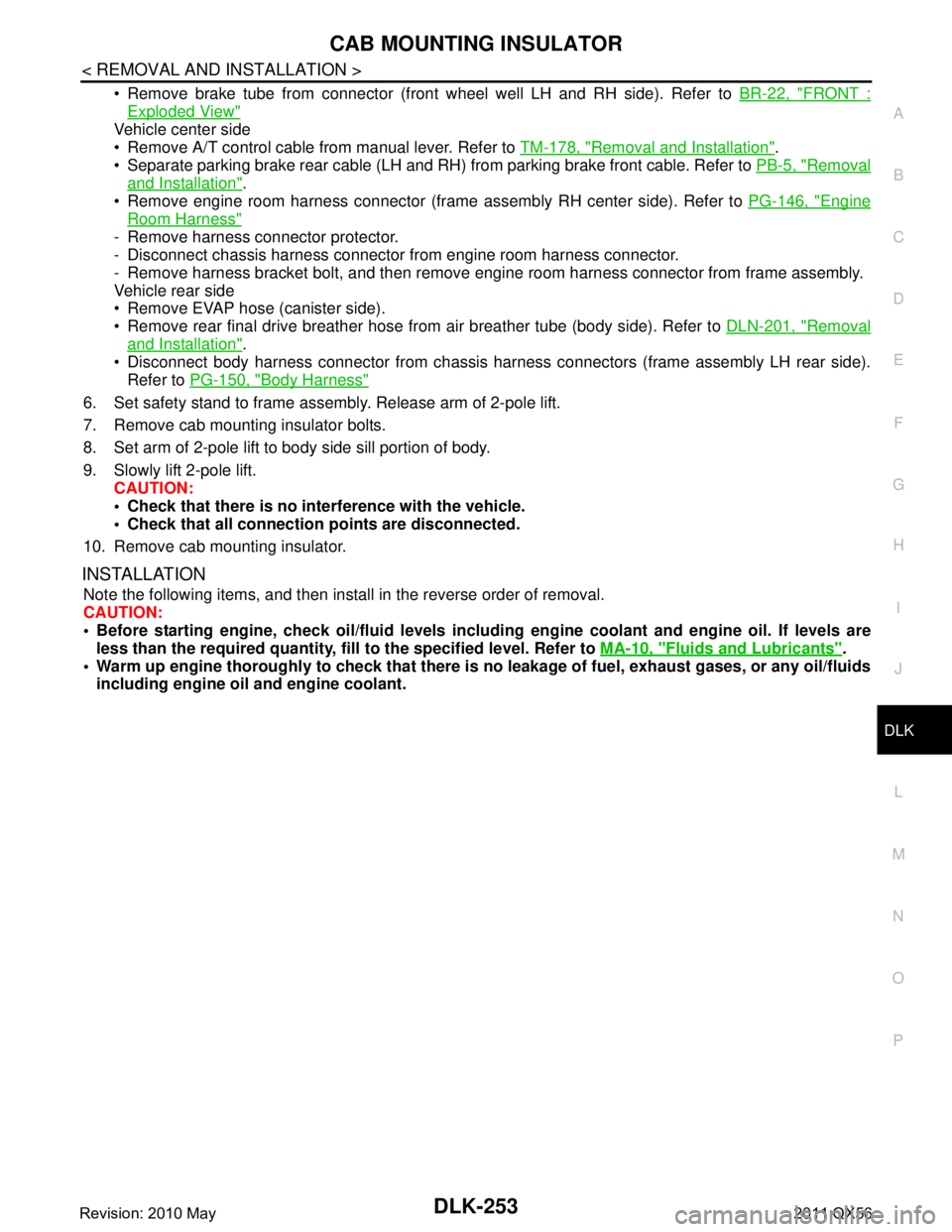
Remove brake tube from connector (front wheel well LH and RH side). Refer to BR-22, "FRONT :
Exploded View"
Vehicle center side
Remove A/T control cable from manual lever. Refer to TM-178, "
Removal and Installation".
Separate parking brake rear cable (LH and RH) from parking brake front cable. Refer to PB-5, "
Removal
and Installation".
Remove engine room harness connector (frame assembly RH center side). Refer to PG-146, "
Engine
Room Harness"
- Remove harness connector protector.
- Disconnect chassis harness connector from engine room harness connector.
- Remove harness bracket bolt, and then remove engi ne room harness connector from frame assembly.
Vehicle rear side
Remove EVAP hose (canister side).
Remove rear final drive breather hose from air breather tube (body side). Refer to DLN-201, "
Removal
and Installation".
Disconnect body harness connector from chassis harness connectors (frame assembly LH rear side).
Refer to PG-150, "
Body Harness"
6. Set safety stand to frame assembly. Release arm of 2-pole lift.
7. Remove cab mounting insulator bolts.
8. Set arm of 2-pole lift to body side sill portion of body.
9. Slowly lift 2-pole lift.
CAUTION:
Check that there is no inte rference with the vehicle.
Check that all connection points are disconnected.
10. Remove cab mounting insulator.
INSTALLATION
Note the following items, and then install in the reverse order of removal.
CAUTION:
Before starting engine, check oil/fl uid levels including engine coolant and engine oil. If levels are
less than the required quantity, fill to the specified level. Refer to MA-10, "
Fluids and Lubricants".
Warm up engine thoroughly to check that there is no leakage of fuel, exhaust gases, or any oil/fluids
including engine oil and engine coolant.
Revision: 2010 May2011 QX56