2011 INFINITI QX56 lock
[x] Cancel search: lockPage 2934 of 5598
FUEL LEVEL SENSOR UNIT, FUEL FILTER AND FUEL PUMP ASSEMBLY
FL-5
< REMOVAL AND INSTALLATION >
C
D E
F
G H
I
J
K L
M A
FL
NP
O
REMOVAL AND INSTALLATION
FUEL LEVEL SENSOR UNIT, FUEL FI
LTER AND FUEL PUMP ASSEMBLY
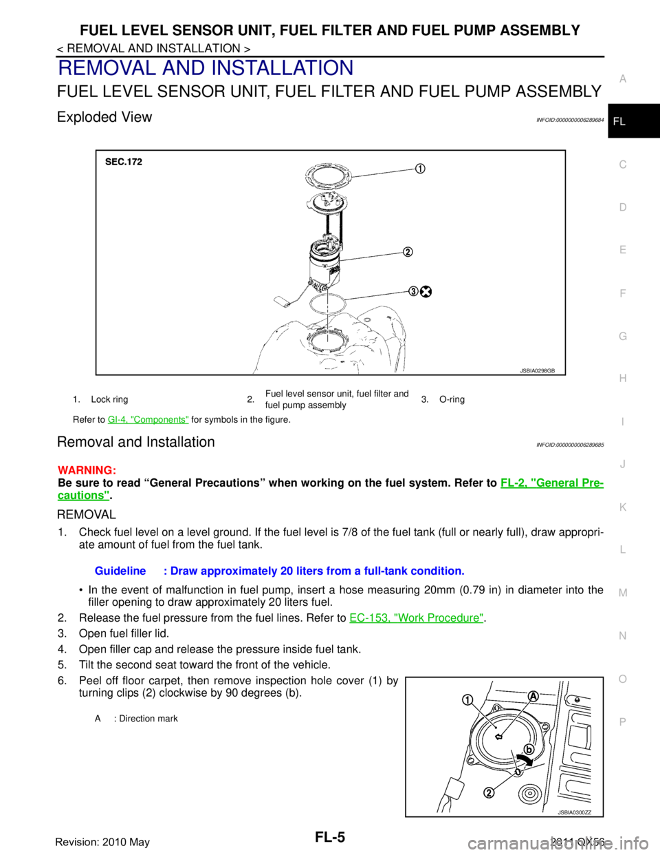
Exploded ViewINFOID:0000000006289684
Removal and InstallationINFOID:0000000006289685
WARNING:
Be sure to read “General Precautions” wh en working on the fuel system. Refer to FL-2, "
General Pre-
cautions".
REMOVAL
1. Check fuel level on a level ground. If the fuel level is 7/8 of the fuel tank (full or nearly full), draw appropri-
ate amount of fuel from the fuel tank.
In the event of malfunction in fuel pump, insert a hose measuring 20mm (0.79 in) in diameter into the
filler opening to draw approximately 20 liters fuel.
2. Release the fuel pressure from the fuel lines. Refer to EC-153, "
Work Procedure".
3. Open fuel filler lid.
4. Open filler cap and release the pressure inside fuel tank.
5. Tilt the second seat toward the front of the vehicle.
6. Peel off floor carpet, then remove inspection hole cover (1) by turning clips (2) clockwise by 90 degrees (b).
1. Lock ring 2. Fuel level sensor unit, fuel filter and
fuel pump assembly3. O-ring
Refer to GI-4, "
Components" for symbols in the figure.
JSBIA0298GB
Guideline : Draw approximately 20 li ters from a full-tank condition.
A : Direction mark
JSBIA0300ZZ
Revision: 2010 May2011 QX56
Page 2936 of 5598
FUEL LEVEL SENSOR UNIT, FUEL FILTER AND FUEL PUMP ASSEMBLY
FL-7
< REMOVAL AND INSTALLATION >
C
D E
F
G H
I
J
K L
M A
FL
NP
O
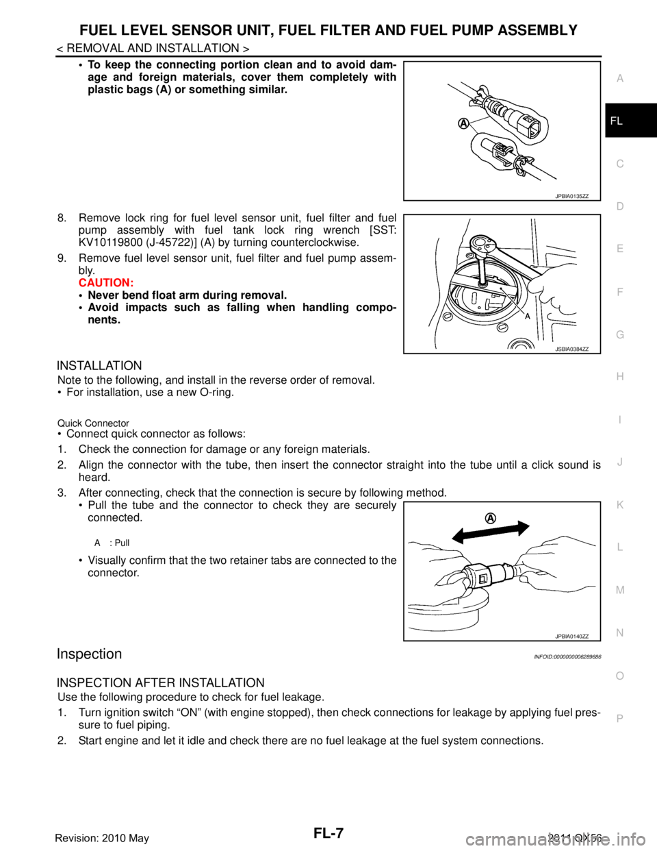
To keep the connecting portio
n clean and to avoid dam-
age and foreign materials, cover them completely with
plastic bags (A) or something similar.
8. Remove lock ring for fuel level sensor unit, fuel filter and fuel pump assembly with fuel tank lock ring wrench [SST:
KV10119800 (J-45722)] (A) by turning counterclockwise.
9. Remove fuel level sensor unit, fuel filter and fuel pump assem- bly.
CAUTION:
Never bend float arm during removal.
Avoid impacts such as fa lling when handling compo-
nents.
INSTALLATION
Note to the following, and install in the reverse order of removal.
For installation, use a new O-ring.
Quick Connector Connect quick connector as follows:
1. Check the connection for damage or any foreign materials.
2. Align the connector with the tube, then insert the connector straight into the tube until a click sound is
heard.
3. After connecting, check that the connection is secure by following method. Pull the tube and the connector to check they are securely
connected.
Visually confirm that the two retainer tabs are connected to the connector.
InspectionINFOID:0000000006289686
INSPECTION AFTER INSTALLATION
Use the following procedure to check for fuel leakage.
1. Turn ignition switch “ON” (with engine stopped), then check connections for leakage by applying fuel pres-
sure to fuel piping.
2. Start engine and let it idle and check there are no fuel leakage at the fuel system connections.
JPBIA0135ZZ
JSBIA0384ZZ
A: Pull
JPBIA0140ZZ
Revision: 2010 May2011 QX56
Page 2941 of 5598
FL-12
< REMOVAL AND INSTALLATION >
EVAP CANISTER
Removal and Installation
INFOID:0000000006414454
REMOVAL
1. Remove the spare tire.
2. Disconnect harness connectors and hoses.
3. Remove EVAP canister fixing bolt.
4. Remove EVAP canister.
NOTE:
The EVAP canister vent control valve and EVAP cont rol system pressure sensor can be removed without
removing the EVAP canister.
INSTALLATION
Install in the reverse order of removal.
NOTE:
Tighten EVAP canister fixing bolt to the specified torque.
Disassembly and AssemblyINFOID:0000000006414455
DISASSEMBLY
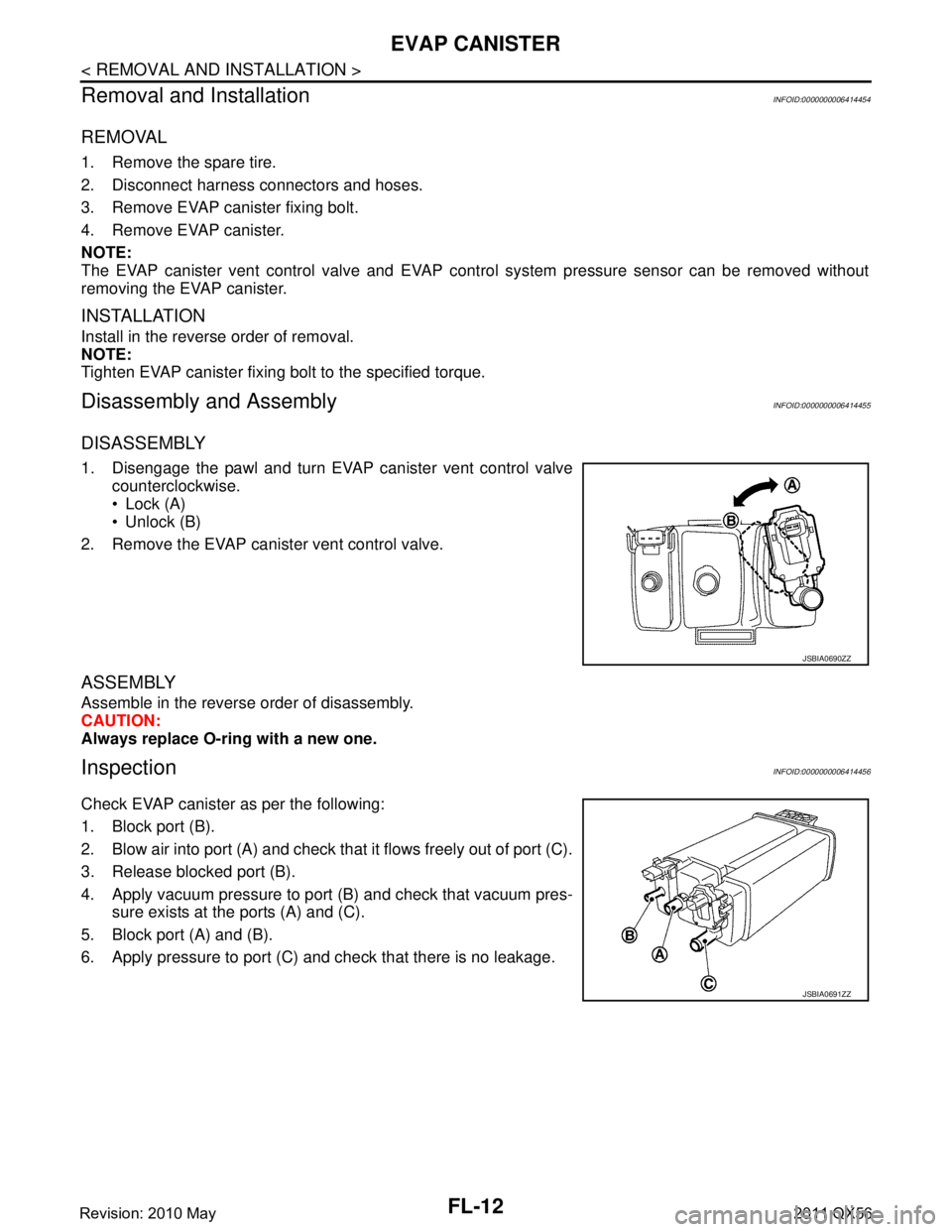
1. Disengage the pawl and turn EVAP canister vent control valve counterclockwise.
Lock (A)
Unlock (B)
2. Remove the EVAP canister vent control valve.
ASSEMBLY
Assemble in the reverse order of disassembly.
CAUTION:
Always replace O-ring with a new one.
InspectionINFOID:0000000006414456
Check EVAP canister as per the following:
1. Block port (B).
2. Blow air into port (A) and check that it flows freely out of port (C).
3. Release blocked port (B).
4. Apply vacuum pressure to port (B) and check that vacuum pres- sure exists at the ports (A) and (C).
5. Block port (A) and (B).
6. Apply pressure to port (C) and check that there is no leakage.
JSBIA0690ZZ
JSBIA0691ZZ
Revision: 2010 May2011 QX56
Page 2944 of 5598

FSU-2
< PRECAUTION >
PRECAUTIONS
PRECAUTION
PRECAUTIONS
Precaution for Supplemental Restraint System (SRS) "AIR BAG" and "SEAT BELT
PRE-TENSIONER"
INFOID:0000000006271944
The Supplemental Restraint System such as “A IR BAG” and “SEAT BELT PRE-TENSIONER”, used along
with a front seat belt, helps to reduce the risk or severi ty of injury to the driver and front passenger for certain
types of collision. This system includes seat belt switch inputs and dual stage front air bag modules. The SRS
system uses the seat belt switches to determine the front air bag deployment, and may only deploy one front
air bag, depending on the severity of a collision and w hether the front occupants are belted or unbelted.
Information necessary to service the system safely is included in the “SRS AIR BAG” and “SEAT BELT” of this
Service Manual.
WARNING:
• To avoid rendering the SRS inopera tive, which could increase the risk of personal injury or death in
the event of a collision that would result in air bag inflation, all maintenance must be performed by
an authorized NISS AN/INFINITI dealer.
Improper maintenance, including in correct removal and installation of the SRS, can lead to personal
injury caused by unintent ional activation of the system. For re moval of Spiral Cable and Air Bag
Module, see the “SRS AIR BAG”.
Do not use electrical test equipmen t on any circuit related to the SRS unless instructed to in this
Service Manual. SRS wiring harnesses can be identi fied by yellow and/or orange harnesses or har-
ness connectors.
PRECAUTIONS WHEN USING POWER TOOLS (AIR OR ELECTRIC) AND HAMMERS
WARNING:
When working near the Air Bag Diagnosis Sensor Unit or other Air Bag System sensors with the ignition ON or engine running, DO NOT use air or electric power tools or strike near the sensor(s)
with a hammer. Heavy vibration could activate the sensor(s) and deploy the air bag(s), possibly
causing serious injury.
When using air or electric power tools or hammers , always switch the ignition OFF, disconnect the
battery, and wait at least 3 minu tes before performing any service.
Precaution Necessary for Steering W heel Rotation after Battery Disconnect
INFOID:0000000006271945
NOTE:
Before removing and installing any control units, first tu rn the push-button ignition switch to the LOCK posi-
tion, then disconnect bot h battery cables.
After finishing work, confirm that all control unit connectors are connected properly, then re-connect both
battery cables.
Always use CONSULT-III to perform self-diagnosis as a part of each function inspection after finishing work.
If a DTC is detected, perform trouble diagnos is according to self-diagnosis results.
For vehicle with steering lock unit, if the battery is disconnected or discharged, the steering wheel will lock and
cannot be turned.
If turning the steering wheel is required with the bat tery disconnected or discharged, follow the operation pro-
cedure below before starting the repair operation.
OPERATION PROCEDURE
1. Connect both battery cables. NOTE:
Supply power using jumper cables if battery is discharged.
2. Turn the push-button ignition switch to ACC position. (At this time, the steering lock will be released.)
3. Disconnect both battery cables. The steering lock wi ll remain released with both battery cables discon-
nected and the steering wheel can be turned.
4. Perform the necessary repair operation.
Revision: 2010 May2011 QX56
Page 2945 of 5598
PRECAUTIONSFSU-3
< PRECAUTION >
C
DF
G H
I
J
K L
M A
B
FSU
N
O P
5. When the repair work is completed, re-connect both battery cables. With the brake pedal released, turn
the push-button ignition switch from ACC position to ON position, then to LOCK position. (The steering
wheel will lock when the push-button ignition switch is turned to LOCK position.)
6. Perform self-diagnosis check of a ll control units using CONSULT-III.
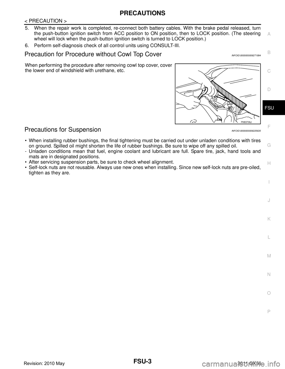
Precaution for Procedure without Cowl Top CoverINFOID:0000000006271994
When performing the procedure after removing cowl top cover, cover
the lower end of windshield with urethane, etc.
Precautions for SuspensionINFOID:0000000006225635
When installing rubber bushings, the final tightening mu st be carried out under unladen conditions with tires
on ground. Spilled oil might shorten the life of rubb er bushings. Be sure to wipe off any spilled oil.
- Unladen conditions mean that fuel, engine coolant and l ubricant are full. Spare tire, jack, hand tools and
mats are in designated positions.
After servicing suspension parts, be sure to check wheel alignment.
Self-lock nuts are not reusable. Always use new ones w hen installing. Since new self-lock nuts are pre-oiled,
tighten as they are.
PIIB3706J
Revision: 2010 May2011 QX56
Page 2951 of 5598
FRONT COIL SPRING AND SHOCK ABSORBERFSU-9
< REMOVAL AND INSTALLATION >
C
DF
G H
I
J
K L
M A
B
FSU
N
O P
REMOVAL AND INSTALLATION
FRONT COIL SPRING AND SHOCK ABSORBER
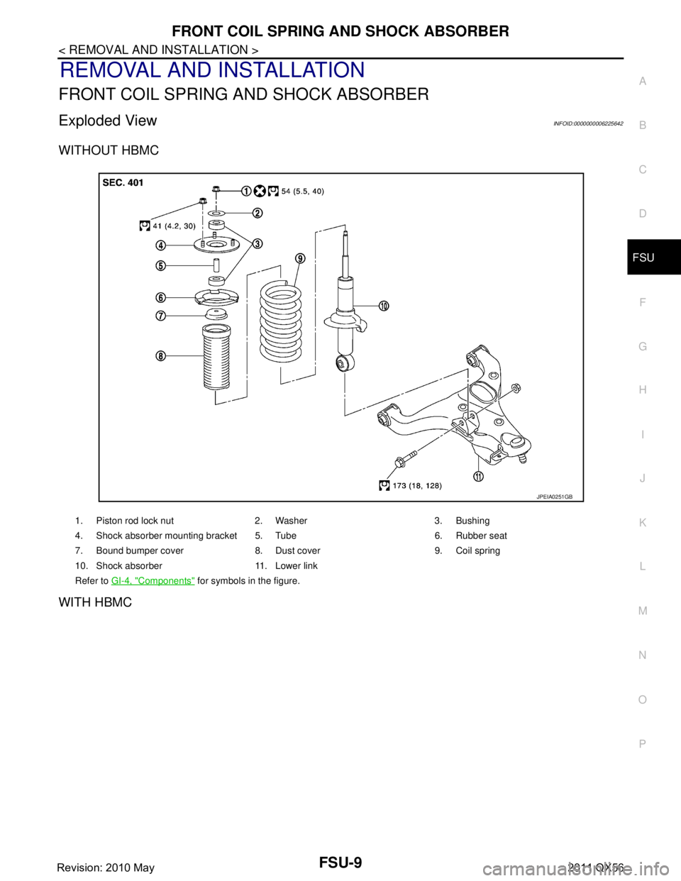
Exploded ViewINFOID:0000000006225642
WITHOUT HBMC
WITH HBMC
1. Piston rod lock nut 2. Washer 3. Bushing
4. Shock absorber mounting bracket 5. Tube 6. Rubber seat
7. Bound bumper cover 8. Dust cover 9. Coil spring
10. Shock absorber 11. Lower link
Refer to GI-4, "
Components" for symbols in the figure.
JPEIA0251GB
Revision: 2010 May2011 QX56
Page 2953 of 5598
FRONT COIL SPRING AND SHOCK ABSORBERFSU-11
< REMOVAL AND INSTALLATION >
C
DF
G H
I
J
K L
M A
B
FSU
N
O P
12. Separate drive shaft from steering knuckle. (4WD) Refer to FAX-22, "Removal and Installation".
13. Remove front tube assembly A and front tube asse mbly B from shock absorber. (With HBMC) Refer to
SCS-32, "
FRONT TUBE ASSEMBLY : Removal and Installation".
14. Remove shock absorber.
15. Perform inspection after removal. (With HBMC) Refer to FSU-12, "
Inspection and Adjustment".
INSTALLATION
Note the following, and install in the reverse order of removal.
Never tap on the ball joint cap of the stabilizer connecting rod with a hammer or a similar item when inserting
the stabilizer connecting rod into the lower link. (Without HBMC)
Perform final tightening of bolts and nuts at the shock absorber lower side (rubber bushing), under unladen
conditions with tires on level ground.
Perform inspection after installation. Refer to FSU-12, "
Inspection and Adjustment".
Perform adjustment after installation. (With HBMC) Refer to FSU-12, "
Inspection and Adjustment".
After replacing the shock absorber, always follow the disposal procedure to discard the shock absorber.
Refer to FSU-13, "
Disposal".
Disassembly and AssemblyINFOID:0000000006273960
CAUTION:
The shock absorber assembly can not be disassembled. (With HBMC)
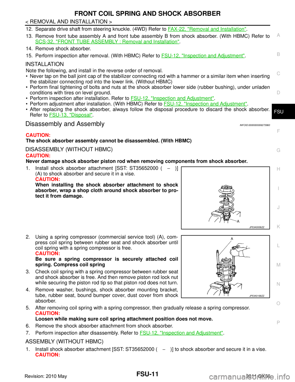
DISASSEMBLY (WITHOUT HBMC)
CAUTION:
Never damage shock absorber piston rod wh en removing components from shock absorber.
1. Install shock absorber attachment [SST: ST35652000 ( −)]
(A) to shock absorber and secure it in a vise.
CAUTION:
When installing the shock ab sorber attachment to shock
absorber, wrap a shop cloth around shock absorber to pro-
tect it from damage.
2. Using a spring compressor (commercial service tool) (A), com- press coil spring between rubber seat and shock absorber until
coil spring with a spring compressor is free.
CAUTION:
Be sure a spring compresso r is securely attached coil
spring. Compress coil spring
3. Check coil spring with a spring compressor between rubber seat and shock absorber is free. And then remove piston rod lock nut
while securing the piston rod tip so that piston rod does not turn.
4. Remove washer, bushings, shock absorber mounting bracket, tube, rubber seat, bound bumper cover, dust cover from shock
absorber.
5. After removing coil spring with a spring compressor, then gradually release a spring compressor. CAUTION:
Loosen while making sure coil spri ng attachment position does not move.
6. Remove the shock absorber at tachment from shock absorber.
7. Perform inspection after disassembly. Refer to FSU-12, "
Inspection and Adjustment".
ASSEMBLY (WITHOUT HBMC)
1. Install shock absorber attachment [SST: ST35652000 ( −)] to shock absorber and secure it in a vise.
CAUTION:
JPEIA0006ZZ
JPEIA0168ZZ
Revision: 2010 May2011 QX56
Page 2954 of 5598
FSU-12
< REMOVAL AND INSTALLATION >
FRONT COIL SPRING AND SHOCK ABSORBER
When installing the shock absorber attachment to shock absorber, wrap a shop cloth around
shock absorber to protect it from damage.
2. Compress coil spring using a spring compressor (commercial service tool), and install it onto shock absorber.
CAUTION:
Be sure a spring compressor is securely attach ed to coil spring. Compress coil spring.
Set coil spring so that its paint marks face downward.
3. Apply soapy water to dust cover. CAUTION:
Never use machine oil.
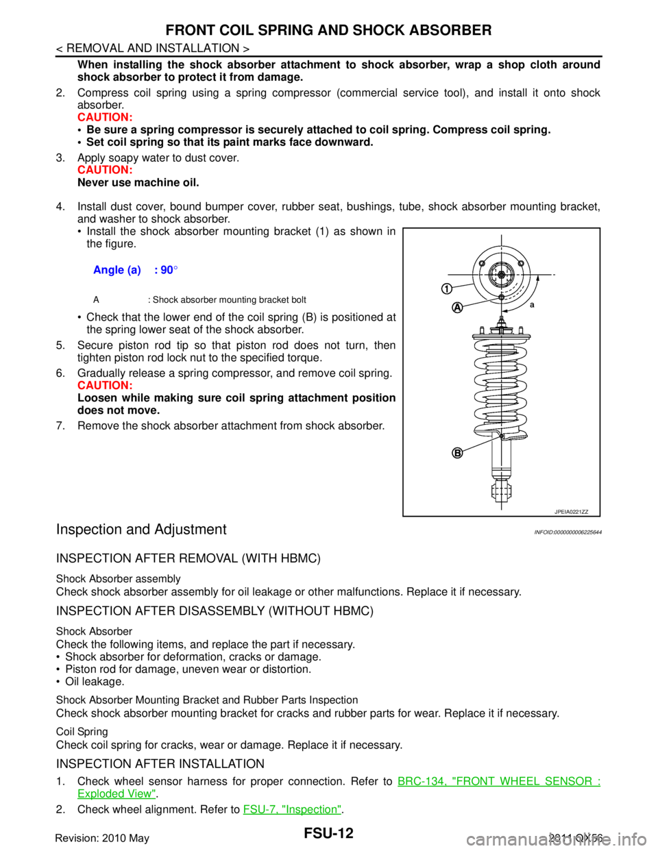
4. Install dust cover, bound bumper cover, rubber seat , bushings, tube, shock absorber mounting bracket,
and washer to shock absorber.
Install the shock absorber mounting bracket (1) as shown in the figure.
Check that the lower end of the coil spring (B) is positioned at the spring lower seat of the shock absorber.
5. Secure piston rod tip so that piston rod does not turn, then tighten piston rod lock nut to the specified torque.
6. Gradually release a spring compressor, and remove coil spring. CAUTION:
Loosen while making sure co il spring attachment position
does not move.
7. Remove the shock absorber attachment from shock absorber.
Inspection and AdjustmentINFOID:0000000006225644
INSPECTION AFTER REMOVAL (WITH HBMC)
Shock Absorber assembly
Check shock absorber assembly for oil leakage or other malfunctions. Replace it if necessary.
INSPECTION AFTER DISASSEMBLY (WITHOUT HBMC)
Shock Absorber
Check the following items, and replace the part if necessary.
Shock absorber for deformation, cracks or damage.
Piston rod for damage, uneven wear or distortion.
Oil leakage.
Shock Absorber Mounting Bracket and Rubber Parts Inspection
Check shock absorber mounting bracket for cracks and rubber parts for wear. Replace it if necessary.
Coil Spring
Check coil spring for cracks, wear or damage. Replace it if necessary.
INSPECTION AFTER INSTALLATION
1. Check wheel sensor harness for proper connection. Refer to BRC-134, "FRONT WHEEL SENSOR :
Exploded View".
2. Check wheel alignment. Refer to FSU-7, "
Inspection".
Angle (a) : 90
°
A : Shock absorber mounting bracket bolt
JPEIA0221ZZ
Revision: 2010 May2011 QX56