2011 INFINITI QX56 lock
[x] Cancel search: lockPage 3004 of 5598
GI-40
< BASIC INSPECTION >
SERVICE INFORMATION FOR ELECTRICAL INCIDENT
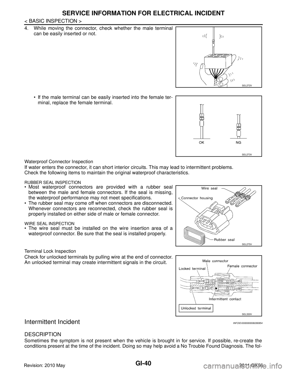
4. While moving the connector, check whether the male terminalcan be easily inserted or not.
If the male terminal can be easily inserted into the female ter-minal, replace the female terminal.
Waterproof Connector Inspection
If water enters the connector, it can short interior circuits. This may lead to intermittent problems.
Check the following items to maintain the original waterproof characteristics.
RUBBER SEAL INSPECTION Most waterproof connectors are provided with a rubber seal between the male and female connectors. If the seal is missing,
the waterproof performance may not meet specifications.
The rubber seal may come off when connectors are disconnected.
Whenever connectors are reconnected, check the rubber seal is
properly installed on either side of male or female connector.
WIRE SEAL INSPECTION The wire seal must be installed on the wire insertion area of awaterproof connector. Be sure that the seal is installed properly.
Terminal Lock Inspection
Check for unlocked terminals by pulling wire at the end of connector.
An unlocked terminal may create intermittent signals in the circuit.
Intermittent IncidentINFOID:0000000006280854
DESCRIPTION
Sometimes the symptom is not present when the vehicle is brought in for service. If possible, re-create the
conditions present at the time of the incident. Doing so may help avoid a No Trouble Found Diagnosis. The fol-
SEL272V
SEL273V
SEL275V
SEL330V
Revision: 2010 May2011 QX56
Page 3007 of 5598
SERVICE INFORMATION FOR ELECTRICAL INCIDENTGI-43
< BASIC INSPECTION >
C
DE
F
G H
I
J
K L
M B
GI
N
O P
Circuit InspectionINFOID:0000000006280855
DESCRIPTION
In general, testing electrical circuits is an easy task if it is approached in a logical and organized method. Before beginning it is important to have all available information on the system to be tested. Also, get a thor-
ough understanding of system operation. Then you will be able to use the appropriate equipment and follow
the correct test procedure.
You may have to simulate vehicle vibrations while te sting electrical components. Gently shake the wiring
harness or electrical component to do this.
NOTE:
Refer to GI-37, "
How to Check Terminal" to probe or check terminal.
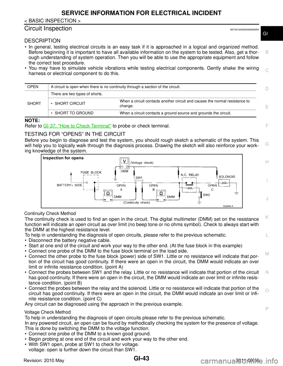
TESTING FOR “OPENS” IN THE CIRCUIT
Before you begin to diagnose and test the system, you should rough sketch a schematic of the system. This
will help you to logically walk through the diagnosis process. Drawing the sketch will also reinforce your work-
ing knowledge of the system.
Continuity Check Method
The continuity check is used to find an open in the circui t. The digital multimeter (DMM) set on the resistance
function will indicate an open circuit as over limit (no beep tone or no ohms symbol). Check to always start with
the DMM at the highest resistance level.
To help in understanding the diagnosis of open circui ts, please refer to the previous schematic.
Disconnect the battery negative cable.
Start at one end of the circuit and work your way to the other end. (At the fuse block in this example)
Connect one probe of the DMM to the fuse block terminal on the load side.
Connect the other probe to the fuse block (power) side of SW1. Little or no resistance will indicate that por-
tion of the circuit has good continuity. If there were an open in the circuit, the DMM would indicate an over
limit or infinite resistance condition. (point A)
Connect the probes between SW1 and the relay. Little or no resistance will indicate that portion of the circuit
has good continuity. If there were an open in the circuit, t he DMM would indicate an over limit or infinite resis-
tance condition. (point B)
Connect the probes between the relay and the solenoid. Little or no resistance will indicate that portion of the
circuit has good continuity. If there were an open in the ci rcuit, the DMM would indicate an over limit or infi-
nite resistance condition. (point C)
Any circuit can be diagnosed using the approach in the previous example.
Voltage Check Method
To help in understanding the diagnosis of open circui ts please refer to the previous schematic.
In any powered circuit, an open can be found by methodica lly checking the system for the presence of voltage.
This is done by switching the DMM to the voltage function.
Connect one probe of the DMM to a known good ground.
Begin probing at one end of the circuit and work your way to the other end.
With SW1 open, probe at SW1 to check for voltage. voltage: open is further down the circuit than SW1.
OPEN A circuit is open when there is no continuity through a section of the circuit.
SHORT There are two types of shorts.
SHORT CIRCUIT
When a circuit contacts another circuit and causes the normal resistance to
change.
SHORT TO GROUND When a circuit contacts a ground source and grounds the circuit.
SGI846-A
Revision: 2010 May2011 QX56
Page 3008 of 5598
GI-44
< BASIC INSPECTION >
SERVICE INFORMATION FOR ELECTRICAL INCIDENT
no voltage: open is between fuse block and SW1 (point A).
Close SW1 and probe at relay. voltage: open is further down the circuit than the relay.
no voltage: open is between SW1 and relay (point B).
Close the relay and probe at the solenoid. voltage: open is further down the circuit than the solenoid.
no voltage: open is between relay and solenoid (point C).
Any powered circuit can be diagnosed using the approach in the previous example.
TESTING FOR “SHORTS” IN THE CIRCUIT
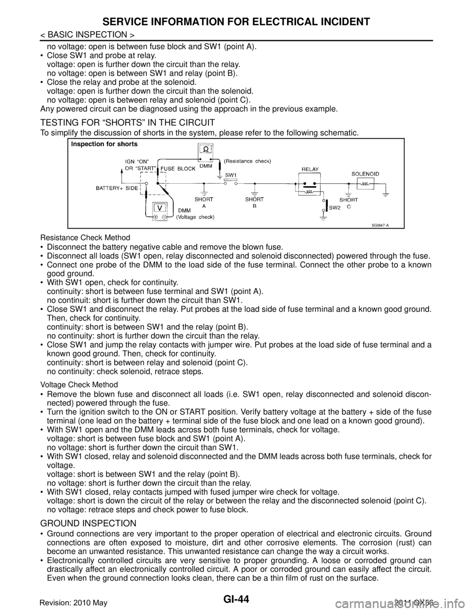
To simplify the discussion of shorts in the sy stem, please refer to the following schematic.
Resistance Check Method
Disconnect the battery negative cable and remove the blown fuse.
Disconnect all loads (SW1 open, relay disconnected and solenoid disconnected) powered through the fuse.
Connect one probe of the DMM to the load side of the fuse terminal. Connect the other probe to a known
good ground.
With SW1 open, check for continuity. continuity: short is between fuse terminal and SW1 (point A).
no continuit: short is further down the circuit than SW1.
Close SW1 and disconnect the relay. Put probes at the load side of fuse terminal and a known good ground. Then, check for continuity.
continuity: short is between SW1 and the relay (point B).
no continuity: short is further down the circuit than the relay.
Close SW1 and jump the relay contacts with jumper wir e. Put probes at the load side of fuse terminal and a
known good ground. Then, check for continuity.
continuity: short is between relay and solenoid (point C).
no continuity: check solenoid, retrace steps.
Voltage Check Method
Remove the blown fuse and disconnect all loads (i .e. SW1 open, relay disconnected and solenoid discon-
nected) powered through the fuse.
Turn the ignition switch to the ON or START position. Verify battery voltage at the battery + side of the fuse
terminal (one lead on the battery + terminal side of the fuse block and one lead on a known good ground).
With SW1 open and the DMM leads across both fuse terminals, check for voltage. voltage: short is between fuse block and SW1 (point A).
no voltage: short is further down the circuit than SW1.
With SW1 closed, relay and solenoid disconnected and the DMM leads across both fuse terminals, check for
voltage.
voltage: short is between SW1 and the relay (point B).
no voltage: short is further down the circuit than the relay.
With SW1 closed, relay contacts jumped with fused jumper wire check for voltage. voltage: short is down the circuit of the relay or between the relay and the disconnected solenoid (point C).
no voltage: retrace steps and check power to fuse block.
GROUND INSPECTION
Ground connections are very important to the proper operation of electrical and electronic circuits. Ground
connections are often exposed to moisture, dirt and other corrosive elements. The corrosion (rust) can
become an unwanted resistance. This unwanted resistance can change the way a circuit works.
Electronically controlled circuits are very sens itive to proper grounding. A loose or corroded ground can
drastically affect an electronically controlled circuit. A poor or corroded ground can easily affect the circuit.
Even when the ground connection looks clean, there c an be a thin film of rust on the surface.
SGI847-A
Revision: 2010 May2011 QX56
Page 3029 of 5598
INSPECTION AND ADJUSTMENTGI-65
< BASIC INSPECTION >
C
DE
F
G H
I
J
K L
M B
GI
N
O PINSPECTION AND ADJUSTMENT
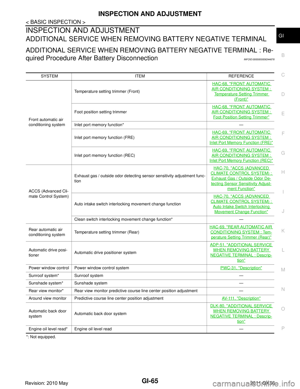
ADDITIONAL SERVICE WHEN REMOVING BATTERY NEGATIVE TERMINAL
ADDITIONAL SERVICE WHEN REMOVING BATTERY NEGATIVE TERMINAL : Re-
quired Procedure After Battery Disconnection
INFOID:0000000006344676
*: Not equipped. SYSTEM ITEM REFERENCE
Front automatic air
conditioning system Temperature setting trimmer (Front)
HAC-68, "
FRONT AUTOMATIC
AIR CONDITIONING SYSTEM :
Temperature Setting Trimmer
(Front)"
Foot position setting trimmer
HAC-68, "
FRONT AUTOMATIC
AIR CONDITIONING SYSTEM :
Foot Position Setting Trimmer"
Inlet port memory function* —
Inlet port memory function (FRE)
HAC-69, "
FRONT AUTOMATIC
AIR CONDITIONING SYSTEM :
Inlet Port Memory
Function (FRE)"
Inlet port memory function (REC) HAC-69, "
FRONT AUTOMATIC
AIR CONDITIONING SYSTEM :
Inlet Port Memory Function (REC)"
ACCS (Advanced Cli-
mate Control System)Exhaust gas / outside odor detecting sensor sensitivity adjustment func-
tion
HAC-70, "
ACCS (ADVANCED
CLIMATE CONTROL SYSTEM) :
Exhaust Gas / Outside Odor De-
tecting Sensor Sensitivity Adjust-
ment Function"
Auto intake switch interlocking movement change function
HAC-70, "
ACCS (ADVANCED
CLIMATE CONTROL SYSTEM) :
Auto Intake Switch Interlocking
Movement Change Function"
Clean switch interlocking movement change function* —
Rear automatic air
conditioning system Temperature setting trimmer (Rear) HAC-69, "
REAR AUTOMATIC AIR
CONDITIONING SYSTEM : Tem-
perature Setting
Trimmer (Rear)"
Automatic drive posi-
tioner Automatic drive positioner system ADP-51, "
ADDITIONAL SERVICE
WHEN REMOVING BATTERY
NEGATIVE TERMINAL : Descrip-
tion"
Power window control Power window control system
PWC-31, "Description"
Sunroof system* Sunroof system —
Sunshade system* Sunshade system —
Rear view monitor* Rear view monitor predictive course line center position adjustment —
Around view monitor Predictive course line center position adjustment AV- 111 , "
Description"
Automatic back door
systemAutomatic back door system DLK-80, "
ADDITIONAL SERVICE
WHEN REMOVING BATTERY
NEGATIVE TERMINAL : Descrip-
tion"
Engine oil level read* Engine oil level read —
Revision: 2010 May2011 QX56
Page 3031 of 5598

GW-2
< PRECAUTION >
PRECAUTIONS
PRECAUTION
PRECAUTIONS
Precaution for Supplemental Restraint System (SRS) "AIR BAG" and "SEAT BELT
PRE-TENSIONER"
INFOID:0000000006257243
The Supplemental Restraint System such as “A IR BAG” and “SEAT BELT PRE-TENSIONER”, used along
with a front seat belt, helps to reduce the risk or severi ty of injury to the driver and front passenger for certain
types of collision. This system includes seat belt switch inputs and dual stage front air bag modules. The SRS
system uses the seat belt switches to determine the front air bag deployment, and may only deploy one front
air bag, depending on the severity of a collision and w hether the front occupants are belted or unbelted.
Information necessary to service the system safely is included in the “SRS AIR BAG” and “SEAT BELT” of this
Service Manual.
WARNING:
• To avoid rendering the SRS inopera tive, which could increase the risk of personal injury or death in
the event of a collision that would result in air bag inflation, all maintenance must be performed by
an authorized NISS AN/INFINITI dealer.
Improper maintenance, including in correct removal and installation of the SRS, can lead to personal
injury caused by unintent ional activation of the system. For re moval of Spiral Cable and Air Bag
Module, see the “SRS AIR BAG”.
Do not use electrical test equipmen t on any circuit related to the SRS unless instructed to in this
Service Manual. SRS wiring harnesses can be identi fied by yellow and/or orange harnesses or har-
ness connectors.
PRECAUTIONS WHEN USING POWER TOOLS (AIR OR ELECTRIC) AND HAMMERS
WARNING:
When working near the Air Bag Diagnosis Sensor Unit or other Air Bag System sensors with the ignition ON or engine running, DO NOT use air or electric power tools or strike near the sensor(s)
with a hammer. Heavy vibration could activate the sensor(s) and deploy the air bag(s), possibly
causing serious injury.
When using air or electric power tools or hammers , always switch the ignition OFF, disconnect the
battery, and wait at least 3 minu tes before performing any service.
Precaution Necessary for Steering W heel Rotation after Battery Disconnect
INFOID:0000000006257244
NOTE:
Before removing and installing any control units, first tu rn the push-button ignition switch to the LOCK posi-
tion, then disconnect bot h battery cables.
After finishing work, confirm that all control unit connectors are connected properly, then re-connect both
battery cables.
Always use CONSULT-III to perform self-diagnosis as a part of each function inspection after finishing work.
If a DTC is detected, perform trouble diagnos is according to self-diagnosis results.
For vehicle with steering lock unit, if the battery is disconnected or discharged, the steering wheel will lock and
cannot be turned.
If turning the steering wheel is required with the bat tery disconnected or discharged, follow the operation pro-
cedure below before starting the repair operation.
OPERATION PROCEDURE
1. Connect both battery cables. NOTE:
Supply power using jumper cables if battery is discharged.
2. Turn the push-button ignition switch to ACC position. (At this time, the steering lock will be released.)
3. Disconnect both battery cables. The steering lock wi ll remain released with both battery cables discon-
nected and the steering wheel can be turned.
4. Perform the necessary repair operation.
Revision: 2010 May2011 QX56
Page 3032 of 5598
PRECAUTIONSGW-3
< PRECAUTION >
C
DE
F
G H
I
J
L
M A
B
GW
N
O P
5. When the repair work is completed, re-connect both battery cables. With the brake pedal released, turn
the push-button ignition switch from ACC position to ON position, then to LOCK position. (The steering
wheel will lock when the push-button ignition switch is turned to LOCK position.)
6. Perform self-diagnosis check of a ll control units using CONSULT-III.
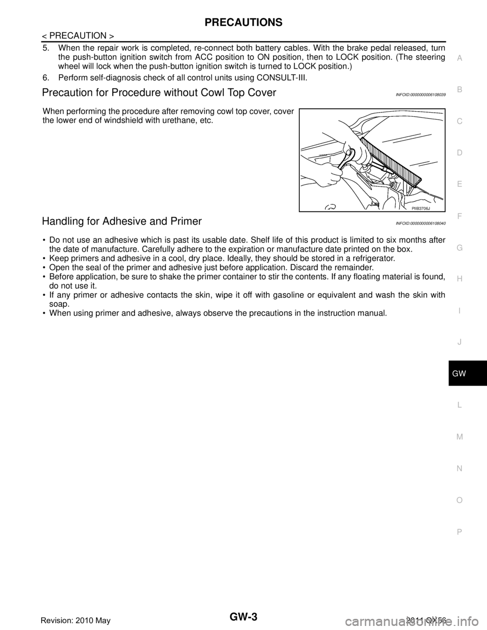
Precaution for Procedure without Cowl Top CoverINFOID:0000000006108039
When performing the procedure after removing cowl top cover, cover
the lower end of windshield with urethane, etc.
Handling for Adhesive and PrimerINFOID:0000000006108040
Do not use an adhesive which is past its usable date. Shel f life of this product is limited to six months after
the date of manufacture. Carefully adhere to the ex piration or manufacture date printed on the box.
Keep primers and adhesive in a cool, dry place. I deally, they should be stored in a refrigerator.
Open the seal of the primer and adhesive just before application. Discard the remainder.
Before application, be sure to shake the primer container to stir the contents. If any floating material is found,
do not use it.
If any primer or adhesive contacts the skin, wipe it off with gasoline or equivalent and wash the skin with
soap.
When using primer and adhesive, always observe the precautions in the instruction manual.
PIIB3706J
Revision: 2010 May2011 QX56
Page 3034 of 5598
SQUEAK AND RATTLE TROUBLE DIAGNOSESGW-5
< SYMPTOM DIAGNOSIS >
C
DE
F
G H
I
J
L
M A
B
GW
N
O P
SYMPTOM DIAGNOSIS
SQUEAK AND RATTLE TROUBLE DIAGNOSES
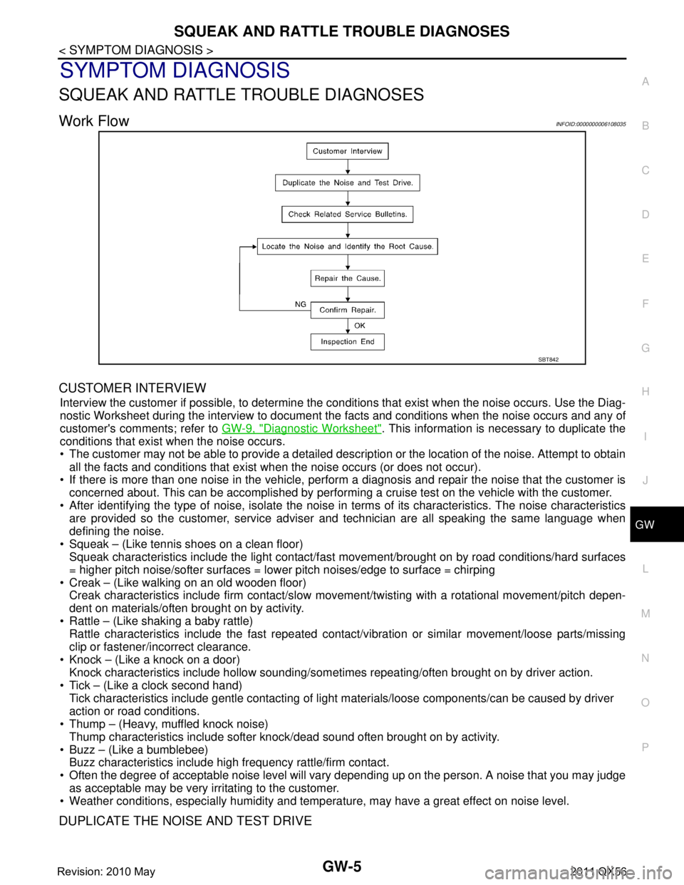
Work FlowINFOID:0000000006108035
CUSTOMER INTERVIEW
Interview the customer if possible, to determine the conditions that exist when the noise occurs. Use the Diag-
nostic Worksheet during the interview to document t he facts and conditions when the noise occurs and any of
customer's comments; refer to GW-9, "
Diagnostic Worksheet". This information is necessary to duplicate the
conditions that exist when the noise occurs.
The customer may not be able to provide a detailed description or the location of the noise. Attempt to obtain
all the facts and conditions that exist when the noise occurs (or does not occur).
If there is more than one noise in the vehicle, perform a diagnosis and repair the noise that the customer is
concerned about. This can be accomplished by performing a cruise test on the vehicle with the customer.
After identifying the type of noise, isolate the noise in terms of its characteristics. The noise characteristics
are provided so the customer, service adviser and technician are all speaking the same language when
defining the noise.
Squeak – (Like tennis shoes on a clean floor) Squeak characteristics include the light contact/fast movement/brought on by road conditions/hard surfaces
= higher pitch noise/softer surfaces = lower pitch noises/edge to surface = chirping
Creak – (Like walking on an old wooden floor) Creak characteristics include firm contact/slow mo vement/twisting with a rotational movement/pitch depen-
dent on materials/often brought on by activity.
Rattle – (Like shaking a baby rattle) Rattle characteristics include the fast repeated contac t/vibration or similar movement/loose parts/missing
clip or fastener/incorrect clearance.
Knock – (Like a knock on a door) Knock characteristics include hollow sounding/someti mes repeating/often brought on by driver action.
Tick – (Like a clock second hand) Tick characteristics include gentle contacting of li ght materials/loose components/can be caused by driver
action or road conditions.
Thump – (Heavy, muffled knock noise)
Thump characteristics include softer k nock/dead sound often brought on by activity.
Buzz – (Like a bumblebee) Buzz characteristics include high frequency rattle/firm contact.
Often the degree of acceptable noise level will vary depending up on the person. A noise that you may judge
as acceptable may be very irritating to the customer.
Weather conditions, especially humidity and temperat ure, may have a great effect on noise level.
DUPLICATE THE NOISE AND TEST DRIVE
SBT842
Revision: 2010 May2011 QX56
Page 3035 of 5598

GW-6
< SYMPTOM DIAGNOSIS >
SQUEAK AND RATTLE TROUBLE DIAGNOSES
If possible, drive the vehicle with the customer until the noise is duplicated. Note any additional information on
the Diagnostic Worksheet regarding the conditions or lo cation of the noise. This information can be used to
duplicate the same conditions when you confirm the repair.
If the noise can be duplicated easily during the test drive, to help identify the source of the noise, try to dupli-
cate the noise with the vehicle stopped by doing one or all of the following:
1) Close a door.
2) Tap or push/pull around the area where the noise appears to be coming from.
3) Rev the engine.
4) Use a floor jack to recreate vehicle “twist”.
5) At idle, apply engine load (electrical load, half-cl utch on M/T models, drive position on A/T models).
6) Raise the vehicle on a hoist and hit a tire with a rubber hammer.
Drive the vehicle and attempt to duplicate the conditions the customer states exist when the noise occurs.
If it is difficult to duplicate the noise, drive the v ehicle slowly on an undulating or rough road to stress the
vehicle body.
CHECK RELATED SERVICE BULLETINS
After verifying the customer concern or symptom, chec k ASIST for Technical Service Bulletins (TSBs) related
to that concern or symptom.
If a TSB relates to the symptom, follo w the procedure to repair the noise.
LOCATE THE NOISE AND IDENTIFY THE ROOT CAUSE
1. Narrow down the noise to a general area. To help pi npoint the source of the noise, use a listening tool
(Chassis Ear: J-39570, Engine Ear and mechanics stethoscope).
2. Narrow down the noise to a more specific area and identify the cause of the noise by:
Removing the components in the area that you suspect the noise is coming from.
Do not use too much force when removing clips and fasteners, otherwise clips and fastener can be broken
or lost during the repair, resulting in the creation of new noise.
Tapping or pushing/pulling the component that you suspect is causing the noise.
Do not tap or push/pull the component with excessive force, otherwise the noise will be eliminated only tem-
porarily.
Feeling for a vibration with your hand by touching the component(s) that you suspect is (are) causing the
noise.
Placing a piece of paper between components that you suspect are causing the noise.
Looking for loose components and contact marks. Refer to GW-7, "
Inspection Procedure".
REPAIR THE CAUSE
If the cause is a loose component, tighten the component securely.
If the cause is insufficient clearance between components:
- Separate components by repositioning or loos ening and retightening the component, if possible.
- Insulate components with a suitable insulator such as urethane pads, foam blocks, felt cloth tape or ure-
thane tape. A Nissan Squeak and Rattle Kit (J-43980) is available through your authorized Nissan Parts
Department.
CAUTION:
Do not use excessive force as many components are constructed of plastic and may be damaged.
NOTE:
Always check with the Parts Departm ent for the latest parts information.
The following materials are contained in the Nissan Squeak and Rattle Kit (J-43980). Each item can be
ordered separately as needed.
URETHANE PADS [1.5 mm (0.059 in) thick]
Insulates connectors, harness, etc.
76268-9E005: 100 ×135 mm (3.94 ×5.31 in)/76884-71L01: 60 ×85 mm (2.36 ×3.35 in)/76884-
71L02:15 ×25 mm (0.59 ×0.98 in)
INSULATOR (Foam blocks)
Insulates components from contact. Can be used to fill space behind a panel.
73982-9E000: 45 mm (1.77 in) thick, 50 ×50 mm (1.97 ×1.97 in)/73982-
50Y00: 10 mm (0.39 in) thick, 50 ×50 mm (1.97 ×1.97 in)
INSULATOR (Light foam block)
80845-71L00: 30 mm (1.18 in) thick, 30 ×50 mm (1.18 ×1.97in)
FELT CLOTHTAPE
Used to insulate where movement does not occu r. Ideal for instrument panel applications.
Revision: 2010 May2011 QX56