2011 INFINITI QX56 BATTERY
[x] Cancel search: BATTERYPage 2578 of 5598
EM-16
< BASIC INSPECTION >
COMPRESSION PRESSURE
COMPRESSION PRESSURE
InspectionINFOID:0000000006289521
1. Warm up engine thoroughly. Then, stop it.
2. Release fuel pressure. Refer to EC-153, "
Work Procedure".
CAUTION:
If CONSULT-III is not used to release fuel pr essure leave the fuel pump fuse disconnected until
step 7.
3. Remove fuel pump fuse in IPDM E/R. NOTE:
For the fuse number, refer to EC-114, "
Wiring Diagram".
For the fuse arrangement, refer to PG-143, "
Fuse, Connector and Terminal Arrangement".
4. Remove engine cover. Refer to EM-25, "
Exploded View".
5. Remove ignition coil and spark plug from each cylinder. Refer to EM-29, "
Exploded View".
6. Connect engine tachometer (not required in use of CONSULT-III).
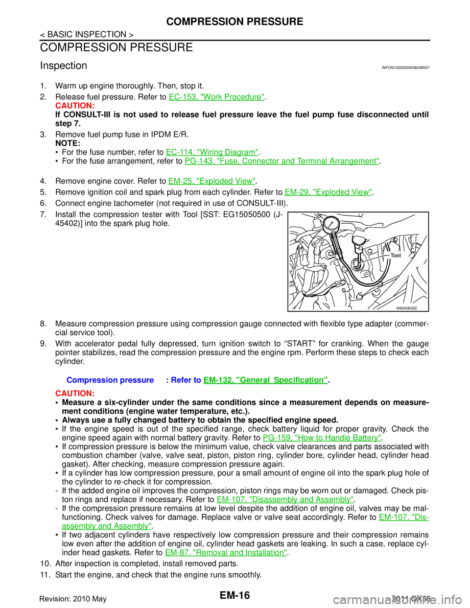
7. Install the compression tester with Tool [SST: EG15050500 (J- 45402)] into the spark plug hole.
8. Measure compression pressure using compressi on gauge connected with flexible type adapter (commer-
cial service tool).
9. With accelerator pedal fully depressed, turn ignition switch to “START” for cranking. When the gauge pointer stabilizes, read the compression pressure and the engine rpm. Perform these steps to check each
cylinder.
CAUTION:
Measure a six-cylinder under the same conditio ns since a measurement depends on measure-
ment conditions (engine water temperature, etc.).
Always use a fully changed battery to obtain the specified engine speed.
If the engine speed is out of the specified range, c heck battery liquid for proper gravity. Check the
engine speed again with normal battery gravity. Refer to PG-159, "
How to Handle Battery".
If compression pressure is below the minimum value, check valve clearances and parts associated with combustion chamber (valve, valve seat, piston, pi ston ring, cylinder bore, cylinder head, cylinder head
gasket). After checking, measure compression pressure again.
If a cylinder has low compression pressure, pour a small amount of engine oil into the spark plug hole of the cylinder to re-check it for compression.
- If the added engine oil improves the compression, pi ston rings may be worn out or damaged. Check pis-
ton rings and replace if necessary. Refer to EM-107, "
Disassembly and Assembly".
- If the compression pressure remains at low level despite the addition of engine oil, valves may be mal- functioning. Check valves for damage. Replace valve or valve seat accordingly. Refer to EM-107, "
Dis-
assembly and Assembly".
If two adjacent cylinders have respectively low co mpression pressure and their compression remains
low even after the addition of engine oil, cylinder head gaskets are leaking. In such a case, replace cyl-
inder head gaskets. Refer to EM-87, "
Removal and Installation".
10. After inspection is completed, install removed parts.
11. Start the engine, and check that the engine runs smoothly.
WBIA0605E
Compression pressure : Refer to EM-132, "GeneralSpecification".
Revision: 2010 May2011 QX56
Page 2606 of 5598
EM-44
< REMOVAL AND INSTALLATION >
HIGH PRESSURE FUEL PUMP AND FUEL HOSE
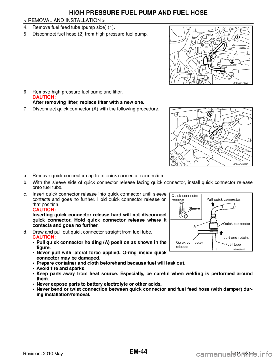
4. Remove fuel feed tube (pump side) (1).
5. Disconnect fuel hose (2) from high pressure fuel pump.
6. Remove high pressure fuel pump and lifter.CAUTION:
After removing lifter, replace lifter with a new one.
7. Disconnect quick connector (A) with the following procedure.
a. Remove quick connector cap from quick connector connection.
b. With the sleeve side of quick connector release facing quick connector, install quick connector release
onto fuel tube.
c. Insert quick connector release into quick connector until sleeve contacts and goes no further. Hold quick connector release on
that position.
CAUTION:
Inserting quick connector re lease hard will not disconnect
quick connector. Hold qui ck connector release where it
contacts and goes no further.
d. Draw and pull out quick connector straight from fuel tube. CAUTION:
Pull quick connector holding (A) position as shown in thefigure.
Never pull with lateral force applied. O-ring inside quick
connector may be damaged.
Prepare container and cloth befo rehand because fuel will leak out.
Avoid fire and sparks.
Keep parts away from heat source. Especially, be careful when welding is performed around
them.
Never expose parts to battery electrolyte or other acids.
Never bend or twist connection between quick c onnector and fuel feed hose (with damper) dur-
ing installation/removal.
JPBIA3479ZZ
JPBIA3493ZZ
KBIA0702E
Revision: 2010 May2011 QX56
Page 2661 of 5598
ENGINE ASSEMBLYEM-99
< UNIT REMOVAL AND INSTALLATION >
C
DE
F
G H
I
J
K L
M A
EM
NP
O
4WD models
Removal and InstallationINFOID:0000000006289577
WARNING:
Situate the vehicle on a flat and solid surface.
Place chocks at the front
and back of rear wheels.
For engines not equipped with engi ne slingers, attach proper slingers and bolts described in PARTS
CATALOG.
CAUTION:
Always be careful to work safely, and avo id forceful or uninstructed operations.
Never start working until exhaust system and engine coolant are cool enough.
If items or work required are not covered by th e engine section, refer to the applicable sections.
Always use the support poin t specified for lifting.
Use either 2-pole lift type or separate type lift as much as possible. If board-on type is used for
unavoidable reasons, support at r ear axle jacking point with transmi ssion jack or similar tool before
starting work, in preparat ion for the backward shift of the center of gravity.
For supporting points fo r lifting and jacking point at rear axle, refer to GI-32, "
Garage Jack and
Safety Stand".
NOTE:
When removing/installing only the engine mounting, the hold engine assembly as instructed bellow:
1. Remove hood assembly. Refer to DLK-215, "
Exploded View".
2. Remove the following components and related parts: Battery. Refer to PG-164, "
Exploded View".
Battery tray.
Power steering reservoir tank bracket. Refer to ST-54, "
Exploded View".
Air cleaner case assembly and air duct. Refer to EM-27, "
Exploded View".
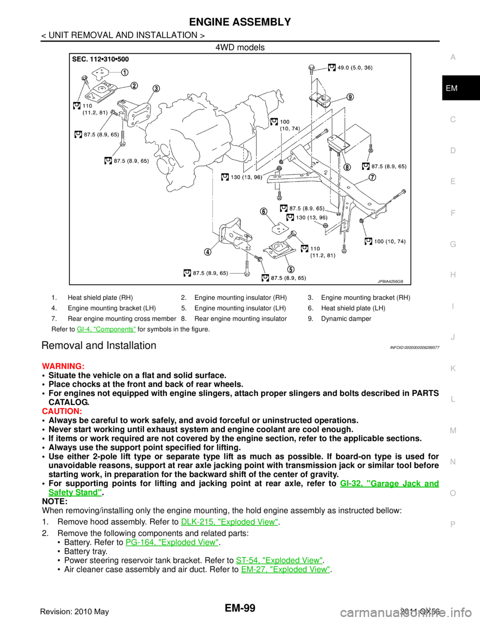
JPBIA4256GB
1. Heat shield plate (RH) 2. Engine mounting insulator (RH) 3. Engine mounting bracket (RH)
4. Engine mounting bracket (LH) 5. Engine mounting insulator (LH) 6. Heat shield plate (LH)
7. Rear engine mounting cross member 8. Rear engine mounting insulator 9. Dynamic damper
Refer to GI-4, "
Components" for symbols in the figure.
Revision: 2010 May2011 QX56
Page 2662 of 5598
EM-100
< UNIT REMOVAL AND INSTALLATION >
ENGINE ASSEMBLY
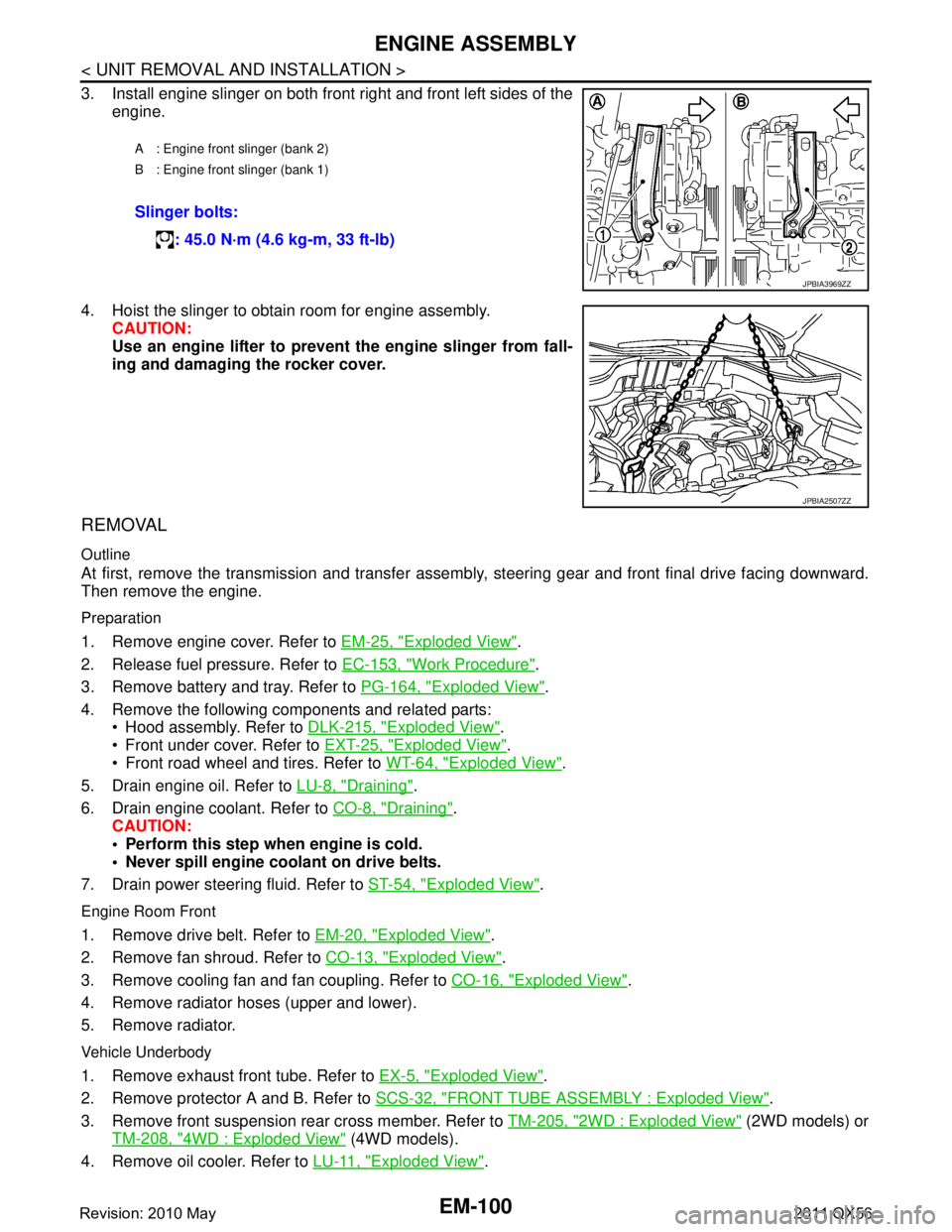
3. Install engine slinger on both front right and front left sides of theengine.
4. Hoist the slinger to obtain room for engine assembly. CAUTION:
Use an engine lifter to prevent the engine slinger from fall-
ing and damaging the rocker cover.
REMOVAL
Outline
At first, remove the transmission and transfer assemb ly, steering gear and front final drive facing downward.
Then remove the engine.
Preparation
1. Remove engine cover. Refer to EM-25, "Exploded View".
2. Release fuel pressure. Refer to EC-153, "
Work Procedure".
3. Remove battery and tray. Refer to PG-164, "
Exploded View".
4. Remove the following components and related parts: Hood assembly. Refer to DLK-215, "
Exploded View".
Front under cover. Refer to EXT-25, "
Exploded View".
Front road wheel and tires. Refer to WT-64, "
Exploded View".
5. Drain engine oil. Refer to LU-8, "
Draining".
6. Drain engine coolant. Refer to CO-8, "
Draining".
CAUTION:
Perform this step when engine is cold.
Never spill engine coolant on drive belts.
7. Drain power steering fluid. Refer to ST-54, "
Exploded View".
Engine Room Front
1. Remove drive belt. Refer to EM-20, "Exploded View".
2. Remove fan shroud. Refer to CO-13, "
Exploded View".
3. Remove cooling fan and fan coupling. Refer to CO-16, "
Exploded View".
4. Remove radiator hoses (upper and lower).
5. Remove radiator.
Vehicle Underbody
1. Remove exhaust front tube. Refer to EX-5, "Exploded View".
2. Remove protector A and B. Refer to SCS-32, "
FRONT TUBE ASSEMBLY : Exploded View".
3. Remove front suspension rear cross member. Refer to TM-205, "
2WD : Exploded View" (2WD models) or
TM-208, "
4WD : Exploded View" (4WD models).
4. Remove oil cooler. Refer to LU-11, "
Exploded View".
A : Engine front slinger (bank 2)
B : Engine front slinger (bank 1)
Slinger bolts:
: 45.0 N·m (4.6 kg-m, 33 ft-lb)
JPBIA3969ZZ
JPBIA2507ZZ
Revision: 2010 May2011 QX56
Page 2711 of 5598
EXL-1
DRIVER CONTROLS
C
DE
F
G H
I
J
K
M
SECTION EXL
A
B
EXL
N
O P
CONTENTS
EXTERIOR LIGHTING SYSTEM
XENON TYPE
PRECAUTION ................ ...............................
5
PRECAUTIONS .............................................. .....5
Precaution for Supplemental Restraint System
(SRS) "AIR BAG" and "SEAT BELT PRE-TEN-
SIONER" ............................................................. ......
5
SYSTEM DESCRIPTION ..............................6
COMPONENT PARTS ................................... .....6
EXTERIOR LIGHTING SYSTEM .................................6
EXTERIOR LIGHTING SYSTEM : Component
Parts Location ..................................................... ......
6
EXTERIOR LIGHTING SYSTEM :
Component Description ............................................
7
FRONT COMBINATION LAMP ............................. ......8
FRONT COMBINATION LAMP : Xenon Head-
lamp ..........................................................................
8
FRONT COMBINATION LAMP : HID control unit ......9
FRONT COMBINATION LAMP : High Beam Sole-
noid ...........................................................................
9
FRONT COMBINATION LAMP : Aiming Motor ........9
FRONT COMBINATION LAMP : Swivel Actuator ......9
SYSTEM .............................................................10
HEADLAMP SYSTEM ...............................................10
HEADLAMP SYSTEM : Syst em Diagram ...............10
HEADLAMP SYSTEM : System Description ....... ....10
HEADLAMP SYSTEM : Fail-safe ............................10
AUTO LIGHT SYSTEM ..... ........................................11
AUTO LIGHT SYSTEM : System Diagram ......... ....11
AUTO LIGHT SYSTEM : System Description (For
CANADA) ................................................................
11
AUTO LIGHT SYSTEM : System Description (Ex-
cept for CANADA) ...................................................
12
DAYTIME RUNNING LIGHT SYSTEM ......................14
DAYTIME RUNNING LIGH T SYSTEM : System
Diagram ............................................................... ....
14
DAYTIME RUNNING LIGHT SYSTEM : System
Description ........................................................... ....
14
ACTIVE ADAPTIVE FRONT-LIGHTING SYSTEM ....14
ACTIVE ADAPTIVE FRONT-LIGHTING SYSTEM
: System Diagram ................................................ ....
15
ACTIVE ADAPTIVE FRONT-LIGHTING SYSTEM
: System Description ................................................
15
ACTIVE ADAPTIVE FRONT-LIGHTING SYSTEM
: Fail-Safe ................................................................
17
HEADLAMP AIMING CONTROL (MANUAL) ...........17
HEADLAMP AIMING CO NTROL (MANUAL) :
System Description .............................................. ....
18
TURN SIGNAL AND HAZARD WARNING LAMP
SYSTEM .....................................................................
18
TURN SIGNAL AND HAZARD WARNING LAMP
SYSTEM : System Diagram ................................ ....
18
TURN SIGNAL AND HAZARD WARNING LAMP
SYSTEM : System Description ................................
18
PARKING, LICENSE PLATE, SIDE MARKER AND
TAIL LAMP SYSTEM ............................................. ....
18
PARKING, LICENSE PLATE, SIDE MARKER
AND TAIL LAMP SYSTEM : System Diagram ........
18
PARKING, LICENSE PLATE, SIDE MARKER
AND TAIL LAMP SYSTEM : System Description ....
19
PARKING, LICENSE PLATE, SIDE MARKER
AND TAIL LAMP SYSTEM : Fail-safe .....................
19
FRONT FOG LAMP SYSTEM ............................... ....19
FRONT FOG LAMP SYSTEM : System Diagram ....20
FRONT FOG LAMP SYSTEM : System Descrip-
tion ....................................................................... ....
20
FRONT FOG LAMP SYSTEM : Fail-Safe ...............20
EXTERIOR LAMP BATTERY SAVER SYSTEM ... ....20
EXTERIOR LAMP BATTERY SAVER SYSTEM :
System Diagram ......................................................
20
Revision: 2010 May2011 QX56
Page 2712 of 5598

EXL-2
EXTERIOR LAMP BATTERY SAVER SYSTEM :
System Description .................................................
21
DIAGNOSIS SYSTEM (BCM) ............................22
COMMON ITEM ..................................................... ...22
COMMON ITEM : CONSULT-III Function (BCM -
COMMON ITEM) ................................................. ...
22
HEADLAMP ........................................................... ...23
HEADLAMP : CONSULT-III Function (BCM -
HEAD LAMP) ..........................................................
23
FLASHER ............................................................... ...25
FLASHER : CONSULT-III Function (BCM -
FLASHER) ..............................................................
25
DIAGNOSIS SYSTEM (IPDM E/R) ....................27
Diagnosis Description .......................................... ...27
CONSULT-III Function (IPDM E/R) ........................29
DIAGNOSIS SYSTEM (AFS) .............................32
CONSULT-III Function (ADAPTIVE LIGHT) ........ ...32
ECU DIAGNOSIS INFORMATION ..............34
BCM, IPDM E/R .............................................. ...34
List of ECU Reference ......................................... ...34
AFS CONTROL UNIT ........................................35
Reference Value .................................................. ...35
Fail-Safe .................................................................38
DTC Inspection Priority Chart .................................39
DTC Index ..............................................................39
WIRING DIAGRAM .....................................40
EXTERIOR LIGHTING SYSTEM .................... ...40
Wiring Diagram .................................................... ...40
BASIC INSPECTION ...................................59
DIAGNOSIS AND REPAIR WORKFLOW ...... ...59
Work Flow ............................................................ ...59
INSPECTION AND ADJUSTMENT ...................61
ADDITIONAL SERVICE WHEN REPLACING
CONTROL UNIT (AFS CONTROL UNIT) .............. ...
61
ADDITIONAL SERVICE WHEN REPLACING
CONTROL UNIT (AFS CONTROL UNIT) : De-
scription ..................................................................
61
ADDITIONAL SERVICE WHEN REPLACING
CONTROL UNIT (AFS CONTROL UNIT) : Special
Repair Requirement ...............................................
61
ADDITIONAL SERVICE WHEN REPLACING
CONTROL UNIT (HEIGHT SENSOR) ................... ...
61
ADDITIONAL SERVICE WHEN REPLACING
CONTROL UNIT (HEIGHT SENSOR) : Descrip-
tion ....................................................................... ...
61
ADDITIONAL SERVICE WHEN REPLACING
CONTROL UNIT (HEIGHT SENSOR) : Special
Repair Requirement ............................................. ...
61
LEVELIZER ADJUSTMENT ......................................61
LEVELIZER ADJUSTMENT : Description ..............61
LEVELIZER ADJUSTMENT : Special Repair Re-
quirement ............................................................. ...
61
DTC/CIRCUIT DIAGNOSIS ........................63
B2503, B2504 SWIVEL ACTUATOR ............. ...63
DTC Logic ............................................................ ...63
Diagnosis Procedure ...............................................64
Component Inspection ............................................67
B2513 HEIGHT SENSOR UNUSUAL [FR] .......68
DTC Logic ............................................................ ...68
Diagnosis Procedure ...............................................68
B2514 HEIGHT SENSOR UNUSUAL [RR] .......71
DTC Logic ............................................................ ...71
Diagnosis Procedure ...............................................71
B2516 SHIFT SIGNAL [P, R] ............................74
DTC Logic ............................................................ ...74
Diagnosis Procedure ...............................................74
B2517 VEHICLE SPEED SIGNAL ....................75
DTC Logic ............................................................ ...75
Diagnosis Procedure ...............................................75
B2519 LEVELIZER CALIBRATION ..................76
DTC Logic ............................................................ ...76
Diagnosis Procedure ...............................................76
B2521 ECU CIRCUIT ........................................77
DTC Logic ............................................................ ...77
Diagnosis Procedure ...............................................77
C0126 STEERING ANGLE SENSOR SIGNAL ...80
DTC Logic ............................................................ ...80
Diagnosis Procedure ...............................................80
C0428 STEERING ANGLE SENSOR CALI-
BRATION ...........................................................
81
DTC Logic ............................................................ ...81
Diagnosis Procedure ...............................................81
U1000 CAN COMM CIRCUIT ............................82
Description ........................................................... ...82
DTC Logic ...............................................................82
Diagnosis Procedure ...............................................82
U1010 CONTROL UNIT (CAN) .........................83
DTC Logic ............................................................ ...83
Diagnosis Procedure ...............................................83
POWER SUPPLY AND GROUND CIRCUIT .....84
AFS CONTROL UNIT ............................................. ...84
AFS CONTROL UNIT : Diagnosis Procedure .........84
Revision: 2010 May2011 QX56
Page 2715 of 5598
![INFINITI QX56 2011 Factory Service Manual
PRECAUTIONSEXL-5
< PRECAUTION > [XENON TYPE]
C
D
E
F
G H
I
J
K
M A
B
EXL
N
O P
PRECAUTION
PRECAUTIONS
Precaution for Supplemental Restraint System (SRS) "AIR BAG" and "SEAT BELT
PRE-TENSIONER"
INFO INFINITI QX56 2011 Factory Service Manual
PRECAUTIONSEXL-5
< PRECAUTION > [XENON TYPE]
C
D
E
F
G H
I
J
K
M A
B
EXL
N
O P
PRECAUTION
PRECAUTIONS
Precaution for Supplemental Restraint System (SRS) "AIR BAG" and "SEAT BELT
PRE-TENSIONER"
INFO](/manual-img/42/57033/w960_57033-2714.png)
PRECAUTIONSEXL-5
< PRECAUTION > [XENON TYPE]
C
D
E
F
G H
I
J
K
M A
B
EXL
N
O P
PRECAUTION
PRECAUTIONS
Precaution for Supplemental Restraint System (SRS) "AIR BAG" and "SEAT BELT
PRE-TENSIONER"
INFOID:0000000006450052
The Supplemental Restraint System such as “A IR BAG” and “SEAT BELT PRE-TENSIONER”, used along
with a front seat belt, helps to reduce the risk or severi ty of injury to the driver and front passenger for certain
types of collision. This system includes seat belt switch inputs and dual stage front air bag modules. The SRS
system uses the seat belt switches to determine the front air bag deployment, and may only deploy one front
air bag, depending on the severity of a collision and whether the front occupants are belted or unbelted.
Information necessary to service the system safely is included in the “SRS AIR BAG” and “SEAT BELT” of this
Service Manual.
WARNING:
• To avoid rendering the SRS inoper ative, which could increase the risk of personal injury or death in
the event of a collision that would result in air ba g inflation, all maintenance must be performed by
an authorized NISSAN/INFINITI dealer.
Improper maintenance, including in correct removal and installation of the SRS, can lead to personal
injury caused by unintentional act ivation of the system. For removal of Spiral Cable and Air Bag
Module, see the “SRS AIR BAG”.
Do not use electrical test equipm ent on any circuit related to the SRS unless instructed to in this
Service Manual. SRS wiring harnesses can be identi fied by yellow and/or orange harnesses or har-
ness connectors.
PRECAUTIONS WHEN USING POWER TOOLS (AIR OR ELECTRIC) AND HAMMERS
WARNING:
When working near the Air Bag Diagnosis Sensor Unit or other Air Bag System sensors with the
ignition ON or engine running, DO NOT use air or electric power tools or strike near the sensor(s)
with a hammer. Heavy vibration could activate the sensor(s) and deploy the air bag(s), possibly
causing serious injury.
When using air or electric power tools or hammers , always switch the ignition OFF, disconnect the
battery, and wait at least 3 minutes before performing any service.
Revision: 2010 May2011 QX56
Page 2718 of 5598
![INFINITI QX56 2011 Factory Service Manual
EXL-8
< SYSTEM DESCRIPTION >[XENON TYPE]
COMPONENT PARTS
*1: With AFS system models
*
2: With headlamp aiming control system (manual) models
FRONT COMBINATION LAMP
FRONT COMBINATION LAMP : Xenon Head INFINITI QX56 2011 Factory Service Manual
EXL-8
< SYSTEM DESCRIPTION >[XENON TYPE]
COMPONENT PARTS
*1: With AFS system models
*
2: With headlamp aiming control system (manual) models
FRONT COMBINATION LAMP
FRONT COMBINATION LAMP : Xenon Head](/manual-img/42/57033/w960_57033-2717.png)
EXL-8
< SYSTEM DESCRIPTION >[XENON TYPE]
COMPONENT PARTS
*1: With AFS system models
*
2: With headlamp aiming control system (manual) models
FRONT COMBINATION LAMP
FRONT COMBINATION LAMP : Xenon HeadlampINFOID:0000000006213889
OUTLINE
The lamp light source is by the arch discharge by
applying high voltage into the xenon gas-filled bulb instead
of the halogen bulb filament.
Sight becomes more natural and brighter because the amount of light are gained adequately and the color of
light is sunshine-like white.
The xenon bulb drops the amount of light, repeats blinking, and illuminates in red if the bulb reaches the ser-
vice life.
ILLUMINATION PRINCIPLE
1. Discharging starts in high voltage pulse between bulb elec- trodes.
2. Xenon gas is activated by curr ent between electrodes. Pale light
is emitted.
3. The luminous tube (bulb) temperature elevates. Evaporated halide is activated by discharge. The color of light changes into
white.
NOTE:
Brightness and the color of light may change slightly immediately after the headlamp turned ON until the xenon bulb becomes sta-
ble. This is not malfunction.
Illumination time lag may occur between right and left. This is not
malfunction.
PRECAUTIONS FOR TROUBLE DIAGNOSIS
Representative malfunction examples are; "Light does not turn ON", "Light blinks", and "Brightness is inade-
quate." The cause often be the xenon bulb. Such malf unctions, however, are occurred occasionally by HID
control unit malfunction or lamp case malfunction. S pecify the malfunctioning part with diagnosis procedure.
WARNING:
Never touch the harness, HID control unit, the inside and metal part of lamp when turning the head-
lamp ON or operating the lighting switch.
Never work with wet hands.
CAUTION:
Never perform HID control unit circuit diagnosis with a circuit tester or an equivalent.
Temporarily install the headlamps on the vehicle. Co nnect the battery to the connector (vehicle side)
when checking ON/OFF status.
Disconnect the battery negative terminal before di sconnecting the lamp socket connector or the har-
ness connector.
Check for fusing of the fusible link(s), open around connector, short, disconnection if the symptom
is caused by electric error.
NOTE:
Turn the switch OFF once before turni ng ON, if the ON/OFF is inoperative.
The xenon bulb drops the amount of light, repeats blinking, and illuminates in red if the bulb reaches the ser-
vice life.
Steering angle sensor*1Transmits steering angle sensor signal to AFS control unit. (via CAN communication)
Combination switch
(Lighting & turn signal switch) Refer to
BCS-7, "
COMBINATION SWITCH READING SYSTEM : System Descrip-
tion".
Door switch Inputs the door switch signal to BCM.
AFS switch*
1 Inputs the AFS switch signal to AFS control unit.
AFS switch is integrated in triple switch.
Headlamp aiming switch*
2Outputs the aiming motor drive signal to aiming motor.
Hazard switch Inputs the hazard switch signal to BCM. Part Description
JPLIA0421GB
Revision: 2010 May2011 QX56